Embedded Programming
Week 9 - Embedded Programming
Here you will find my work description during this nineth week
General info
Class notes
Assignment
Our assignment for this week is:
Group Assignement
- experiment with other architectures
Individual Assignement
- Read a microcontroller data sheet.
- Program your board to do something, with as many different programming languages and programming environments as possible.
- Optionally, experiment with other architectures
Usefull links
ATtiny84
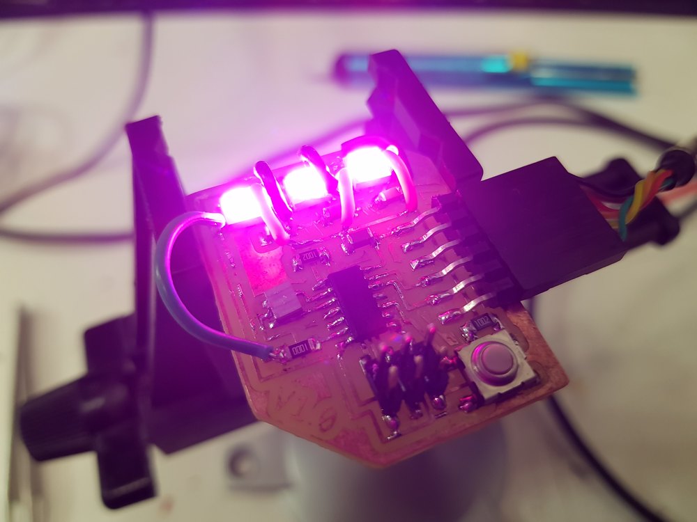
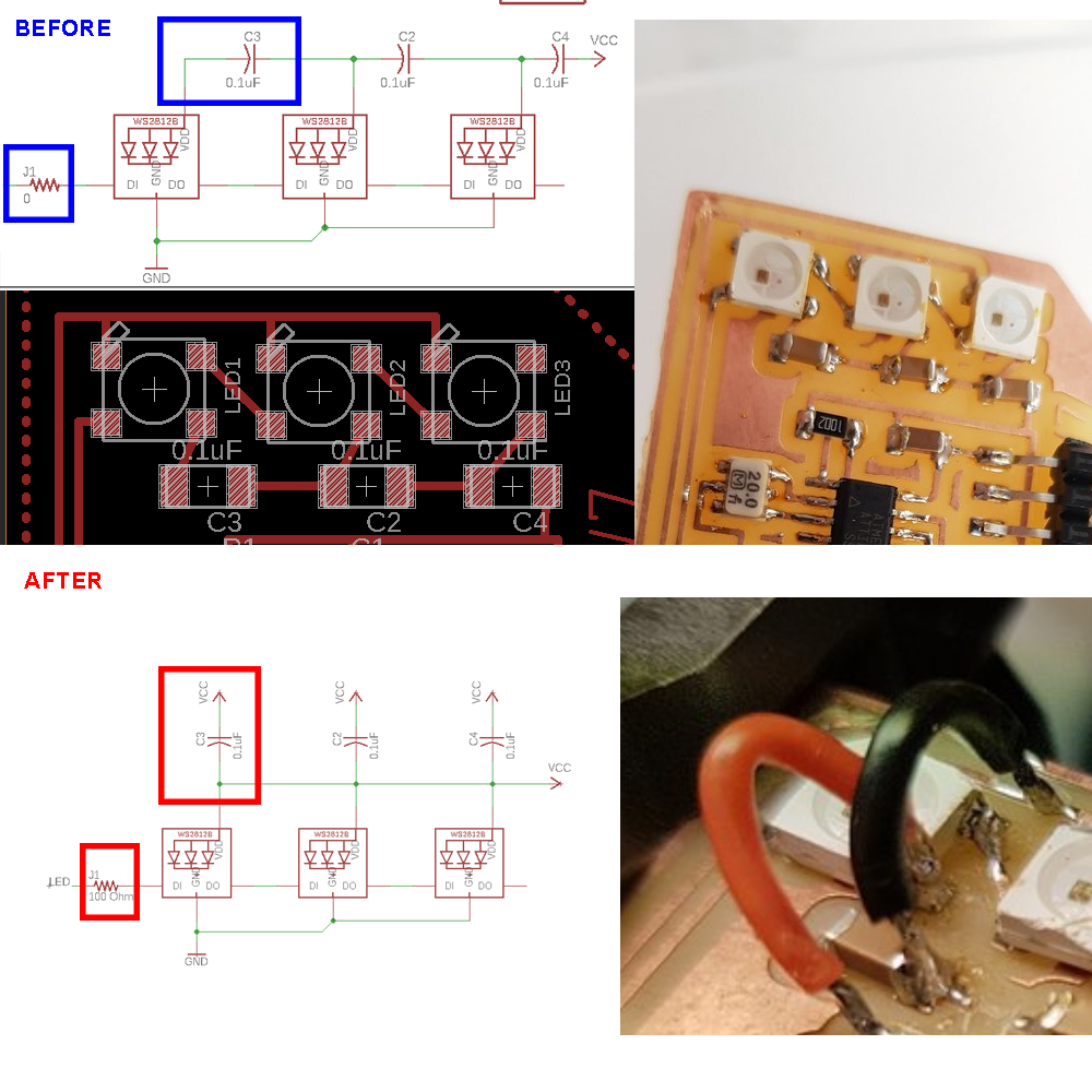
The board made in Week 6 was not programmed. It was functionnal as I used avrdude with fabISP to burn the bootloader, but I tried lighting up the LED but without success. So I decided go dive into what was wrong. It was ambitious to put WS2812b without knowing how they work, but that is why we are experiencing. I firgured out thant the design I did was not correct. I misunderstood how neopixels work, probably because I didn’t know how to read the schematics. By luck I knew where to put my attention, I had to frankenhack the board to find the problems. It shows the importance of reading datasheets.
Datasheet
Reading the ATtiny datasheet I realised error I made, like using wrong Pin numbers.

ATtiny84 specifications
- Small: 14 pins
- Cheap: ~0.5€
- Same family as most Arduino chips, AVR manufactured by Microchip formerly Atmel.
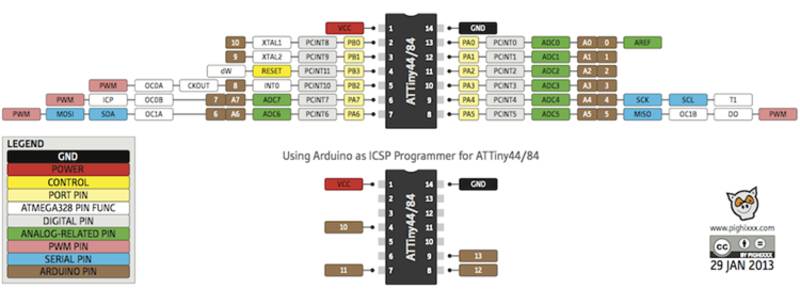
ATtiny 24/44/84 pinouts
Things I learnt reading datasheets:
MCU architecture
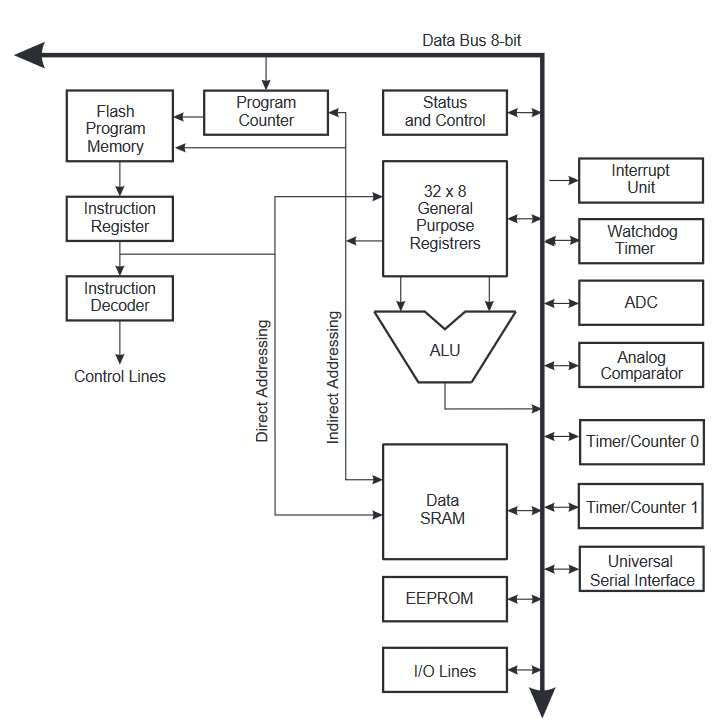
- fuses are configuration bits. MCU use them to change its behaviour (external or internal clock, frequency of the clock)
- Input/ Ouputs pins configuration
- the memory is very important : it’s a big array of switches
- 32x 8bits Registers : the first row (registers) change the state of the pins, a row hav 8 switches (0 yo 7), a row have an address
- PORTA, DDRA, PINA are used to control our pins
- PA7 is pin 6 on chip
DDRx register is used to tell if pin is an input or an output (data direction register) PORTx (port x data register) read data from pin PINx (port x input register) write data
- interruptions, could be internal of external, used for asynchonism
- To understand what you can do with the MCU, read the features paragraph.
- There is an inner A/D (Analog to Digital)
- it use a 10 bits resolution (analog values from 0 to 1023)
- PWM (pulse with modulation) use 8bits resotlution (values from 0 to 254)
- MCU has a native SPI interface (used to program it using MISO and MOSI pins)
Investigating
Using sample code from adafruit to try to turn on one WS2812b. External resonator not used because the WS2812b protocol have to use a 8Mhz or 16Mhz signals, so I burned a new bootloader using internal 8Mhz clock.
.jpg)
.jpg)
Once I achieved those changes, I tried different software configurations to find how to turn on one LED.
I find out that I have to use NEO_KHZ400 instead of NEO_KHZ800.
Wrong PIN addressing. After reading the datasheet I realise that LED ar connected to pin 6 (of the chip) but called it is PIN 7 for arduino !
Using Arduino IDE
Using Adafruit button cycler exemple as a starting point
Adding switch mode feature from serial communication
I started with the DigitalSerialRead from provided template.
#include <SoftwareSerial.h>
const int rx=12;
const int tx=13;
SoftwareSerial mySerial(rx,tx);

// digital pin 2 has a pushbutton attached to it. Give it a name:
int pushButton = 10;

// the setup routine runs once when you press reset:
void setup() {
  // initialize serial communication at 9600 bits per second:
  mySerial.begin(9600);
  // make the pushbutton's pin an input:
  pinMode(pushButton, INPUT);
}

// the loop routine runs over and over again forever:
void loop() {
  // read the input pin:
  int buttonState = digitalRead(pushButton);
  // print out the state of the button:
  mySerial.println(buttonState);
  delay(1);        // delay in between reads for stability
}
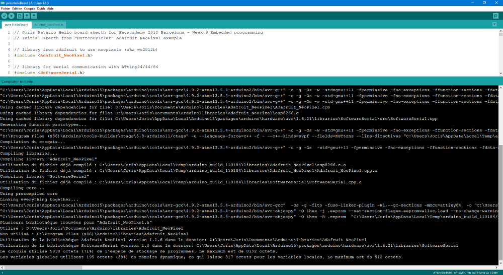
Here you can the result:
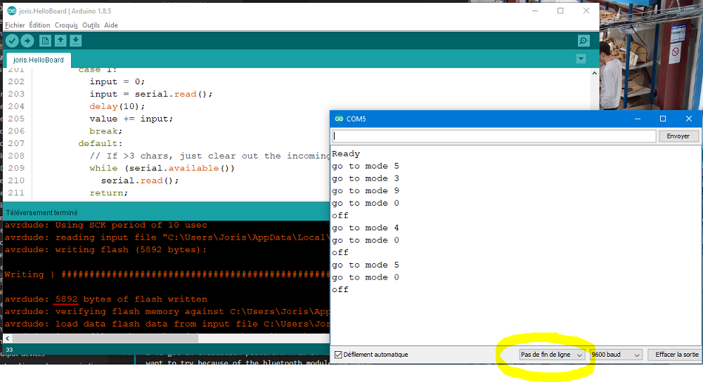
.jpg)
You can see memory used is 6k, that’s why I decided to use from the begenning a ATtiny84 instead of an ATtiny44 (that has only 4k of memory).
Files to download
Click here to download Arduino IDE code
Using GNU AVR Toolchain
Arduino IDE under ARM64 Linux (Pine64)
I would like to set up a new environment using a Pine64 laptop I own (That computer use a Pine64 board, like Raspberry Pi) and run on Xenial Mate. So I took time to setup Git, Arduino, Jekyll … to run a new developpement environment in order to use it to develop a C version of the board.
Unfortunately, the arduino version you can install on official packages repository is an old version (1.0.6 in think) and there is no meny to add ATtiny extra board (no Board manager). I tried install the board manually but I ran out of time using the preference.txt file.
So I did not manage to code using arduino for ATTiny in this environment.

AVR GCC toolchain : avr-gcc + avr-ar + avr -objcopy + avrdude
Let’s try using AVR tool chain
start with a blasic project
#include <avr/io.h>
#include <util/delay.h>
#include <avr/pgmspace.h>

void setup() {

}


void loop() {

}

int main(void) {

    setup();

    while(1){
        loop();
    }
}
write makefile
PROJECT=hello.joris.84
SOURCES=$(PROJECT).c
MMCU=attiny84
F_CPU = 8000000

CFLAGS=-mmcu=$(MMCU) -Wall -Os -DF_CPU=$(F_CPU)

$(PROJECT).hex: $(PROJECT).out
	avr-objcopy -O ihex $(PROJECT).out $(PROJECT).c.hex;\
	avr-size --mcu=$(MMCU) --format=avr $(PROJECT).out

$(PROJECT).out: $(SOURCES)
	avr-gcc $(CFLAGS) -I./ -o $(PROJECT).out $(SOURCES)

program-usbtiny: $(PROJECT).hex
	avrdude -p t84 -Cavrdude.conf -P usb -c usbtiny -U flash:w:$(PROJECT).c.hex
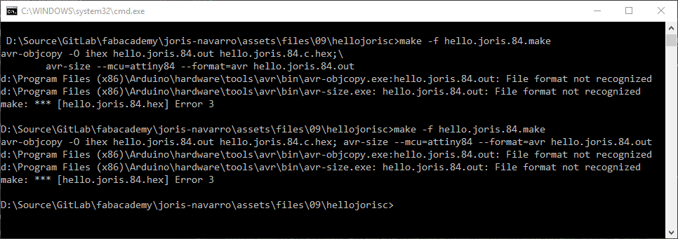
Run make to compile
make -f hello.joris.84.make
and upload using avr tools (using fabisp)
make -f hello.joris.84.make program-usbtiny
But it does not work because of arduino version !

(git add, commit, push) Back to windows (git pull), and try again.
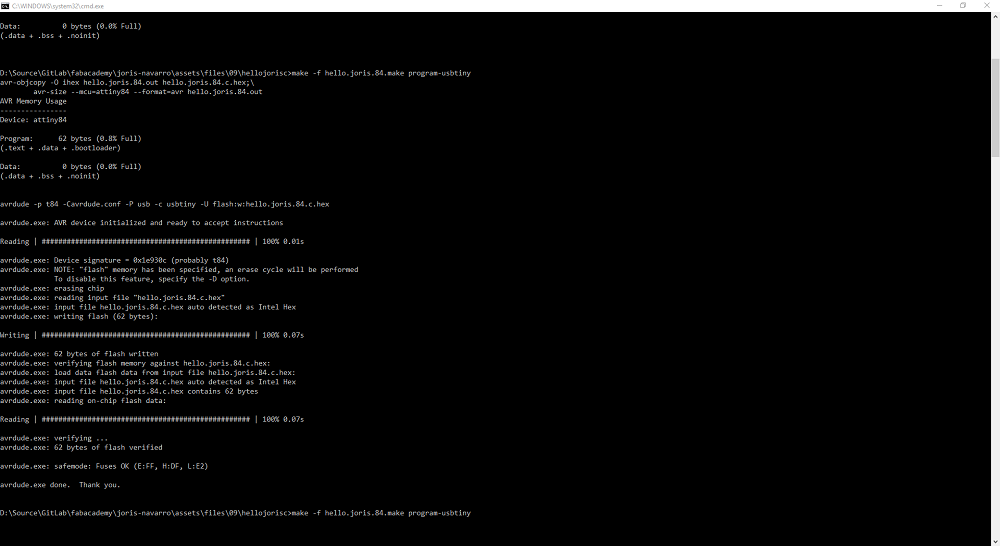
And it works !
now update c file with the code I wrote for arduino (basically copy paste). I used notepad++ as text editor.
Remember to add arduino.h
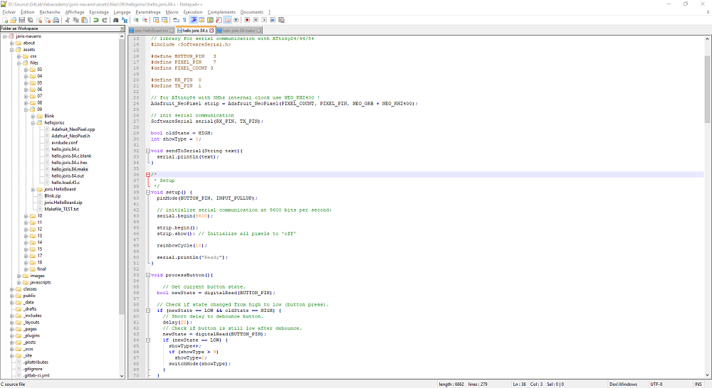
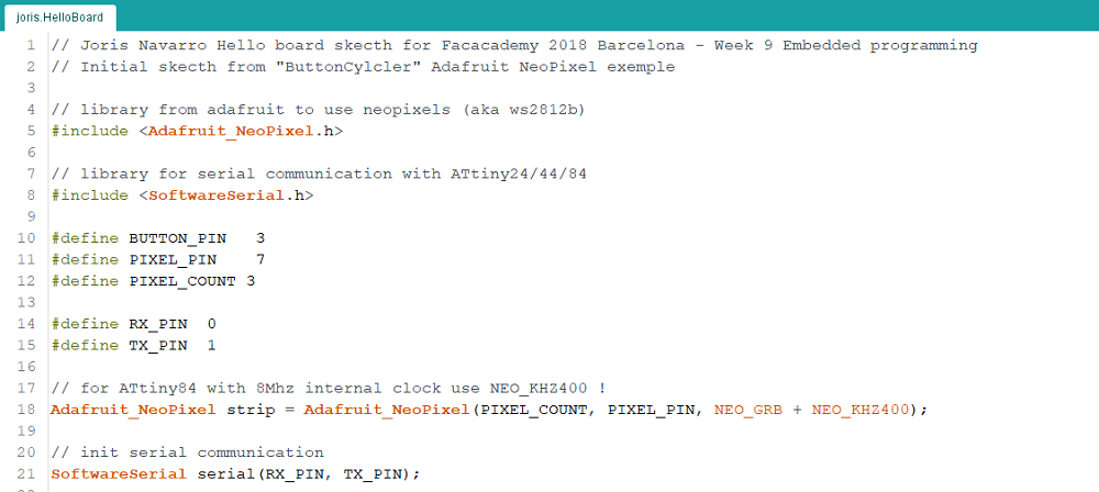
Here is the full C code
// Joris Navarro Hello board skecth for Facacademy 2018 Barcelona - Week 9 Embedded programming
//
// hello.joris.84.c
//
#include <avr/io.h>
#include <util/delay.h>
#include <avr/pgmspace.h>
#include <Arduino.h>
// library from adafruit to use neopixels (aka ws2812b)
#include <Adafruit_NeoPixel.h>
// library for serial communication with ATtiny24/44/84
#include <SoftwareSerial.h>
#define BUTTON_PIN 3
#define PIXEL_PIN 7
#define PIXEL_COUNT 3
#define RX_PIN 0
#define TX_PIN 1
// for ATtiny84 with 8Mhz internal clock use NEO_KHZ400 !
Adafruit_NeoPixel strip = Adafruit_NeoPixel(PIXEL_COUNT, PIXEL_PIN, NEO_GRB + NEO_KHZ400);
// init serial communication
SoftwareSerial serial(RX_PIN, TX_PIN);
bool oldState = HIGH;
int showType = 0;
void sendToSerial(String text){
serial.println(text);
}
/*
* Setup
*/
void setup() {
pinMode(BUTTON_PIN, INPUT_PULLUP);
// initialize serial communication at 9600 bits per second:
serial.begin(9600);
strip.begin();
strip.show(); // Initialize all pixels to 'off'
rainbowCycle(10);
serial.println("Ready");
}
void processButton(){
// Get current button state.
bool newState = digitalRead(BUTTON_PIN);
// Check if state changed from high to low (button press).
if (newState == LOW && oldState == HIGH) {
// Short delay to debounce button.
delay(20);
// Check if button is still low after debounce.
newState = digitalRead(BUTTON_PIN);
if (newState == LOW) {
showType++;
if (showType > 9)
showType=0;
switchMode(showType);
}
}
// Set the last button state to the old state.
oldState = newState;
}
// Fill the dots one after the other with a color
void colorWipe(uint32_t c, uint8_t wait) {
for(uint16_t i=0; i<strip.numPixels(); i++) {
strip.setPixelColor(i, c);
strip.show();
delay(wait);
}
}
void rainbow(uint8_t wait) {
uint16_t i, j;
for(j=0; j<256; j++) {
for(i=0; i<strip.numPixels(); i++) {
strip.setPixelColor(i, Wheel((i+j) & 255));
}
strip.show();
delay(wait);
}
}
// Slightly different, this makes the rainbow equally distributed throughout
void rainbowCycle(uint8_t wait) {
uint16_t i, j;
for(j=0; j<256*5; j++) { // 5 cycles of all colors on wheel
for(i=0; i< strip.numPixels(); i++) {
strip.setPixelColor(i, Wheel(((i * 256 / strip.numPixels()) + j) & 255));
}
strip.show();
delay(wait);
}
}
//Theatre-style crawling lights.
void theaterChase(uint32_t c, uint8_t wait) {
for (int j=0; j<10; j++) { //do 10 cycles of chasing
for (int q=0; q < 3; q++) {
for (int i=0; i < strip.numPixels(); i=i+3) {
strip.setPixelColor(i+q, c); //turn every third pixel on
}
strip.show();
delay(wait);
for (int i=0; i < strip.numPixels(); i=i+3) {
strip.setPixelColor(i+q, 0); //turn every third pixel off
}
}
}
}
//Theatre-style crawling lights with rainbow effect
void theaterChaseRainbow(uint8_t wait) {
int modulo = 2; // used to be 3
for (int j=0; j < 256; j++) { // cycle all 256 colors in the wheel
for (int q=0; q < 3; q++) {
for (int i=0; i < strip.numPixels(); i=i+modulo) {
strip.setPixelColor(i+q, Wheel( (i+j) % 255)); //turn every modulo pixel on
}
strip.show();
delay(wait);
for (int i=0; i < strip.numPixels(); i=i+modulo) {
strip.setPixelColor(i+q, 0); //turn every modulo pixel off
}
}
}
}
// Input a value 0 to 255 to get a color value.
// The colours are a transition r - g - b - back to r.
uint32_t Wheel(byte WheelPos) {
WheelPos = 255 - WheelPos;
if(WheelPos < 85) {
return strip.Color(255 - WheelPos * 3, 0, WheelPos * 3);
}
if(WheelPos < 170) {
WheelPos -= 85;
return strip.Color(0, WheelPos * 3, 255 - WheelPos * 3);
}
WheelPos -= 170;
return strip.Color(WheelPos * 3, 255 - WheelPos * 3, 0);
}
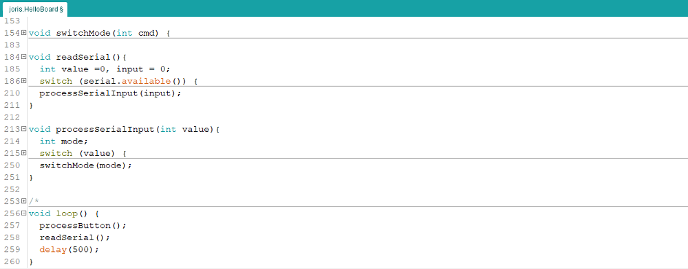
void switchMode(int cmd) {
serial.print("go to mode ");
serial.println(cmd);
switch(cmd){
case 0: colorWipe(strip.Color(0, 0, 0), 50); // Black/off
sendToSerial("off");
break;
case 1: colorWipe(strip.Color(255, 0, 0), 50); // Red
break;
case 2: colorWipe(strip.Color(0, 255, 0), 50); // Green
break;
case 3: colorWipe(strip.Color(0, 0, 255), 50); // Blue
break;
case 4: theaterChase(strip.Color(127, 127, 127), 50); // White
break;
case 5: theaterChase(strip.Color(127, 0, 0), 50); // Red
break;
case 6: theaterChase(strip.Color( 0, 0, 127), 50); // Blue
break;
case 7: rainbow(20);
break;
case 8: rainbowCycle(20);
break;
case 9: theaterChaseRainbow(50);
break;
default:
return;
}
}
void readSerial(){
int value =0, input = 0;
switch (serial.available()) {
/* Serial.available() is the number of bytes waiting. Convert from
* ASCII val to an int. Intentional switch-case fall through below.
*/
case 3:
value = serial.read();
value -= 48;
value *= 10;
case 2:
value += serial.read();
value -= 48;
value *= 10;
case 1:
input = 0;
input = serial.read();
delay(10);
value += input;
break;
default:
// If >3 chars, just clear out the incoming buffer.
while (serial.available())
serial.read();
return;
}
processSerialInput(input);
}
void processSerialInput(int value){
int mode;
switch (value) {
case 'a':
mode = 0;
break;
case 'b':
mode = 1;
break;
case 'c':
mode = 2;
break;
case 'd':
mode = 3;
break;
case 'e':
mode = 4;
break;
case 'f':
mode = 5;
break;
case 'g':
mode = 6;
break;
case 'h':
mode = 7;
break;
case 'i':
mode = 8;
break;
case 'j':
mode = 9;
break;
default:
mode = 0;
break;
}
switchMode(mode);
}
/*
* Loop
*/
void loop() {
processButton();
readSerial();
delay(500);
}
int main(void) {
setup();
while(1){
loop();
}
}
does not compile; looks like we have a path issue
run avr-gcc -print-file-name=include

trying to find the pathes used to includ by the linker and the compiler
issue with provided Arduino version that used an obsolete WProgram.h => Add ARDUINO=10805
Arduino IDE uses a tool called Arduino-builder
Another tool that can be usefull is Arduino-Makefile
Not finished : apparently, Arduino IDE convert code into c++ and compile it using avr-g++, where the makefile I use (from neil) is for C. So I should miss a step.
i read a lot of stuff about this, and this is not a simple task.
May be I will finish it later … to be continued.
Files to download
Stay in touch
Hi, I'm
Joris Navarro, from Perpignan (France), a proud dad, a fab director/manager, a teacher, a ceo, a FabAcademy student, but not only. Click here to know more about me.
Check my work for FabAcademy on FabCloud GitLab
@joris.navarro.
Want to say Hi ? Please send me a message.