Output devices
Week 12 - Output devices
Here you will find my work description during this twelfth week
General info
Class notes
Assignments
- individual assignment: add an output device to a microcontroller board you’ve designed, and program it to do something
- group assignment: measure the power consumption of an output device
Group assignement
Bi polar stepper motor
I want to design a board that can drive a bipolar stepper motor using end stop swith and ftdi serial to send commands.
Using the Neil bipolar hello board as reference:
Niel provide the Kokopeli design of the board.
I decided to redesign this board to study how h-bridges work. To update the board I will add an ftdi interface. That way I will be able to send command using the serial bus to the motor.
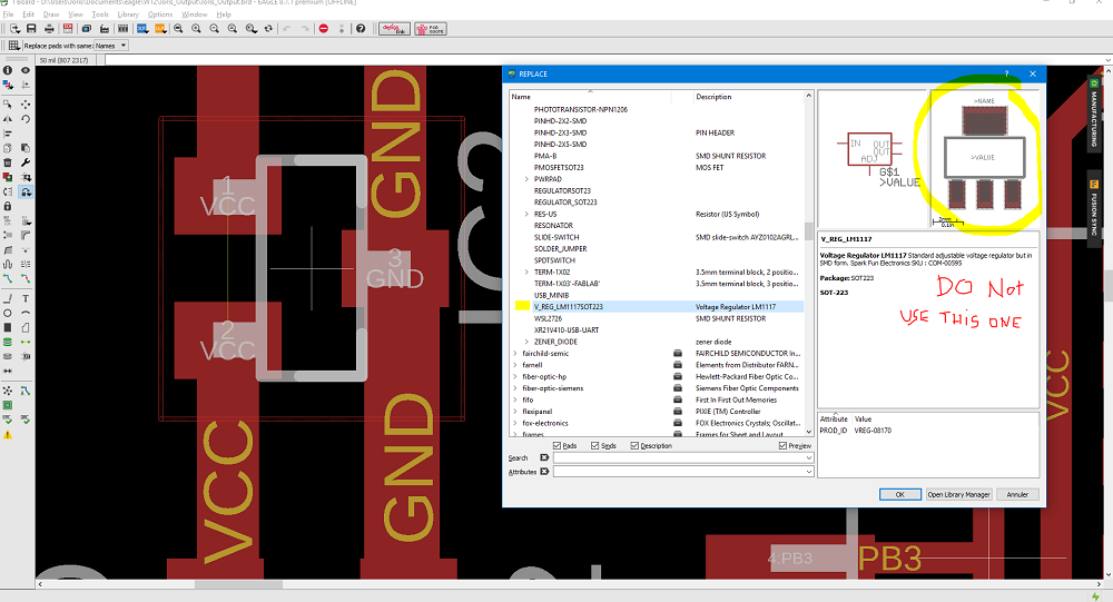
Voltage regulator
Santi warn us about the voltage regulator that is in the stock. Check datasheet because it could be different than the one in the fablab inventory and some former student had issue using it. Datasheet LM3480 100-mA, SOT-23, Quasi Low-Dropout Linear Voltage Regulator
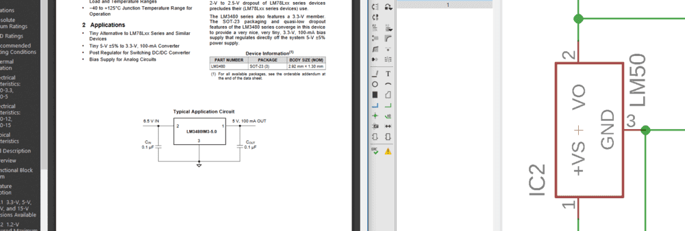
After reading the datasheet I finally find out that the point was the footprint of the component. the one in the fab inventory has a different footprint.
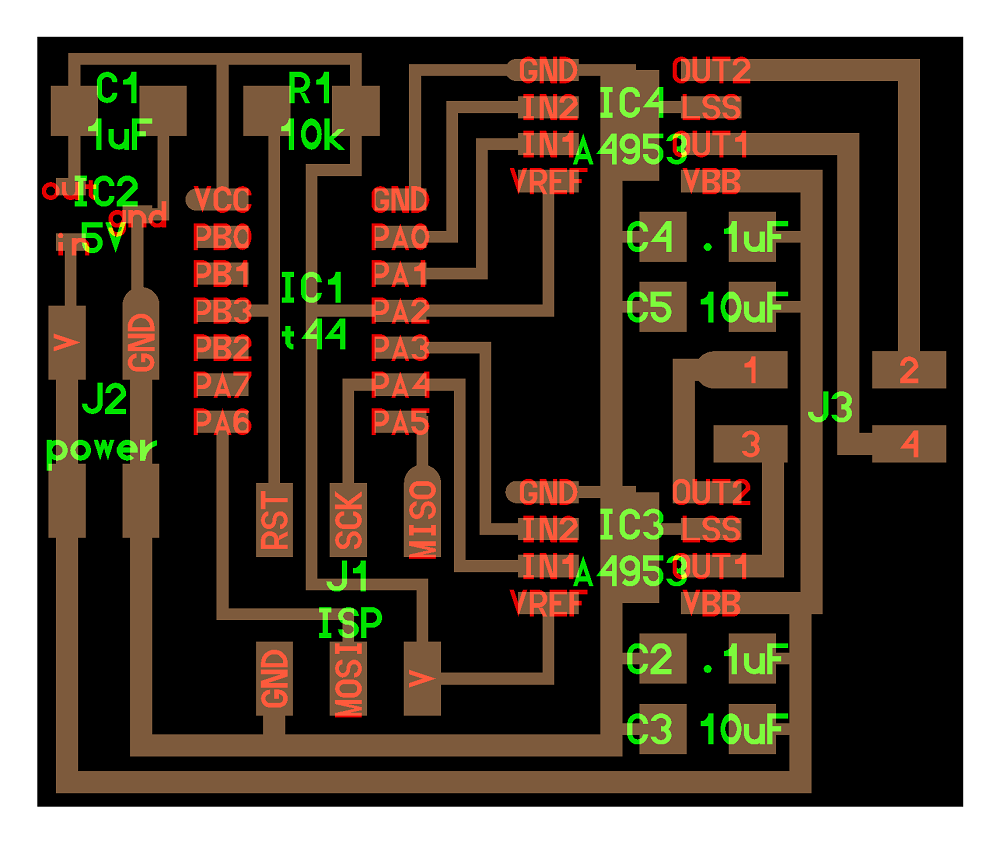
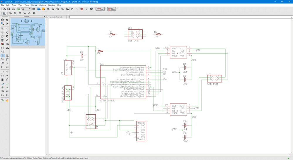
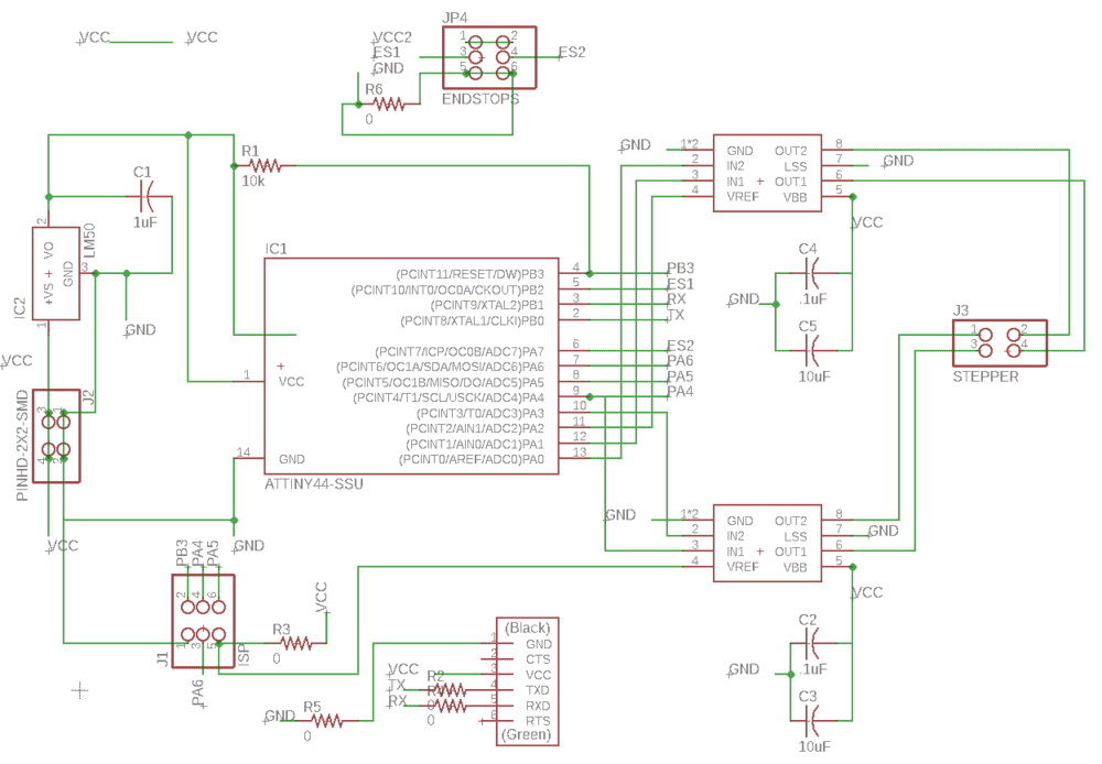
Eagle
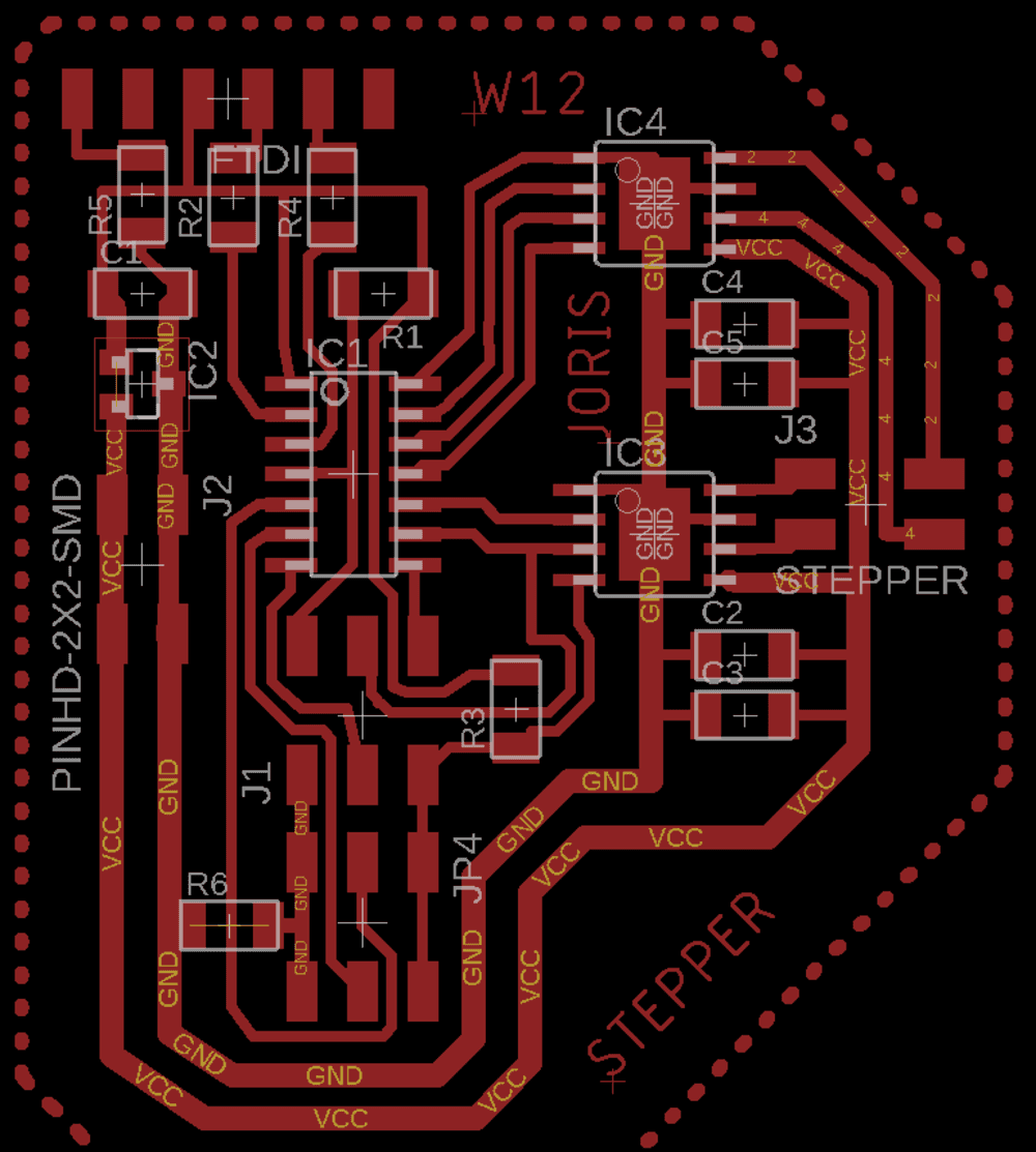
I started desiging the board including the update I wanted.
Routing
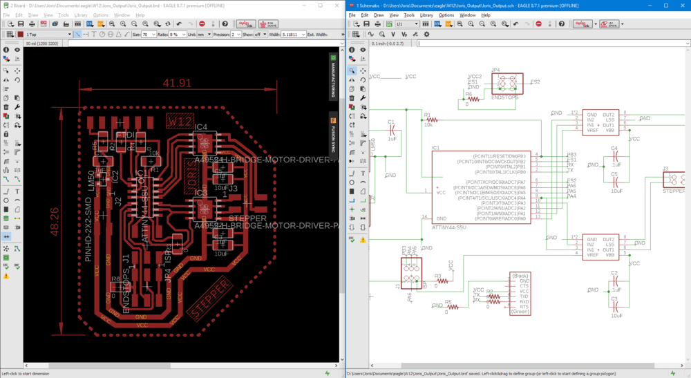
Adding zero resistors as jumper to route the ftdi header.
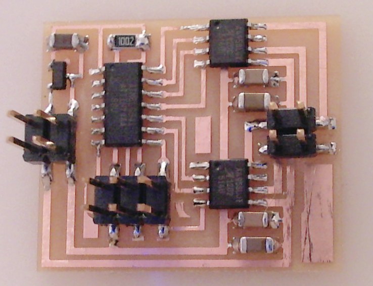
Result board
Stepper
In parallel I wanted to learn more about steppers. I felt like stepper (and generaly motors) is a science.
Bibolars, unipolars, Coils, shafts, torque … everthing you want to know about stepper is explained the the excellent Adafruit stepper guide or you can download the PDF version.
The next step is to read the Datasheet of the motor I am going to use (42SHD0001).
This one comes from china and cost aroud 10$.
The key point informations about this motors are:
- Reference :42SHD0001
- 2 phases
- 200 steps = 1.8°/step
- Torque : 260 mN.m
- Current : 1.5 A
- Voltage : 3.7-12V
-
D shaft
- Dimensions:
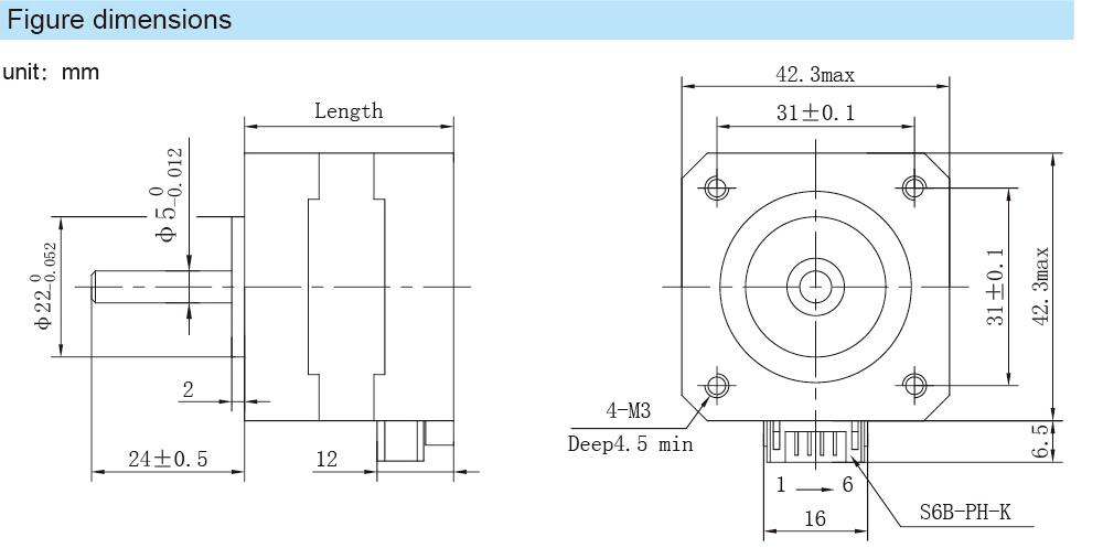
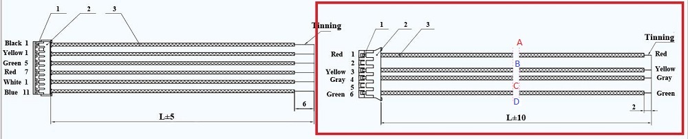
- Coils configuration is important for the wiring
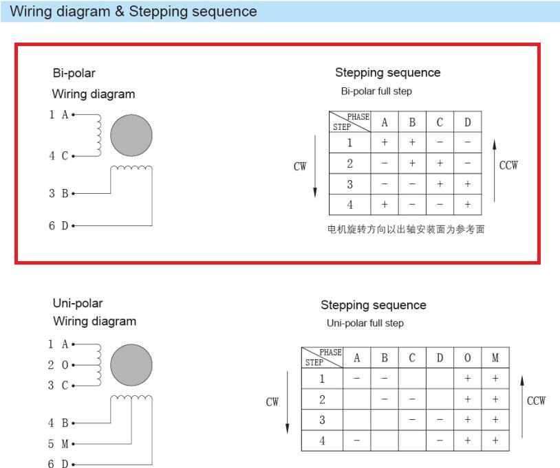
This table is important to know how to send signals to turn the motor clockwise or counterclockwise.
The signals are sent by the MCU to 4 pins A,B,C and D but the moteur can hanve 6 wires. Check the following picture to understand how to use those wires.
To send those signals synchronously we are going to use the PWM (Pulse Width Modulation) but the current is not managed by the MCU for that we are going to use a double H-bridge.
Why double h-bridge ? because we want the motor to go both way CW and CCW, for that we should have to reverse the polarity.
The motor use 3.7 to 12V, and will be powered by a 9V battery but that voltage is not supported by the ATtiny, we used a voltage regulator to set the voltage that goes to the MCU to 5 volts. The Hbridge are conneted to the battery and the MCU, receive PWM from the MCU and manage the voltage that goes to the motor.
A4952 Full-Bridge DMOS PWM Motor Drivers datasheet
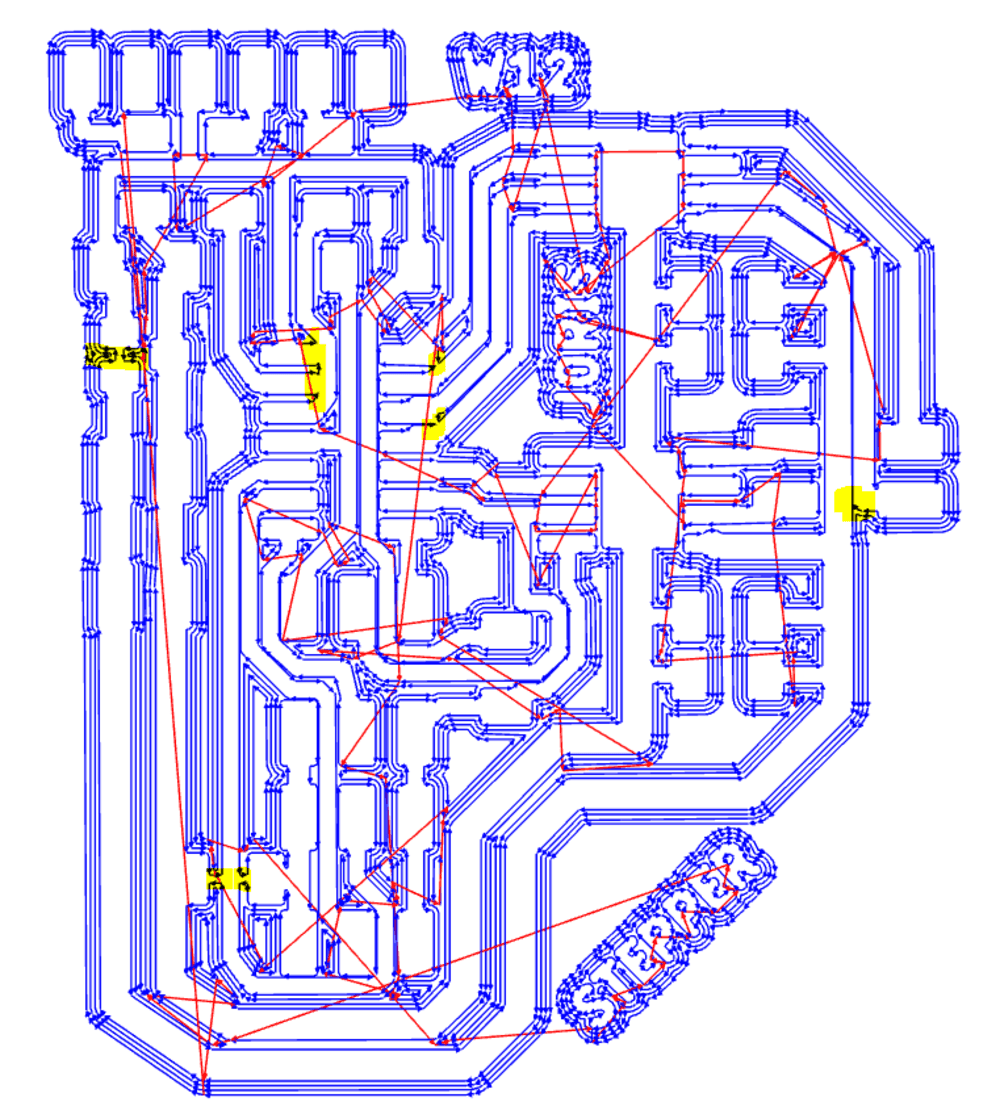
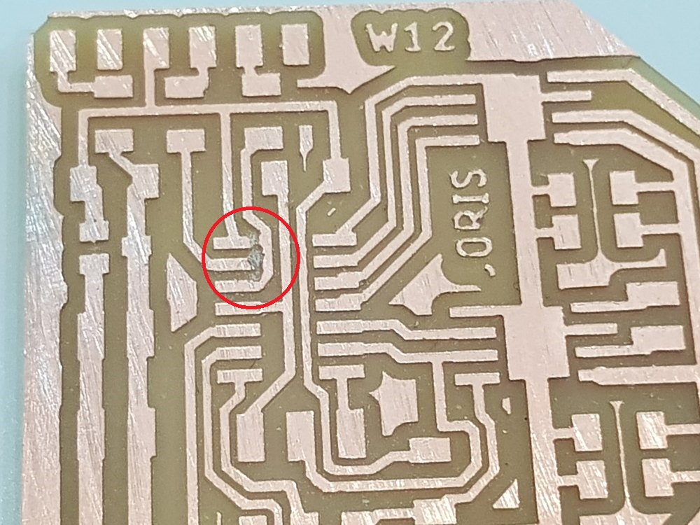
Milling
Mods
Since my first experiment of designing my PCB (I had troubles because of toolpathes) even using the eagle DRC. I was aware of some issues on toolpath.
I checked the generated toolpath from mods and find out some point to keep an eye on.
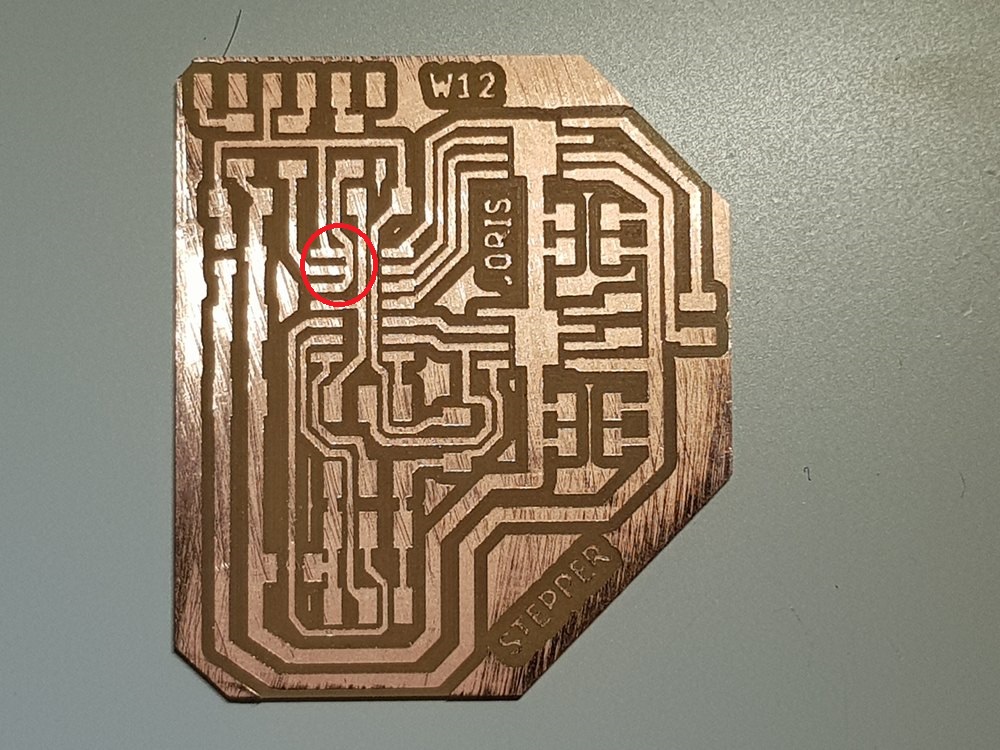
The board
And I was right !
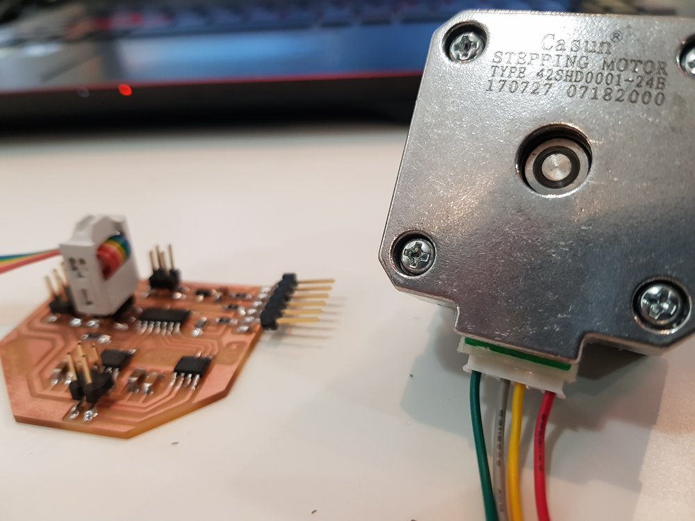
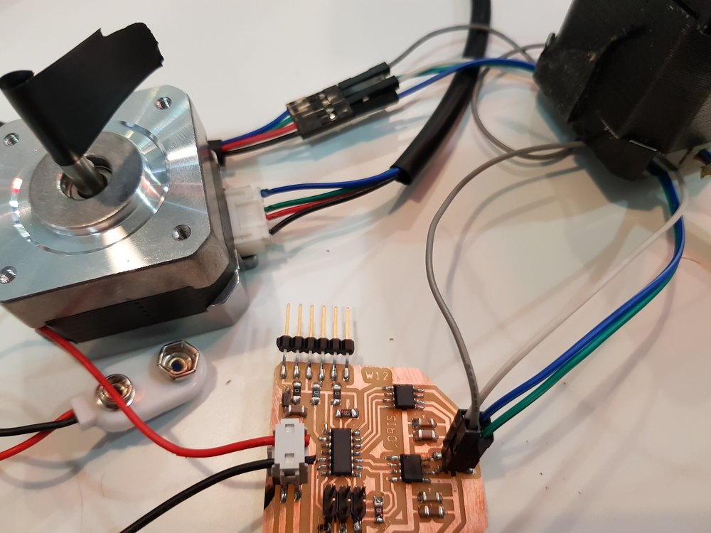
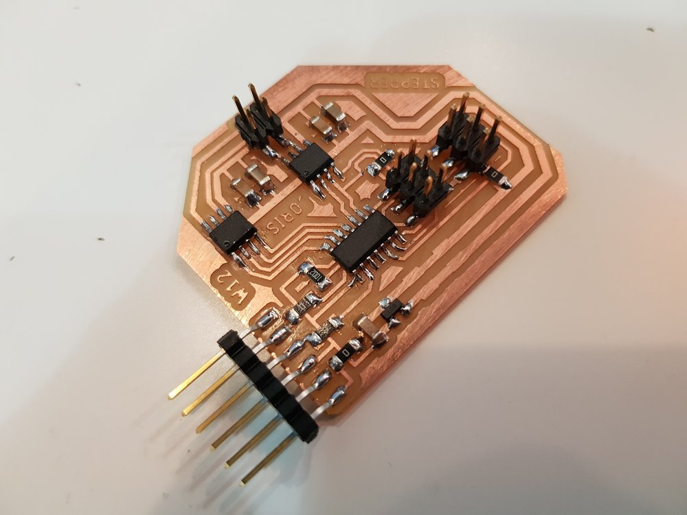
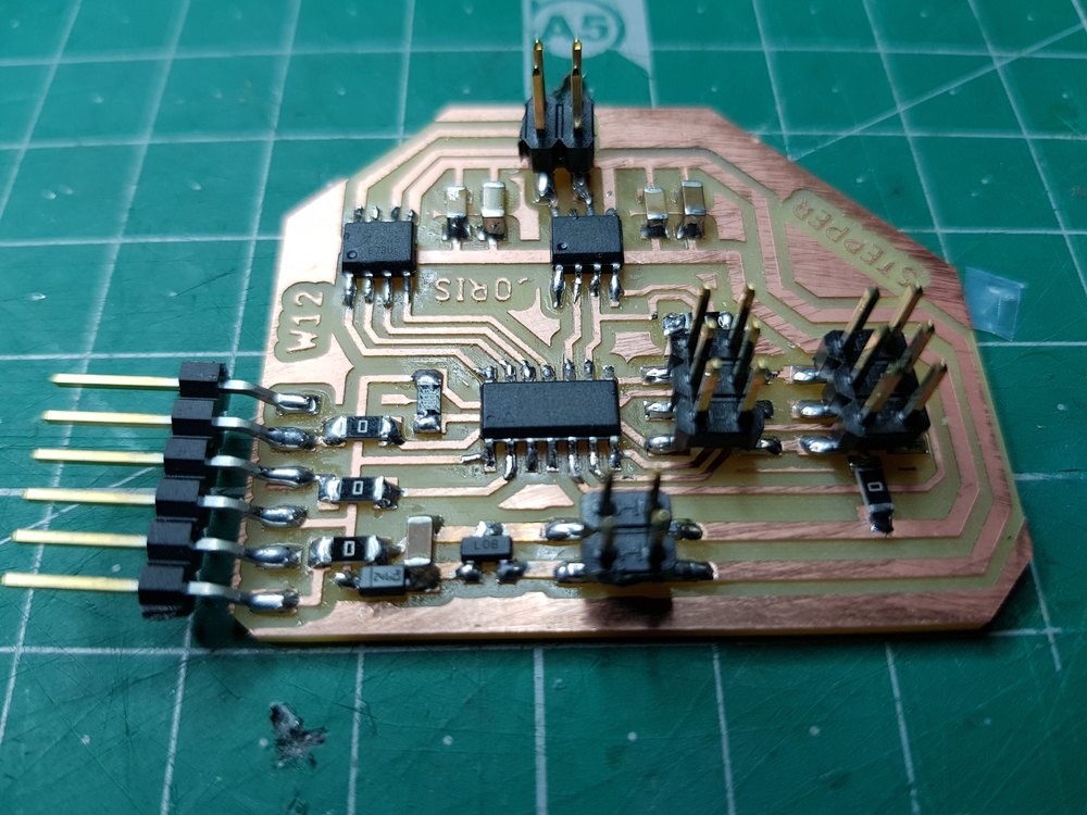
Soldering
I solder the components without difficulties, here is the result.
Issue we had to deal with
Adding a new Ftdi interface add a new concern. The board is powered by an 9v battery. I figured out that plug in the ftdi cable makes the voltage regulator super hot very quicly. This was because 5V comes from the computer USB to the output of the regulator. Actually the board was designed to be powered by the battery and not from 2 sources.
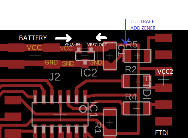
I cut the ftdi vcc trace before the regulator and add a zener diode that prevent the current in one way (the cathode side has a line).
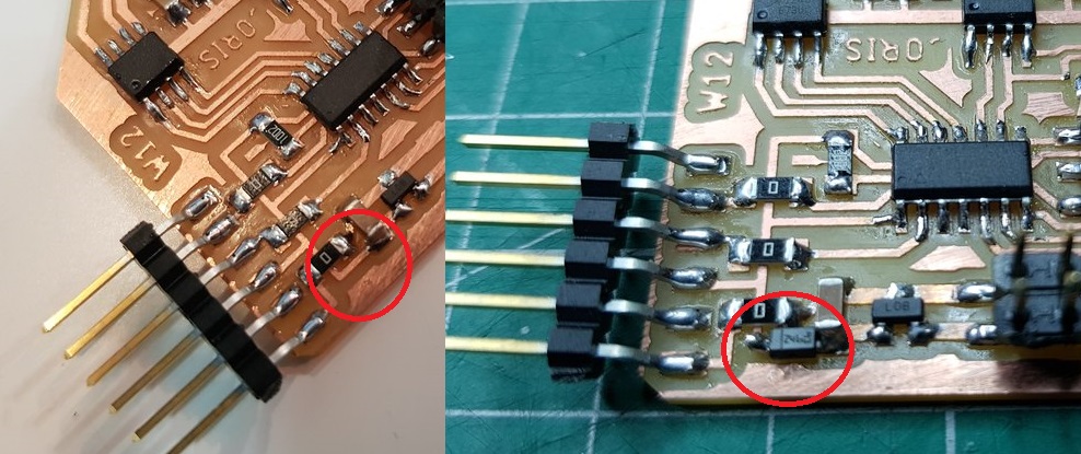
Here is the new result:
Coding
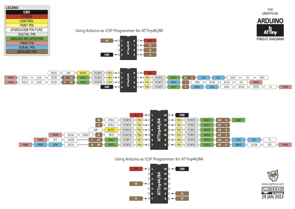
To init the pins used I had to check the MCU pinout
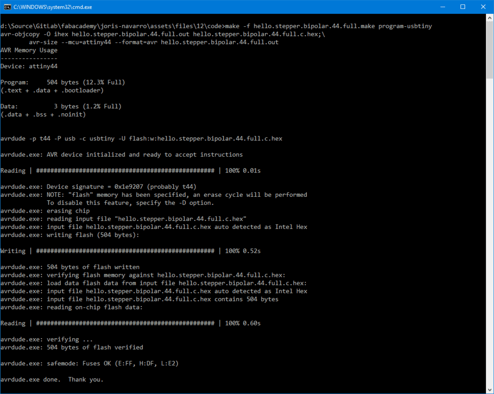
Compiling using AVR toolchain
First of all test using the Neil’s code compiling with avr-toolchain.
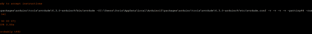
I had a problem using avrdude under windows because the file avrdude.conf where attiny44 is defined was not found.
Compiling and inspecting the command line used by the arduino compiler showed me where to find the file.
Then I copied it to the current dir, and it worked.
Coding using arduino to add the serial command
The code is a mix between the C code from Neil stepper example, and the serial methods I developped on my custom hello board using SoftwareSerial arduino library.
I implemented a simple state machine to memorize the latest command sent and the current state (running, stopped).
Here is arduino code
#include <SoftwareSerial.h>

#define output(directions,pin) (directions |= pin) // set port direction for output
#define set(port,pin) (port |= pin) // set port pin
#define clear(port,pin) (port &= (~pin)) // clear port pin
#define pin_test(pins,pin) (pins & pin) // test for port pin
#define bit_test(byte,bit) (byte & (1 << bit)) // test for bit set

#define bridge_port PORTA // H-bridge port
#define bridge_direction DDRA // H-bridge direction
#define A2 (1 << PA0) // H-bridge output pins
#define A1 (1 << PA1) // "
#define B2 (1 << PA3) // "
#define B1 (1 << PA4) // "
#define on_delay() _delay_us(25) // PWM on time
#define off_delay() _delay_us(5) // PWM off time
#define PWM_count 100 // number of PWM cycles
#define step_count 100 // number of steps

static uint8_t count;

#define RX_PIN  10
#define TX_PIN  9
SoftwareSerial serial(RX_PIN, TX_PIN);

bool stopIt;
static uint8_t turns;

//
// A+ B+ PWM pulse
//
void pulse_ApBp() {
  clear(bridge_port, A2);
  clear(bridge_port, B2);
  set(bridge_port, A1);
  set(bridge_port, B1);
   for (count = 0; count < PWM_count; ++count) {
      set(bridge_port, A1);
      set(bridge_port, B1);
      on_delay();
      clear(bridge_port, A1);
      clear(bridge_port, B1);
      off_delay();
      }
   }

//
// A+ B- PWM pulse
//
void pulse_ApBm() {
  clear(bridge_port, A2);
  clear(bridge_port, B1);
  set(bridge_port, A1);
  set(bridge_port, B2);
   for (count = 0; count < PWM_count; ++count) {
      set(bridge_port, A1);
      set(bridge_port, B2);
      on_delay();
      clear(bridge_port, A1);
      clear(bridge_port, B2);
      off_delay();
      }
   }

//
// A- B+ PWM pulse
//
void pulse_AmBp() {
  clear(bridge_port, A1);
  clear(bridge_port, B2);
  set(bridge_port, A2);
  set(bridge_port, B1);
   for (count = 0; count < PWM_count; ++count) {
      set(bridge_port, A2);
      set(bridge_port, B1);
      on_delay();
      clear(bridge_port, A2);
      clear(bridge_port, B1);
      off_delay();
      }
   }

//
// A- B- PWM pulse
//
void pulse_AmBm() {
  clear(bridge_port, A1);
  clear(bridge_port, B1);
  set(bridge_port, A2);
  set(bridge_port, B2);
   for (count = 0; count < PWM_count; ++count) {
      set(bridge_port, A2);
      set(bridge_port, B2);
      on_delay();
      clear(bridge_port, A2);
      clear(bridge_port, B2);
      off_delay();
      }
   }

//
// clockwise step
//
void step_cw() {
   pulse_ApBp();
   pulse_AmBp();
   pulse_AmBm();
   pulse_ApBm();
   }

//
// counter-clockwise step
//
void step_ccw() {
   pulse_ApBm();
   pulse_AmBm();
   pulse_AmBp();
   pulse_ApBp();
}


void switchMode(int cmd) {
  switch(cmd){
    case 0: turnOff();
            break;
    case 1: goForward();
            break;
    case 2: goBackward();
            break;
    default:
            return;
  }
}

void readSerial(){
  int value =0, input = 0;

  if(serial.available() == 0)
  return;

  switch (serial.available()) {
        /* Serial.available() is the number of bytes waiting.  Convert from
         * ASCII val to an int.  Intentional switch-case fall through below.
        */
        case 3:
          value = serial.read();
          value -= 48;
          value *= 10;
        case 2:
          value += serial.read();
          value -= 48;
          value *= 10;
        case 1:
          input = 0;
          input = serial.read();
          value += input;
          while (serial.available()){serial.read();}
          break;
        default:
          return;
      }
  if(input>0)
  processSerialInput(input);
}

void processSerialInput(int value){
  int mode;
  switch (value) {
    case 'a':
      mode = 0;
      break;
    case 'b':
      mode = 1;
      break;
    case 'c':
      mode = 2;
      break;
    default:
      mode = 0;
      break;
  }
  switchMode(mode);
}

void turnOff(){
  stopIt = true;
}

void goForward(){
  stopIt = false;
  static uint8_t i,j;
  for (i = 0; i < step_count; ++i) {
    if(stopIt) return;
    step_cw();
    readSerial();
  }
  serial.println(turns++);
}

void goBackward(){
  stopIt = false;
  static uint8_t i,j;
  for (i = 0; i < step_count; ++i) {
    if(stopIt) return;
    step_ccw();
    readSerial();
  }
  serial.println(turns--);
}

void setup() {
   //
   // set clock divider to /1
   //
   CLKPR = (1 << CLKPCE);
   CLKPR = (0 << CLKPS3) | (0 << CLKPS2) | (0 << CLKPS1) | (0 << CLKPS0);

   //
   // initialize bridge pins
   //
   clear(bridge_port, A1);
   output(bridge_direction, A1);
   clear(bridge_port, A2);
   output(bridge_direction, A2);
   clear(bridge_port, B1);
   output(bridge_direction, B1);
   clear(bridge_port, B2);
   output(bridge_direction, B2);

   serial.begin(9600);
   serial.println("Ready");
   goForward();
}

void loop() {
  readSerial();
}
And Serial driven stepper motor is working pretty well
check it out.
I use ‘b’ command to turn 2 turns clockwise, and ‘c’ command to turn counterclockwise. And the serial monitor get the number of (2)turns made.
Things to do later
I added pins for input sensors like endstop switches, but I did not get the time to integrate them.
Files to download
Click here to download eagle files
Stay in touch
Hi, I'm
Joris Navarro, from Perpignan (France), a proud dad, a fab director/manager, a teacher, a ceo, a FabAcademy student, but not only. Click here to know more about me.
Check my work for FabAcademy on FabCloud GitLab
@joris.navarro.
Want to say Hi ? Please send me a message.