Computer Controlled Cutting
Week 4 - Computer Controlled Cutting
Here you will find my work description during this fourth week
Class notes
Assignment
Our assignment for this week is: group assignment:
- characterize your lasercutter, making test part(s)that vary cutting settings and dimensions
individual assignment:
- cut something on the vinylcutter
- design, lasercut, and document a parametric press-fit construction kit, accounting for the lasercutter kerf, which can be assembled in multiple ways
Explore laser cut with group
.jpg)
Group is composed by :
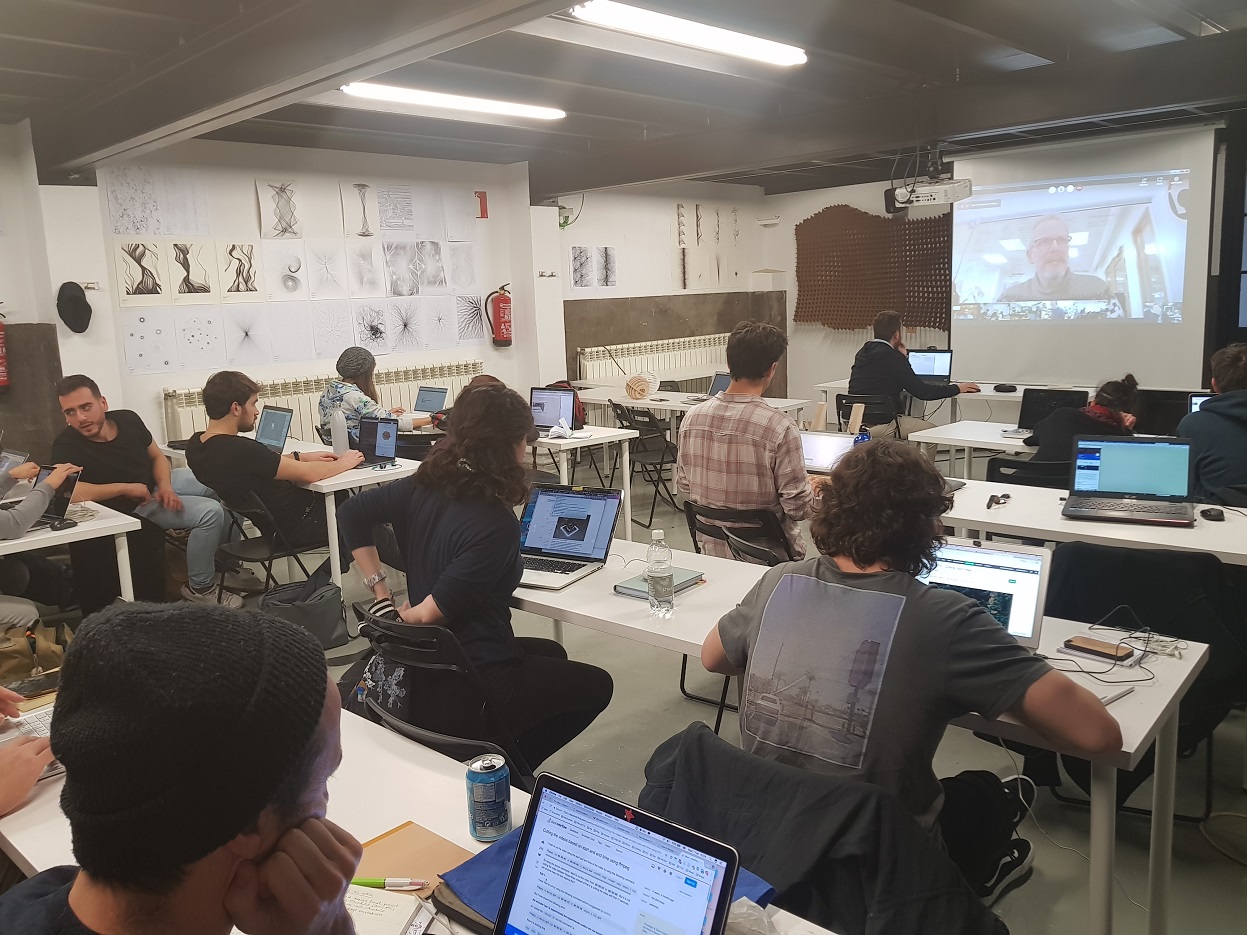
Kris and I will not be a lot available this week so we decide to take it as soon as possible. So on thrusday right after the instructors demo we start doing some tests using the laser cutter. Dorota proposed to design a simple pattern using Illustrator. All of us propose ideas in order to include several cutting and engraving technics.
@santi fu show us the process to use the trotec 400, one of the machine they have in fablab barcelona. You can find here a fully documented presentation of laser cutting technology from Massimo Menichinelli.
Documentation of Trotec 400 Laser cutter
Caracteristics of the Trotec Speedy 400 machine:
- Working area size: 1000 x 610 mm
- Power: 40-120 Watts
- Materials (officla list): wood (5mm), methacrylate or perspex (5mm), cardboard (8mm) , paper, fabrics, non-PVC acrylics and other organic materials.
group assignment
Dorota made a simple design to experiment tha laser operations: engraving, marking, cutting.
.jpg)
Download our Adobe illustrator file
Export file as DXF and upload it to IaaC cloud, because it is forbidden to used USB stick (security concern).
Got to Laser cutters workstation and get your file from network share (cloud). And import it in Rhino (cannot provide Rhino file because it was not saved) already installed.
From Rhino you exec the print command. Select the Trotec Engraver device.
Output type: vector for vectors, raster for bitmaps, which is slow. If there is mied file which contains raster and vector - choose vector.
Scale should be 1:1; set the working area to window, that allows to move the working area relative to the design in Rhino.
Leave a bit of margin around your design. 5mm is a good choice.
Trotec Job Control opens. Press the USB icon to connect to the lasercutter. Play icon appears.
Drag and drop the job from the right side panel. Double click the area to check if it is your job.
Warning: you should define the dimensions of the material area in Rhino print properties.
In TJC you can snap the job canvas to the origin that we set on the machine.
Go to Settings::Material Setup to set up material and colors. Do not check the Auto checkbox
Warning: do not go more than 1.0 for the Speed value for any of the colors.
Define your cutting setting depending on the result you have. Start using predefined values considering your material.
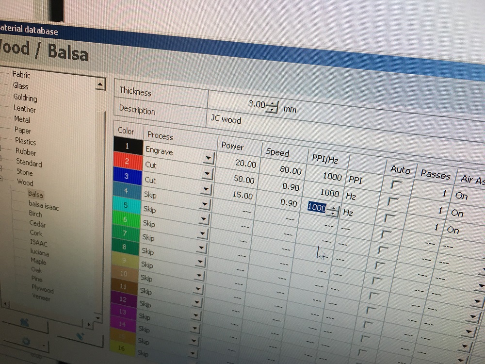
cutting settings
- POWER: the power of the laser, in %, I think, but I am not sure, the machine used has a 120 Watt CO² tube
- Speed: the moves speed, if material is soft you can go fast, but for acrylics or high depth wood you have to go slower.
- PPI/Hz: Frequency of the laser, use 1000 as default value but decrease it that value for plastics because they have a lower melting point. But be carefull the higher you are, the higher is the risk of stting the material on fire.
Use the callipper to define material thickness.
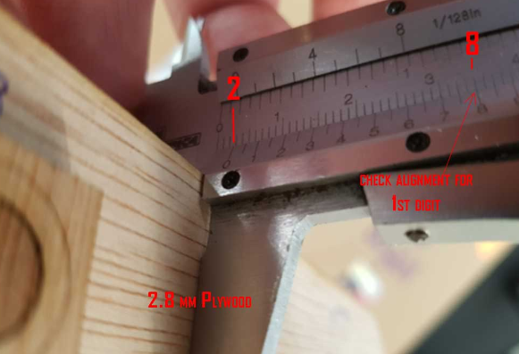
Z calibrate using custom tool because the lens is not the original one.
Repeat until you obtain a nice results.
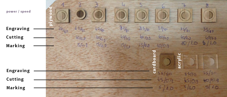
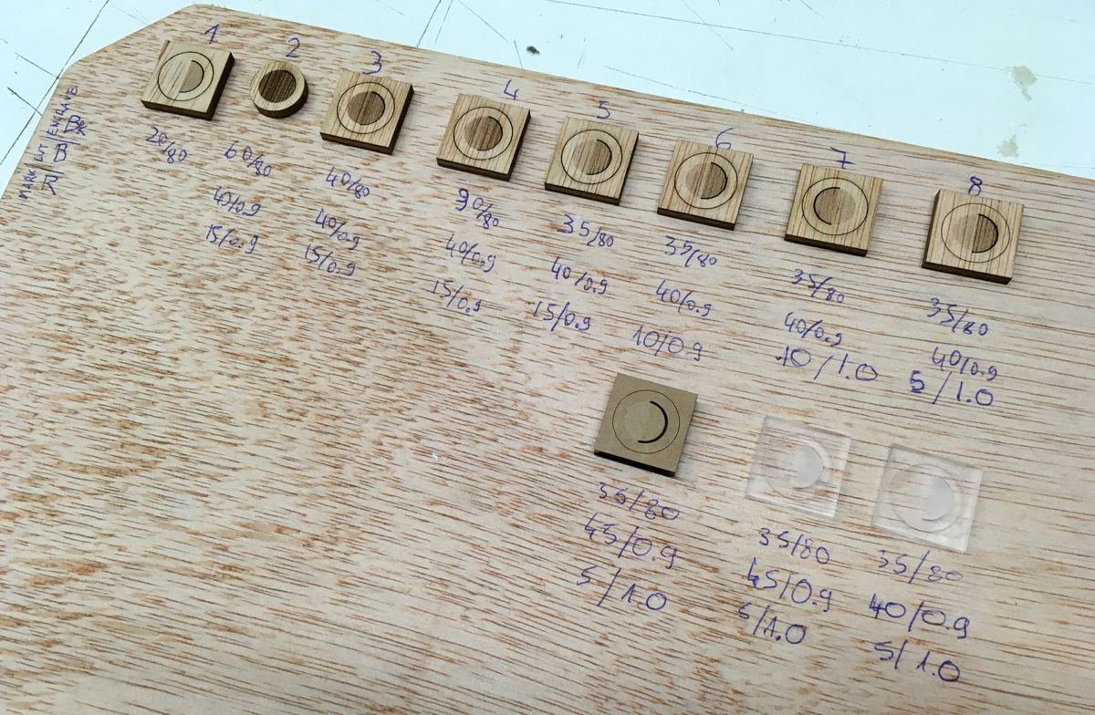
A few hour later we create a board where we glue our experimentations.
My first conculusion:
For me, it was the firts time I use a Trotec laser cutter. I am used to operate on a “Arketype” laser cutter.
My first feedback is on the process used to cut something:
The process, using Rhino, send model to printer, open printer parameters, mesuring material, setting down lenghtes, set up origin, musere material thickness, calibrate Z axis using this ridiculous falling tool, changing settings depending on predefined colors … I am not comparing machines because my “chinese” machine is not comparable with the quality of the trotec, but the trotec process is so complex comparing to the one I am use to use. I mean auto leveling is great, define your setting for your colors (you have to known your setting depending on your material), uppload to the machine, move your start point wherever you want, show piece area, start process is a way musch easier. But I cannot deny the result is nicer on the trotec.
By the way, I have to spend more time on this machine to be more confident using it. But by experience technic of laser cutting are similar and I was not surprised by our experientations but it was a good exercice.
Vinyle cut something
the machines
Roland GS24 Camm-1
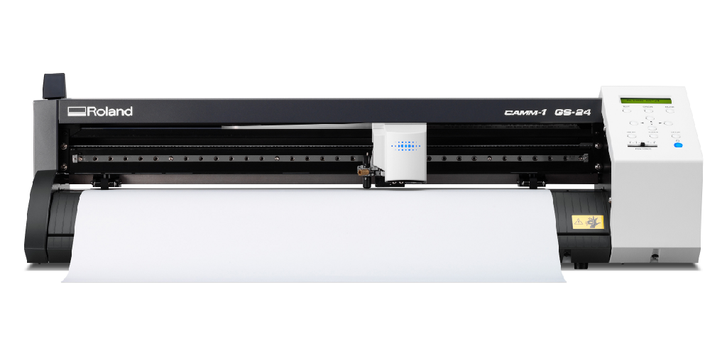
- Official page
- Documentation
- Working area : 580 x 1600 mm - because of the wheels that limit width
- Max force of the knife : 240gf
- Softwares : Inkscape (Roland printer driver) - CutStudio
- Tutorial on how to use the Roland GS24 - Vinyl cutter
Silhouette Camo (not used for this assignment)
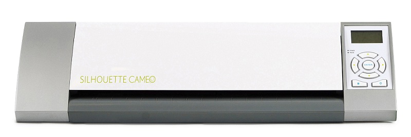
- Official page
- Documentation (FR)
- Working area : 300 x 1600 mm - because of the wheels that limit width
- Max force of the knife : 210gf
- Softwares : Silhouette Studio
Assignement
I am quietly confortable with vinyle plotter. I already created signs, stencils, stickers, flock for t-shirts using my Roland GS24 and Silhouette Cameo.
.jpg)
This is what I have done for this assignement.
-
Get an Image from internet, I choose the FabAcademy Logo, and import it in Inkscape.
-
Vectorize the bitmap using Path->Vectorize tool (don’t froget to change the threshold value if you want to vectorize light colors)
.jpg)
-
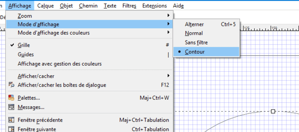
You can use Menu->Display->Outlines to check the pathes created by the tool.
-
I use the machine driver (seen as a printer) to send commands to the machine.
IMPORTANT It was not working, machine received commands but do nothing !!?! $§ù Finally it was because I forgot ot set up a oultline thikness, with no thickness and no backgroud, nothing to print !
IMPORTANT Using thing drive is a bit confusing due to roll orientation and origin. Was using a roll behind the machine, the origin is 1600mm from the start, so I am used to set rotate 90° conter clockwise so orgin of the model bottom left is bottom right in the machine.
- Introduce your material (A old dry white sticker I have) Machine will tell you working area, be sure your model fits in it.
.jpg)
- Test the force you are going to use, I use 90gf for that vinyle. Pressing Test button will cut this patern, try to remove cut part. If it is not easy change force setting.
.jpg)
- Cut using “Print” command, I usually use the plastic blade first to check the position.
Check the video of cutting vinyle:
- You can use the provided tools or a cutter remove parts you don’t want (remove letters for exemple if you want a stencil).
.jpg)
- apply transfer film to detach lasting part, and paste it where you want (clean surface befor paste). My laptop in my case
.jpg)
- Use a specific tool or a credit card to remove bubles (on big stickers, you probably have to be experimented to past it correcly)
Pro Tip Use glass cleaning product before paste, you will be able to move the sticker at the right place alignement, position. This liquid contains ethanol that will evaporate.
.jpg)
And Voilà !!
Click here to download the Inkscape file
*Edit 2018 06 01*: I should have made my own design, so let's see a brand new design used for the final project using Inkscape.
I like to draw using the outline view. That way we can see the curves.
Draw basic shape using the pen, we will tune all shapes later
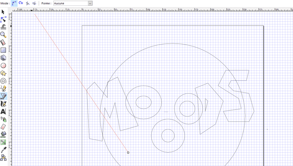
Trying to find a nice design
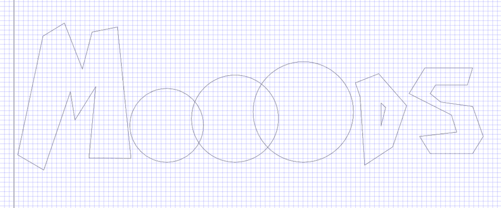
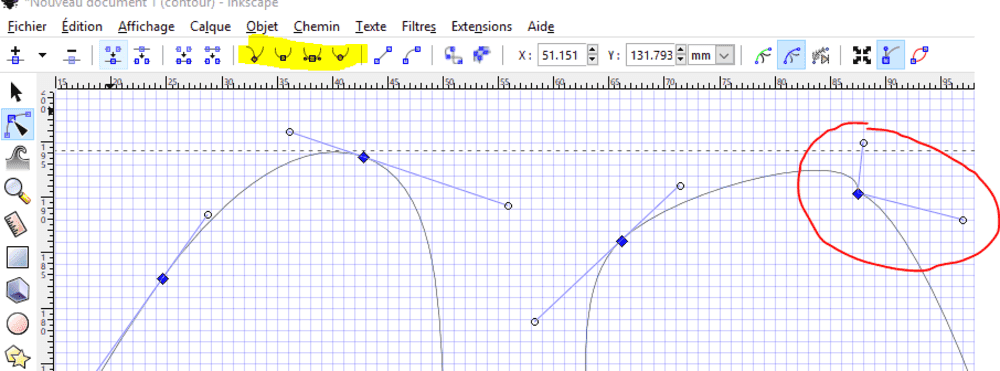
Playing with Beziers curves.
Finding inspiration online: I found a cool font called Lactosa. But it is not a free to use font.
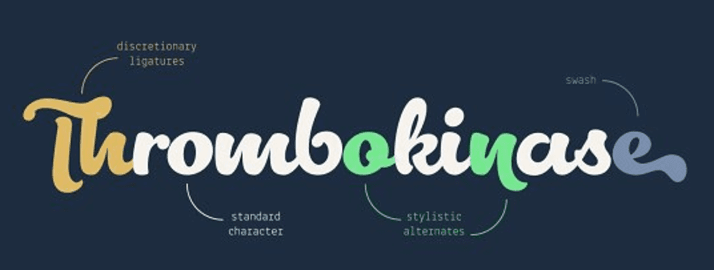
I realized using beziers curves somithing close than the font.
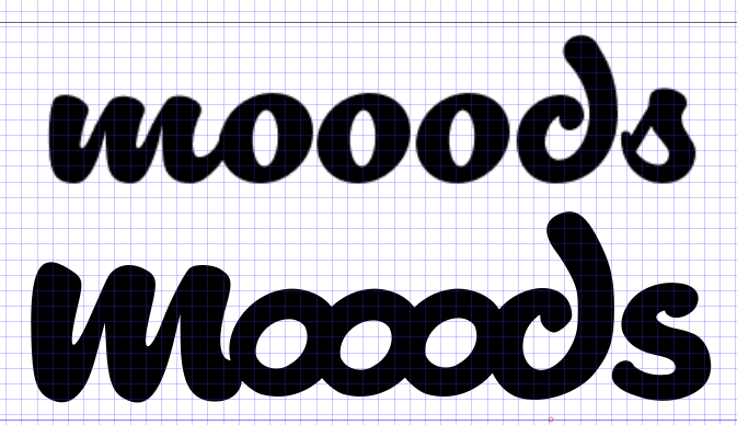
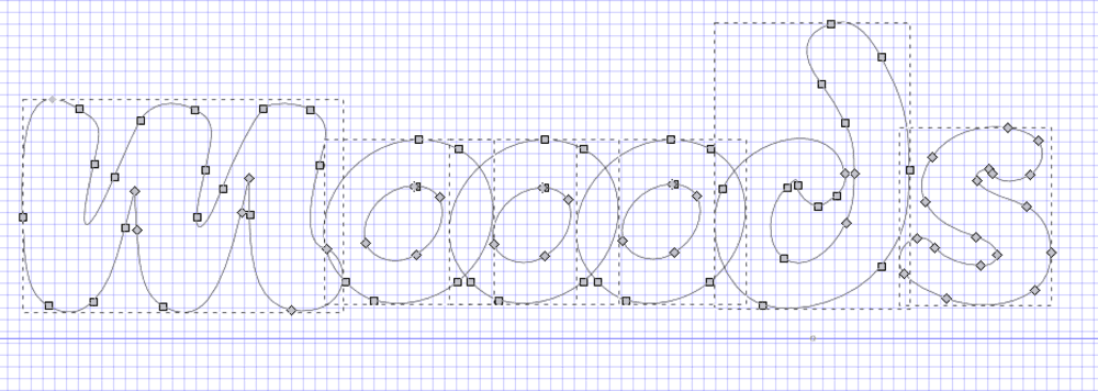
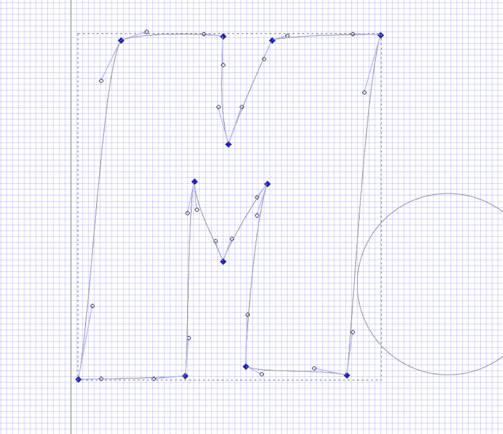
Using Union to join curves.
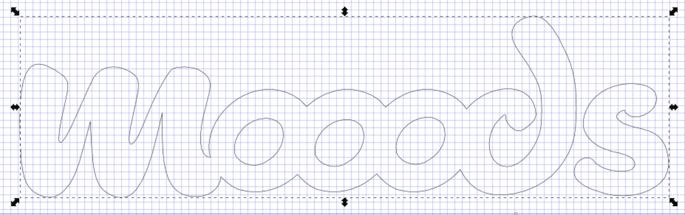
Here is the result.
As I want to use it for final project presentation I decided to purchase the complete version of Lactosa font from Creative Market
Press fit
Parametric modeling : Discovering Rhino with Grasshopper
First thing I did is watching video on how to get started with grasshopper
One of my goal for fabacademy is to dig more into design software, especially parametric and generative modeling using grassohopper.
I started exploring the tools and their behaviours. Hopefully some students and instructors have helped me when I was stuck. I know the defintion I made were not the most efficient but step by step I started learning how to use this awesome software.
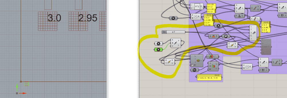
Model parametric calibration model using GH
How I designed the kerfing model:
- I defined the variables I will need for the desin, those parameters are the keys of the design. We will test kerf width every 0.05 mm. We can specify the thickness of the material the number of slots, the space between slots, the height and width of the test parts.
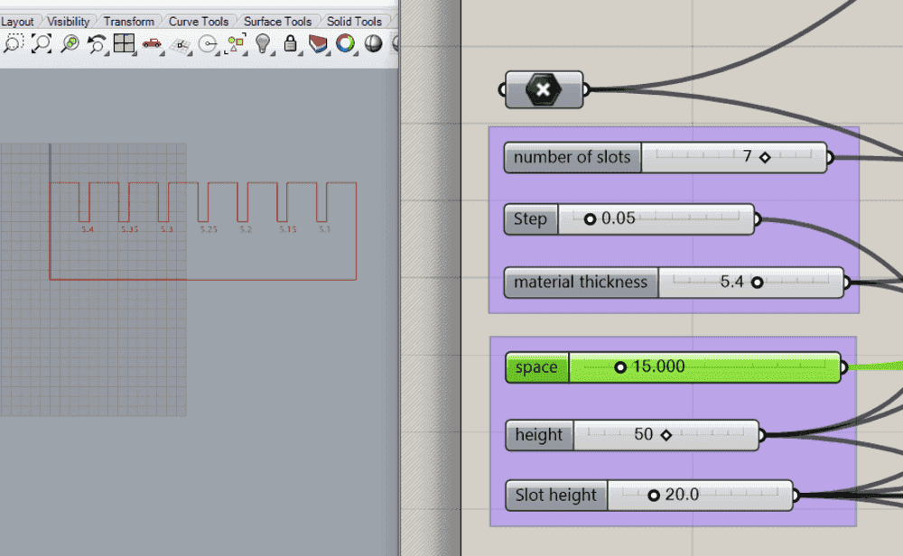
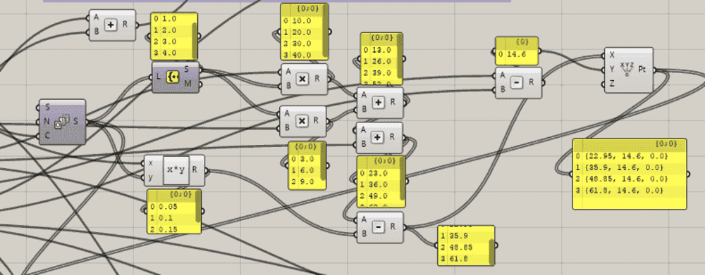
- I draw lines using coordinates computed with the kerf I wanted + a delta.
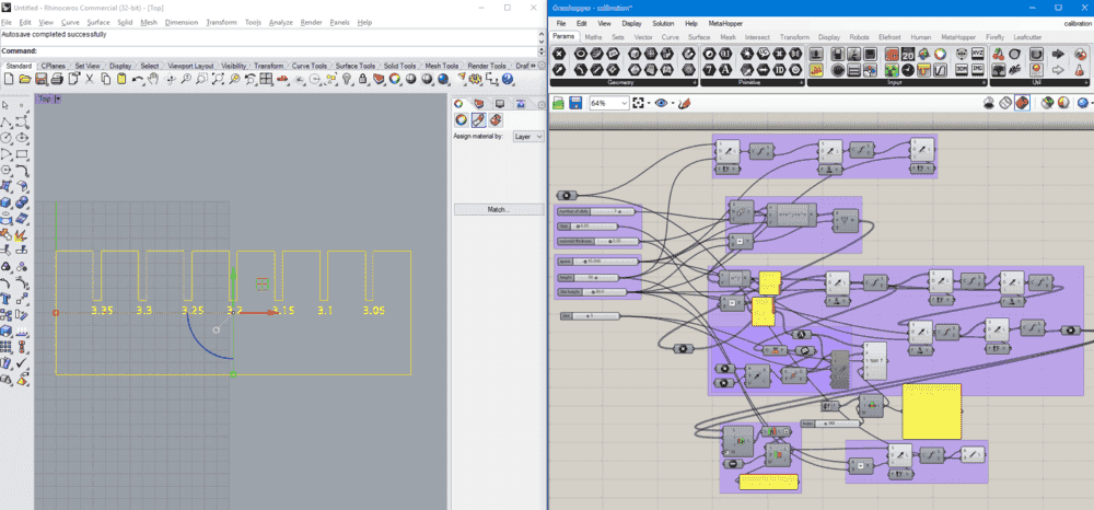
- I used groups to try to indentify the functions (not in the followinf pic). Using panel as a debug option is usefull to visualize data workflow.
- Finally I add text to the model, that was not an easy part.
First conclusion:
I like the potentiel of this software and the way we manage data. Even if understanding how collections, trees, graphes, branches … were a bit confusing. But a grasshopper defintion is a visual mess. We can use clusters to regroup commands but all those wires make it difficult to read.
Click here to download the grasshopper file
Kerfing tests
Once I have defined my calibration kerfing tests model, I can do some tests to determine kerfing value.
Arketype 100w CO² laser cutter specification:
- Working area: 600 x 900 mm
- Power: 15-100W
- Cutting max speed : 150 mm/s
- Engraving max speed : 600 mm/s
- Frequency : 2000 (not adjustable)
- Z-Auto focus.
- Material max height: 300 mm
- Materials (unofficla list): wood (10mm), cardboard , paper, fabrics, non-PVC acrylics and other organic materials, PMMA (10mm).
- Software : LaserCut (not open source)

Process
- Mesure and report value on model, then generate DXF to import in Lasercut (software used for Arketype Laser cutter)
.jpg)
- do some test to adjust power and speed depending on material used
.jpg)
.jpg)
- try with different materials
.jpg)
.jpg)
Values used for cutting
| Material | Speed (mm/s) | power |
|---|---|---|
| 5mm plywood | 25 | 60 |
| 4.5 cardboard | 50 | 50 |
| 3mm pmma | 25 | 60 |
| 3mm mdf | 35 | 60 |
I haven’t tried cutting this model with the Barcelona fabalab trotec laser cutter, but with the arketype, I can say that the kerf value is between 0.12 and 0.14 mm.
ProTip Use Shift+drag and drop to set several inputs to a box. For example, I wanted to join generated lines to “Join curves” box but I cannot set multiple lines. Santi showed me that we can do it using shift+drag and drop all lines to this box
Plugin To convert text to curves I had to use a plugin called “Bower bird”
Press-fit model
What I wanted to do is having a fully customizable parametic model to create multiple shapes with press fit slots in order to create a kit to build what we want with press fit pieces.
So I start designing (discovering parametric design) using Rhino with grasshopper plugin.
I spent a lot of time on this design because I am not familiar with GH, but with time I start having results.
Back to grasshopper trying to create a generic pressfit design of parts you can assemble to create your object.
Behind the design
Be able to choose how many side you want, the size of the model, the slot locations, the kerf, I wanted this model as parametric as I can. And this is what I did.
The process was basically the same, first declare the variables, like the nombre of faces of the 2D geometry, and a radius (size) of the part. the define the kerf to be set each sides of the generated slots. There is also a variable to determine if you want the slot at the middle of an edge or if you want them at the starting and ending points of the edge.
As you can see, the definition is a mess, and is hard to explain. I invite you to dowload the file and dig into each groupe, activate boxes, play with cursors to discover what I did.
.jpg)
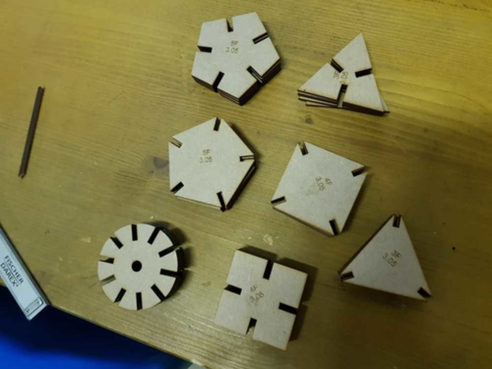
Here you can see an example of what you can do with 5 of each parts.
.jpg)
Click here to download the grasshopper file
Extra : Plasma cutting
In FabLab Perpignan we are building our CNC plasma cutter. This machine is still in developpement, but it is the occasion to test it and to show plasma cnc cutting.
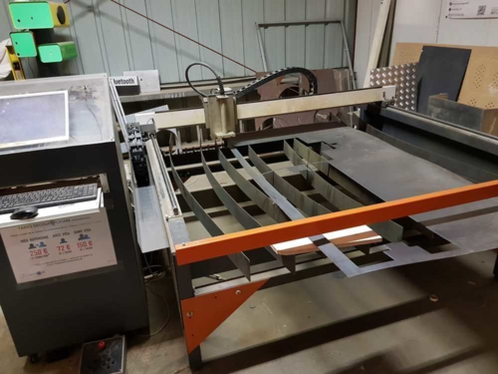
-
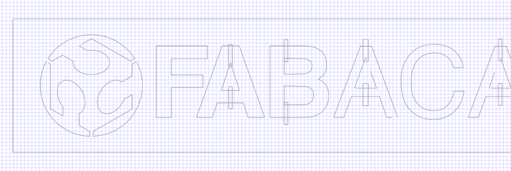
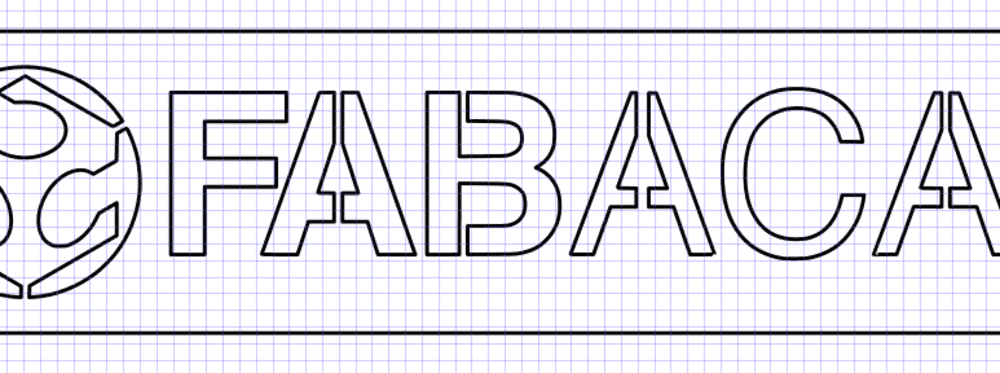
I used the same model, but resized to fit in a 500mm width rectangle.
-
I had to change it a little bit to avoid falling parts
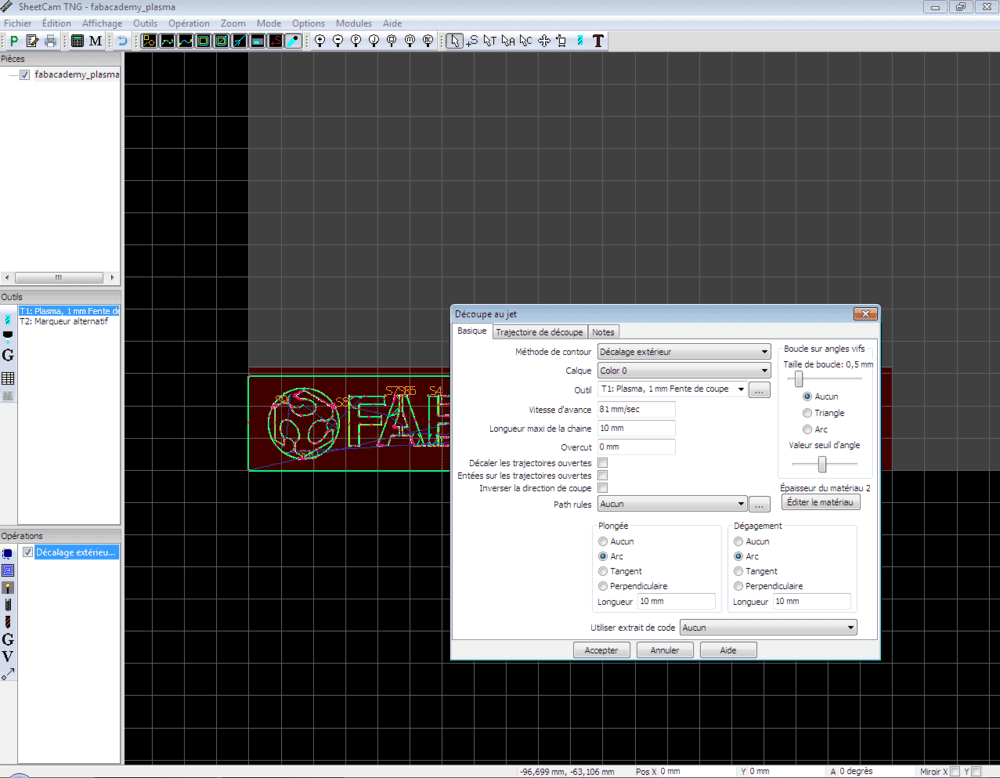
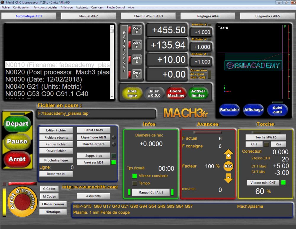
- We use SheetCAM to generate the g-code, and Mach3 to interpret it.
Check the video of plasma cutting :
- Unfortunatly the result was not the one we expected and we clearly see that we lost steps on Y axis during the cutting process (maybe have to fix high accelerations), but that’s a thing.
.jpg)
Stay in touch
Hi, I'm
Joris Navarro, from Perpignan (France), a proud dad, a fab director/manager, a teacher, a ceo, a FabAcademy student, but not only. Click here to know more about me.
Check my work for FabAcademy on FabCloud GitLab
@joris.navarro.
Want to say Hi ? Please send me a message.