Final Project: A Cat Friendly Bench.
All documentation related to the final project is distributed among these htlml pages:- A short presentation of my final project (Click here)
- All documentation of the final project production:
- Final project CNC Machining (Click here):
- Final project electronics design and production: Fabduino + Handmade Led Stripe (We are here)
- Final project composite: A half of an X tube (Click here)
** CNC Machining (I) DM: A cat friendly bench (Click here)
**CNC Machining (II) FOAM: An X tube mold (Click here)
Final Project: A Cat Friendly Bench. Electronics design and production.
1. Fabduino ATmega168A 16MHz:
1.1. Fabduino ATmega168A 16MHz Electronics design and production files:
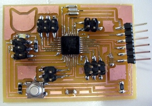
1.2. Fabduino description:
* Fabduino ATmega168A 16MHz Components:
- S1 Switch
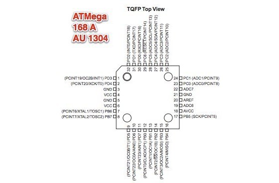
- ATmega168A
- XTAl 16MHz
- C1 1uF
- C2 0,1 uF
- R1 1k
- R2 10k
- R3 0k
- 3 header ISP (6 pins)
- 2 header ISP (4 pins)
- FTDI connector
- D1 Led
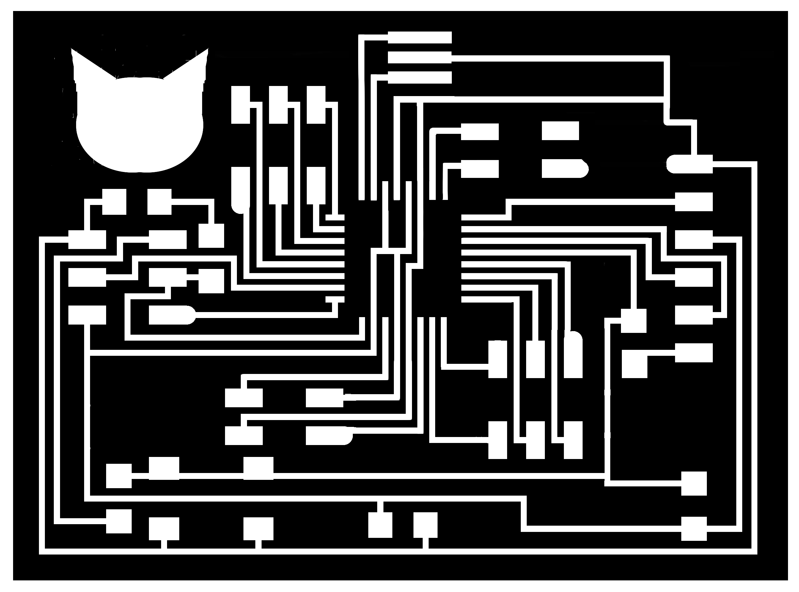
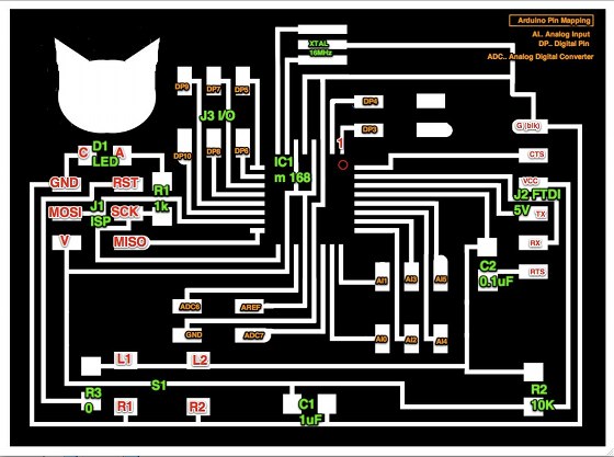
* Fabduino ATmega168A 16MHz Pin Mapping.
From this image of Anna's fabduino I have prepared the Pin Mapping of the Fabduino following this ATMega 168 Arduino Pin Mapping published at arduino.cc website.
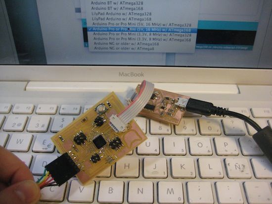
1.3. Fabduino Programming:
I followed Anna's tutorial hello arduino and programmed the board with out any problem.
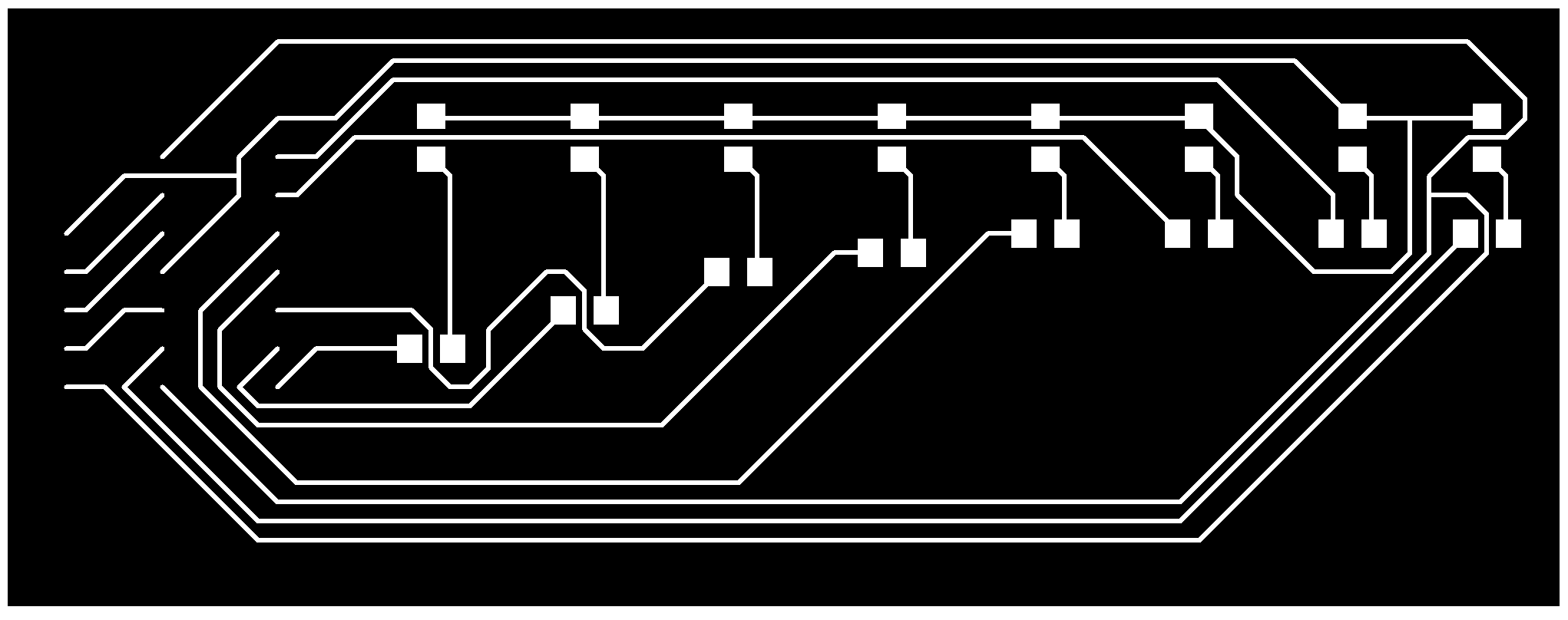
2. Handmade Led Stripe:
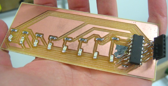 Handmade Led Stripe with 74HC595 8 bit shift register
2.1. How to make a Handmade Led Stripe. Some research:
I want leds to simulate movement. There are several solutions for it. Below there are some of these solutions described:
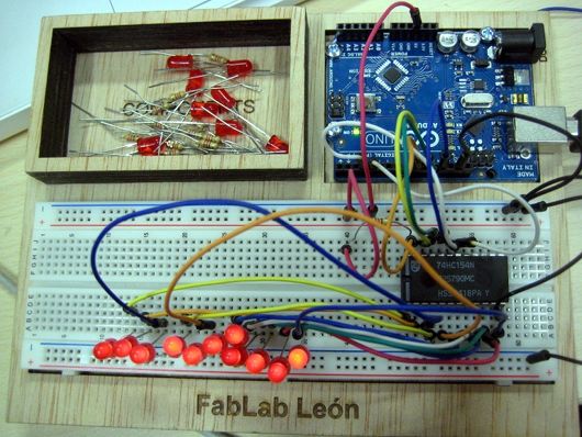
* Demultiplexer 74HCT154N. 4-16 outputs.
I read about Some Multiplexer/Demultiplexer here; and started making tests with an arduino board and a protoboard:
 74HCT154N Datasheet
  /*
  Blink
  Turns on an LED on for one second, then off for one second, repeatedly.

  This example code is in the public domain.
 */

void setup() {
  // initialize the digital pin as an output.
  // Pin 13 has an LED connected on most Arduino boards:
   pinMode(9, OUTPUT);
    pinMode(10, OUTPUT);
     pinMode(11, OUTPUT);
      pinMode(12, OUTPUT);
  pinMode(3, OUTPUT);
 digitalWrite(3, LOW);
pinMode(4, OUTPUT);
digitalWrite(4, LOW);
}

void loop() {
  digitalWrite(9, LOW);   // set the LED on
  digitalWrite(10, LOW);    // set the LED off
  digitalWrite(11, LOW);    // set the LED off
  digitalWrite(12, LOW);    // set the LED off
  delay(300);              // wait for a second
  digitalWrite(9, HIGH);   // set the LED on
  digitalWrite(10, LOW);    // set the LED off
  digitalWrite(11, LOW);    // set the LED off
  digitalWrite(12, LOW);    // set the LED off
  delay(300);              // wait for a second
  digitalWrite(9, LOW);   // set the LED on
  digitalWrite(10, HIGH);    // set the LED off
  digitalWrite(11, LOW);    // set the LED off
  digitalWrite(12, LOW);    // set the LED off
  delay(300);              // wait for a second
  digitalWrite(9, HIGH);   // set the LED on
  digitalWrite(10, HIGH);    // set the LED off
  digitalWrite(11, LOW);    // set the LED off
  digitalWrite(12, LOW);    // set the LED off
  delay(300);              // wait for a second
  digitalWrite(9, LOW);   // set the LED on
  digitalWrite(10, LOW);    // set the LED off
  digitalWrite(11, HIGH);    // set the LED off
  digitalWrite(12, LOW);    // set the LED off
  delay(300);              // wait for a second
  digitalWrite(9, HIGH);   // set the LED on
  digitalWrite(10, LOW);    // set the LED off
  digitalWrite(11, HIGH);    // set the LED off
  digitalWrite(12, LOW);    // set the LED off
  delay(300);              // wait for a second
  digitalWrite(9, LOW);   // set the LED on
  digitalWrite(10, HIGH);    // set the LED off
  digitalWrite(11, HIGH);    // set the LED off
  digitalWrite(12, LOW);    // set the LED off
  delay(300);              // wait for a second
  digitalWrite(9, HIGH);   // set the LED on
  digitalWrite(10, HIGH);    // set the LED off
  digitalWrite(11, HIGH);    // set the LED off
  digitalWrite(12, LOW);    // set the LED off
  delay(300);              // wait for a second
  digitalWrite(9, LOW);   // set the LED on
  digitalWrite(10, LOW);    // set the LED off
  digitalWrite(11, LOW);    // set the LED off
  digitalWrite(12, HIGH);    // set the LED off
  delay(300);              // wait for a second
  digitalWrite(9, HIGH);   // set the LED on
  digitalWrite(10, LOW);    // set the LED off
  digitalWrite(11, LOW);    // set the LED off
  digitalWrite(12, HIGH);    // set the LED off
  delay(300);              // wait for a second
  digitalWrite(9, LOW);   // set the LED on
  digitalWrite(10, HIGH);    // set the LED off
  digitalWrite(11, LOW);    // set the LED off
  digitalWrite(12, HIGH);    // set the LED off
  delay(300);              // wait for a second
  digitalWrite(9, HIGH);   // set the LED on
  digitalWrite(10, HIGH);    // set the LED off
  digitalWrite(11, LOW);    // set the LED off
  digitalWrite(12, HIGH);    // set the LED off
  delay(300);
}
*74HC595 8 bit shift register. This is the one I am finally using.
It lets expand on the digital outputs we have on our mictrocontroller. Each one of these 74HC595s can act like 8 more digital outputs. All info: http://bildr.org/2011/02/74hc595/ and 74HC595 datasheet here
.
int SER_Pin = 8;   //pin 14 on the 75HC595
int RCLK_Pin = 9;  //pin 12 on the 75HC595
int SRCLK_Pin = 10; //pin 11 on the 75HC595

//How many of the shift registers - change this
 #define number_of_74hc595s 1

//do not touch
 #define numOfRegisterPins number_of_74hc595s * 8

boolean registers[numOfRegisterPins];

void setup(){
  pinMode(SER_Pin, OUTPUT);
  pinMode(RCLK_Pin, OUTPUT);
  pinMode(SRCLK_Pin, OUTPUT);


  //reset all register pins
  clearRegisters();
  writeRegisters();
}


//set all register pins to LOW
void clearRegisters(){
  for(int i = numOfRegisterPins - 1; i >=  0; i--){
     registers[i] = LOW;
  }
}


//Set and display registers
//Only call AFTER all values are set how you would like (slow otherwise)
void writeRegisters(){

  digitalWrite(RCLK_Pin, LOW);

  for(int i = numOfRegisterPins - 1; i >=  0; i--){
    digitalWrite(SRCLK_Pin, LOW);

    int val = registers[i];

    digitalWrite(SER_Pin, val);
    digitalWrite(SRCLK_Pin, HIGH);

  }
  digitalWrite(RCLK_Pin, HIGH);

}

//set an individual pin HIGH or LOW
void setRegisterPin(int index, int value){
  registers[index] = value;
}


void loop(){
setRegisterPin(1, HIGH);
  setRegisterPin(2, LOW);
  setRegisterPin(3, LOW);
  setRegisterPin(4, LOW);
  setRegisterPin(5, LOW);
  setRegisterPin(6, LOW);
  setRegisterPin(7, LOW);
  writeRegisters();
  delay (100);

  setRegisterPin(1, LOW);
  setRegisterPin(2,  HIGH);
  setRegisterPin(3, LOW);
  setRegisterPin(4, LOW);
  setRegisterPin(5, LOW);
  setRegisterPin(6, LOW);
  setRegisterPin(7, LOW);
  writeRegisters();
   delay (100);
  setRegisterPin(1, LOW);
  setRegisterPin(2, LOW);
  setRegisterPin(3, HIGH);
  setRegisterPin(4, LOW);
  setRegisterPin(5, LOW);
  setRegisterPin(6, LOW);
  setRegisterPin(7, LOW);
   writeRegisters();
   delay (100);

     setRegisterPin(1, LOW);
  setRegisterPin(2, LOW);
  setRegisterPin(3, LOW);
  setRegisterPin(4, HIGH);
  setRegisterPin(5, LOW);
  setRegisterPin(6, LOW);
  setRegisterPin(7, LOW);
   writeRegisters();
   delay (100);

    setRegisterPin(1, LOW);
  setRegisterPin(2, LOW);
  setRegisterPin(3, LOW);
  setRegisterPin(4, LOW);
  setRegisterPin(5, HIGH);
  setRegisterPin(6, LOW);
  setRegisterPin(7, LOW);
   writeRegisters();
   delay (100);
    setRegisterPin(1, LOW);
  setRegisterPin(2, LOW);
  setRegisterPin(3, LOW);
  setRegisterPin(4, LOW);
  setRegisterPin(5, LOW);
  setRegisterPin(6, HIGH);
  setRegisterPin(7, LOW);
   writeRegisters();
   delay (100);

      setRegisterPin(1, LOW);
  setRegisterPin(2, LOW);
  setRegisterPin(3, LOW);
  setRegisterPin(4, LOW);
  setRegisterPin(5, LOW);
  setRegisterPin(6, LOW);
  setRegisterPin(7, HIGH);
   writeRegisters();
   delay (100);

   setRegisterPin(1, LOW);
  setRegisterPin(2, LOW);
  setRegisterPin(3, LOW);
  setRegisterPin(4, LOW);
  setRegisterPin(5, LOW);
  setRegisterPin(6, LOW);
  setRegisterPin(7, LOW);

   writeRegisters();
   delay (100);
   //MUST BE CALLED TO DISPLAY CHANGES
  //Only call once after the values are set how you need.
}
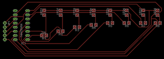
Once everything works on the arduino board I made the final design on Eagle.
2.2. Handmade Led Stripe Electronics design and production files:
3. Ultrasonic Sensor
Utrasonic sensor HC - SR04. Datasheet: http://users.ece.utexas.edu/~valvano/Datasheets/HCSR04b.pdf
Code distance:
/*
 HC-SR04 Ping distance sensor]
 VCC to arduino 5v GND to arduino GND
 Echo to Arduino pin 13 Trig to Arduino pin 12
 More info at: http://goo.gl/kJ8Gl
 */

#define trigPin 5
#define echoPin 4

void setup() {
  Serial.begin (9600);
  pinMode(trigPin, OUTPUT);
  pinMode(echoPin, INPUT);
}

void loop() {
  int duration, distance;
  digitalWrite(trigPin, HIGH);
  delayMicroseconds(1000);
  digitalWrite(trigPin, LOW);
  duration = pulseIn(echoPin, HIGH);
  distance = (duration/2) / 29.1;
  if (distance >= 200 || distance <= 0){
    Serial.println("Out of range");
  }
  else {
    Serial.print(distance);
    Serial.println(" cm");
  }
  delay(500);
}
Other interesting links: http://arduinobasics.blogspot.com.es/2012/11/arduinobasics-hc-sr04-ultrasonic-sensor.html
http://trollmaker.com/article3/arduino-and-hc-sr04-ultrasonic-sensor
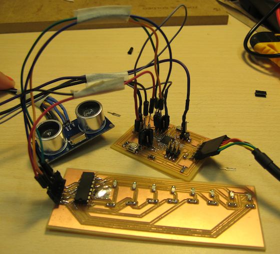
4. Everything working together: ultrasonic sensor + handmade led stripe
4.1 First test. I tested everything together on the arduino board, to test the code and all the integration of components.
/*
27 mayo 2013 Fab Academy Fab Lab Leon

This code is a mix between:
* HC-SR04 Ping distance sensor]
 VCC to arduino 5v GND to arduino GND
 Echo to Arduino pin 13 Trig to Arduino pin 12
 More info at: http://goo.gl/kJ8Gl

* An example of the 74HC595 8 bit shift register that has been found here http://bildr.org/2011/02/74hc595/
 */

//ultrasonic sensor pins
#define trigPin 5
#define echoPin 4

//74HC595 Pins that connects to Arduino
int SER_Pin = 8;   //pin 14 on the 75HC595
int RCLK_Pin = 9;  //pin 12 on the 75HC595
int SRCLK_Pin = 10; //pin 11 on the 75HC595

//How many of the shift registers - change this
 #define number_of_74hc595s 1

 //do not touch
 #define numOfRegisterPins number_of_74hc595s * 8
 boolean registers[numOfRegisterPins];


void setup() {
  Serial.begin (9600);
  pinMode(trigPin, OUTPUT);
  pinMode(echoPin, INPUT);

   pinMode(SER_Pin, OUTPUT);
  pinMode(RCLK_Pin, OUTPUT);
  pinMode(SRCLK_Pin, OUTPUT);


  //reset all register pins 74hc595
  clearRegisters();
  writeRegisters();
}


//set all register pins to LOW
void clearRegisters(){
  for(int i = numOfRegisterPins - 1; i >=  0; i--){
     registers[i] = LOW;
  }
}

//Set and display registers
//Only call AFTER all values are set how you would like (slow otherwise)
void writeRegisters(){

  digitalWrite(RCLK_Pin, LOW);

  for(int i = numOfRegisterPins - 1; i >=  0; i--){
    digitalWrite(SRCLK_Pin, LOW);

    int val = registers[i];

    digitalWrite(SER_Pin, val);
    digitalWrite(SRCLK_Pin, HIGH);

  }
  digitalWrite(RCLK_Pin, HIGH);

}

//set an individual pin HIGH or LOW
void setRegisterPin(int index, int value){
  registers[index] = value;
}

void loop() {
  int duration, distance;
  digitalWrite(trigPin, HIGH);
  delayMicroseconds(1000);
  digitalWrite(trigPin, LOW);
  duration = pulseIn(echoPin, HIGH);
  distance = (duration/2) / 29.1;
  if (distance <20 ) {
    // when the cat gets into the house/tube leds start lighting
    setRegisterPin(1, HIGH);
  setRegisterPin(2, LOW);
  setRegisterPin(3, LOW);
  setRegisterPin(4, LOW);
  setRegisterPin(5, LOW);
  setRegisterPin(6, LOW);
  setRegisterPin(7, LOW);
  writeRegisters();
  delay (100);

  setRegisterPin(1, LOW);
  setRegisterPin(2,  HIGH);
  setRegisterPin(3, LOW);
  setRegisterPin(4, LOW);
  setRegisterPin(5, LOW);
  setRegisterPin(6, LOW);
  setRegisterPin(7, LOW);
  writeRegisters();
   delay (100);
  setRegisterPin(1, LOW);
  setRegisterPin(2, LOW);
  setRegisterPin(3, HIGH);
  setRegisterPin(4, LOW);
  setRegisterPin(5, LOW);
  setRegisterPin(6, LOW);
  setRegisterPin(7, LOW);
   writeRegisters();
   delay (100);

     setRegisterPin(1, LOW);
  setRegisterPin(2, LOW);
  setRegisterPin(3, LOW);
  setRegisterPin(4, HIGH);
  setRegisterPin(5, LOW);
  setRegisterPin(6, LOW);
  setRegisterPin(7, LOW);
   writeRegisters();
   delay (100);

    setRegisterPin(1, LOW);
  setRegisterPin(2, LOW);
  setRegisterPin(3, LOW);
  setRegisterPin(4, LOW);
  setRegisterPin(5, HIGH);
  setRegisterPin(6, LOW);
  setRegisterPin(7, LOW);
   writeRegisters();
   delay (100);
    setRegisterPin(1, LOW);
  setRegisterPin(2, LOW);
  setRegisterPin(3, LOW);
  setRegisterPin(4, LOW);
  setRegisterPin(5, LOW);
  setRegisterPin(6, HIGH);
  setRegisterPin(7, LOW);
   writeRegisters();
   delay (100);

      setRegisterPin(1, LOW);
  setRegisterPin(2, LOW);
  setRegisterPin(3, LOW);
  setRegisterPin(4, LOW);
  setRegisterPin(5, LOW);
  setRegisterPin(6, LOW);
  setRegisterPin(7, HIGH);
   writeRegisters();
   delay (100);

   setRegisterPin(1, LOW);
  setRegisterPin(2, LOW);
  setRegisterPin(3, LOW);
  setRegisterPin(4, LOW);
  setRegisterPin(5, LOW);
  setRegisterPin(6, LOW);
  setRegisterPin(7, LOW);

   writeRegisters();
   delay (100);
  }


  if (distance >= 200 || distance <= 0){
    Serial.println("Out of range");
  }
  else {
    Serial.print(distance);
    Serial.println(" cm");

  delay(500);
}
}
4.2. Finally I used my own fabduino and the handmade led stripe:
/*
27 mayo 2013 Fab Academy Fab Lab Leon

This code is a mix between:
* HC-SR04 Ping distance sensor]
 VCC to arduino 5v GND to arduino GND
 Echo to Arduino pin 13 Trig to Arduino pin 12
 More info at: http://goo.gl/kJ8Gl

* An example of the 74HC595 8 bit shift register that has been found here http://bildr.org/2011/02/74hc595/
 */

//ultrasonic sensor pins
#define trigPin 5
#define echoPin 4

//74HC595 Pins that connects to Arduino
int SER_Pin = 8;   //pin 14 on the 75HC595
int RCLK_Pin = 9;  //pin 12 on the 75HC595
int SRCLK_Pin = 10; //pin 11 on the 75HC595

//How many of the shift registers - change this
 #define number_of_74hc595s 1

 //do not touch
 #define numOfRegisterPins number_of_74hc595s * 8
 boolean registers[numOfRegisterPins];


void setup() {
  Serial.begin (9600);
  pinMode(trigPin, OUTPUT);
  pinMode(echoPin, INPUT);

   pinMode(SER_Pin, OUTPUT);
  pinMode(RCLK_Pin, OUTPUT);
  pinMode(SRCLK_Pin, OUTPUT);


  //reset all register pins 74hc595
  clearRegisters();
  writeRegisters();
}


//set all register pins to LOW
void clearRegisters(){
  for(int i = numOfRegisterPins - 1; i >=  0; i--){
     registers[i] = LOW;
  }
}

//Set and display registers
//Only call AFTER all values are set how you would like (slow otherwise)
void writeRegisters(){

  digitalWrite(RCLK_Pin, LOW);

  for(int i = numOfRegisterPins - 1; i >=  0; i--){
    digitalWrite(SRCLK_Pin, LOW);

    int val = registers[i];

    digitalWrite(SER_Pin, val);
    digitalWrite(SRCLK_Pin, HIGH);

  }
  digitalWrite(RCLK_Pin, HIGH);

}

//set an individual pin HIGH or LOW
void setRegisterPin(int index, int value){
  registers[index] = value;
}

void loop() {
  int duration, distance;
  digitalWrite(trigPin, HIGH);
  delayMicroseconds(1000);
  digitalWrite(trigPin, LOW);
  duration = pulseIn(echoPin, HIGH);
  distance = (duration/2) / 29.1;
  if (distance <20 ) {
    // when the cat gets into the house/tube leds start lighting
    setRegisterPin(1, HIGH);
  setRegisterPin(2, LOW);
  setRegisterPin(3, LOW);
  setRegisterPin(4, LOW);
  setRegisterPin(5, LOW);
  setRegisterPin(6, LOW);
  setRegisterPin(7, LOW);
  writeRegisters();
  delay (100);

  setRegisterPin(1, LOW);
  setRegisterPin(2,  HIGH);
  setRegisterPin(3, LOW);
  setRegisterPin(4, LOW);
  setRegisterPin(5, LOW);
  setRegisterPin(6, LOW);
  setRegisterPin(7, LOW);
  writeRegisters();
   delay (100);
  setRegisterPin(1, LOW);
  setRegisterPin(2, LOW);
  setRegisterPin(3, HIGH);
  setRegisterPin(4, LOW);
  setRegisterPin(5, LOW);
  setRegisterPin(6, LOW);
  setRegisterPin(7, LOW);
   writeRegisters();
   delay (100);

     setRegisterPin(1, LOW);
  setRegisterPin(2, LOW);
  setRegisterPin(3, LOW);
  setRegisterPin(4, HIGH);
  setRegisterPin(5, LOW);
  setRegisterPin(6, LOW);
  setRegisterPin(7, LOW);
   writeRegisters();
   delay (100);

    setRegisterPin(1, LOW);
  setRegisterPin(2, LOW);
  setRegisterPin(3, LOW);
  setRegisterPin(4, LOW);
  setRegisterPin(5, HIGH);
  setRegisterPin(6, LOW);
  setRegisterPin(7, LOW);
   writeRegisters();
   delay (100);
    setRegisterPin(1, LOW);
  setRegisterPin(2, LOW);
  setRegisterPin(3, LOW);
  setRegisterPin(4, LOW);
  setRegisterPin(5, LOW);
  setRegisterPin(6, HIGH);
  setRegisterPin(7, LOW);
   writeRegisters();
   delay (100);

      setRegisterPin(1, LOW);
  setRegisterPin(2, LOW);
  setRegisterPin(3, LOW);
  setRegisterPin(4, LOW);
  setRegisterPin(5, LOW);
  setRegisterPin(6, LOW);
  setRegisterPin(7, HIGH);
   writeRegisters();
   delay (100);

   setRegisterPin(1, LOW);
  setRegisterPin(2, LOW);
  setRegisterPin(3, LOW);
  setRegisterPin(4, LOW);
  setRegisterPin(5, LOW);
  setRegisterPin(6, LOW);
  setRegisterPin(7, LOW);

   writeRegisters();
   delay (100);
  }


  if (distance >= 200 || distance <= 0){
    Serial.println("Out of range");
  }
  else {
    Serial.print(distance);
    Serial.println(" cm");

  delay(500);
}
}