Computer Controlled Cutting
OpenScad
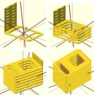
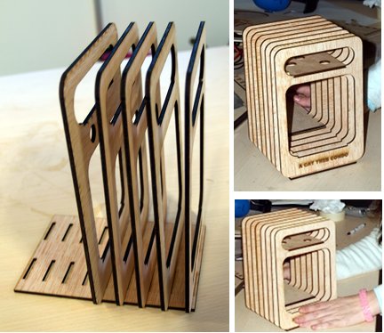
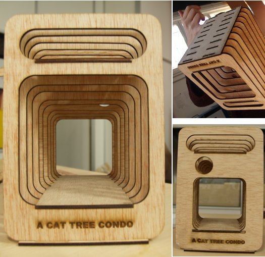
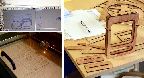
During this week I have been learning OpenScad. Here is the design I have worked on for this assignment. The module is composed by an upper space to place all electronics that would drive cat interactions, and by the main space where the the cat is going to be.
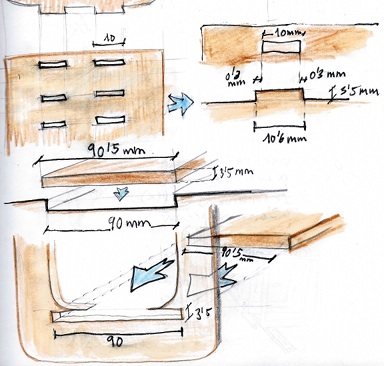
This week I have learnt that everthing that can be parametric, should. This helps one a lot during the process of designing joints, and would be handy once one wants to rebuilt it in an other material. The material I have used for this assignment is 3.5mm plywood.
From OpenScad to printing files
Once the design is done, I put every piece I wanted to cut in an OpenScad new document, in order to generate the dxf files for the Epilog. With each part of the model, that is in one document, I followed this process:
- Design - Compile and Render
- Design - Export as STL
- File - New-
- Design - Compile and Render
- Design - Export as DXF
"projection(cut=false) import ("/Users/sara/Documents/2013/Fabacademy2013/SaraPressandfit/name.stl");
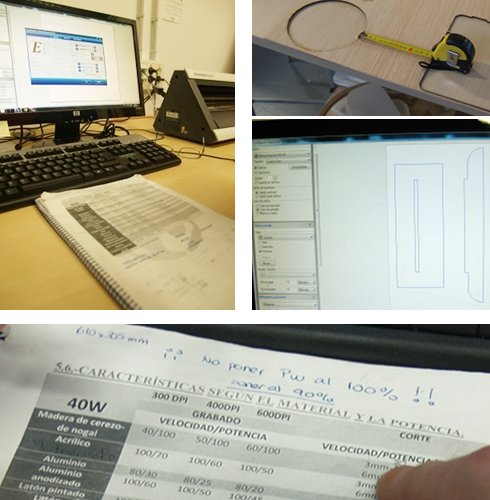
The polywood sheet and the Epilog workspace is 610mmx305mm. Once I had all dxf I laid them out trying to fit all designs in one polywood sheet to earn material and time.
Laser Cutter
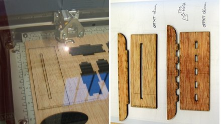
First we started doing some design to test the material and how joints worked. We used polywood remnant for this issue. The "printing window/area" on the computer should not be bigger than the rest of material we had prepared for cutting. To send the printing files to the Epilog we used the Epilog driver and its mapping colors option. We sent files from Rhino and we prepared our files like this:
- Red lines (by layer): Rastering (Speed/Power) 40/90
- Blue lines (by layer): Cutting (Speed/Power/Frequency) 20/90/500
PressAndFitResults ·····························································································