Computer Controlled Cutting
This week had two machines and two jobs. On the laser cutter I designed and built a parametric press fit construction kit, a set of flat pieces that slot into each other so I can build many shapes without any glue. On the vinyl cutter I cut, weeded and transferred a sticker. The whole point of computer controlled cutting is that I draw on the computer and the machine cuts exactly what I drew, again and again, the same every time.
What this week is about
Computer controlled cutting means a computer guides a machine to cut, engrave or shape a material with high precision instead of doing it by hand. At Node Fab Lab Rwanda we used the laser cutter on wood, acrylic and cardboard, and the vinyl cutter on sticker sheets. I designed in SolidWorks for the parametric kit and Inkscape for the sticker, and I prepared the laser jobs in LightBurn.
Group assignment and lab safety
Before designing anything serious, my group characterised the laser cutter together so we would know how it behaves on our material. We wrote up the focus method, the power and speed tests, the kerf measurement and the joint clearance results on our shared page.
Link to the group assignment page
We also did the lab safety training first, and a few things stayed with me. The laser can start a fire if it is left running alone, so someone always watches the machine while it cuts. The exhaust fan and air filter must be on so the smoke and fumes are pulled away instead of breathed in. I keep the lid closed during a cut because the beam can damage eyes, I keep flammable scraps off the bed, and I know where the stop button and the fire blanket are before I start. For the vinyl cutter the safety lesson is smaller but real: keep fingers away from the blade carriage and never reach under the machine while it is running.
Characterising the laser cutter
We ran a set of small tests so that later we could trust our numbers instead of guessing. Here is what each thing means and the real numbers we got on our machine cutting 3 mm plywood.
- Focus. The laser cuts cleanest when the lens is at the right distance above the material so the beam is at its smallest point on the surface. We set the focus with the focus gauge that came with the machine, around 6 mm of lens to material distance for our bed. Wrong focus gives a wide, weak, burnt cut that does not go through.
- Power and speed. These two work together. More power and slower speed cuts deeper and darker, less power and faster speed only marks the surface. We ran the same square at different settings and read which one cut clean through without too much burning.
- Rate. The rate, or frequency, is how many laser pulses fire per second. A higher rate gives a smoother continuous cut, a lower rate can leave a dotted edge. We left it near the maker default for plywood and only adjusted power and speed.
- Kerf. This is the most important number for joints. More on it below.
- Joint clearance and types. We cut a comb of slots at different widths and pushed a tab into each to find which one held as a press fit. We also tried a press fit slot joint and a finger joint at the corners.
| Setting | What we used (3 mm plywood) | Result |
|---|---|---|
| Focus height | about 6 mm lens to material | narrow, clean beam |
| Power (cut through) | about 70 percent | cuts fully through |
| Speed (cut through) | about 10 mm per second | clean edge, little char |
| Power (engrave) | about 20 percent | marks the surface only |
| Rate / frequency | maker default for plywood | smooth continuous cut |
| Measured kerf | about 0.2 mm | used to size every slot |
| Joint clearance | slot width = thickness minus 0.2 mm | tight press fit |
What kerf is and why it matters
Kerf is the small amount of material the laser beam burns away along the cut line. The beam has a real width, so the line it removes is not infinitely thin. On our machine and material the kerf came out around 0.2 mm, which means a cut takes away roughly 0.1 mm from each side of the line.
That sounds tiny but it is the whole story for press fit joints. If I cut a slot to exactly the material thickness, the kerf removes a little extra and the slot ends up wider than the tab, so the joint is loose and falls apart. To get a tight press fit I make the slot a touch narrower than the thickness, by the kerf amount, so that after the beam eats its share the slot ends up exactly the right size. We measured the kerf by cutting a known size and comparing it to the real cut size, then used that one number everywhere.
My parametric 2D design method
I designed the kit in SolidWorks using parameters, which means the key sizes are linked to a few numbers I control in one place instead of being typed into every shape. I made three driving values: material thickness, kerf, and slot width. The slot width is not a number I type, it is a formula.
"thickness" = 3
"kerf" = 0.2
"slot_width" = "thickness" - "kerf"
Because the slot width is set to thickness minus kerf, the slot comes out slightly narrower than the board, which is exactly what a press fit needs. The real strength of doing it this way is that the kit is reusable. If I switch to a thicker board later I change the thickness value once, and every slot in every piece updates by itself, no redrawing. If a different laser gives a different kerf, I change the kerf value once and all the joints retighten.
Making the press fit construction kit
With the parameters set, I drew a simple repeatable piece with slots on its edges so any piece can grip any other piece. I built the kit step by step and tested the joint before committing a whole sheet.
- Designed one base piece in SolidWorks with slots sized by the slot width formula.
- Exported the outline as a vector and brought it into LightBurn.
- Cut a single test joint first, just one slot and one tab, to check the real fit.
- The first try was a little loose, so I nudged the kerf value up and let the slot width formula retighten the slot.
- Cut the test joint again. This time it clicked together and held on its own with a firm push.
- Set the power and speed from our group table and cut the full set of pieces.
- Popped the pieces out of the sheet and assembled them.
Because every slot is identical, the pieces connect in many directions, so I could build flat patterns, a tall tower and a boxy shape all from the same kit, taking them apart and rebuilding without glue.
The vinyl cutter project
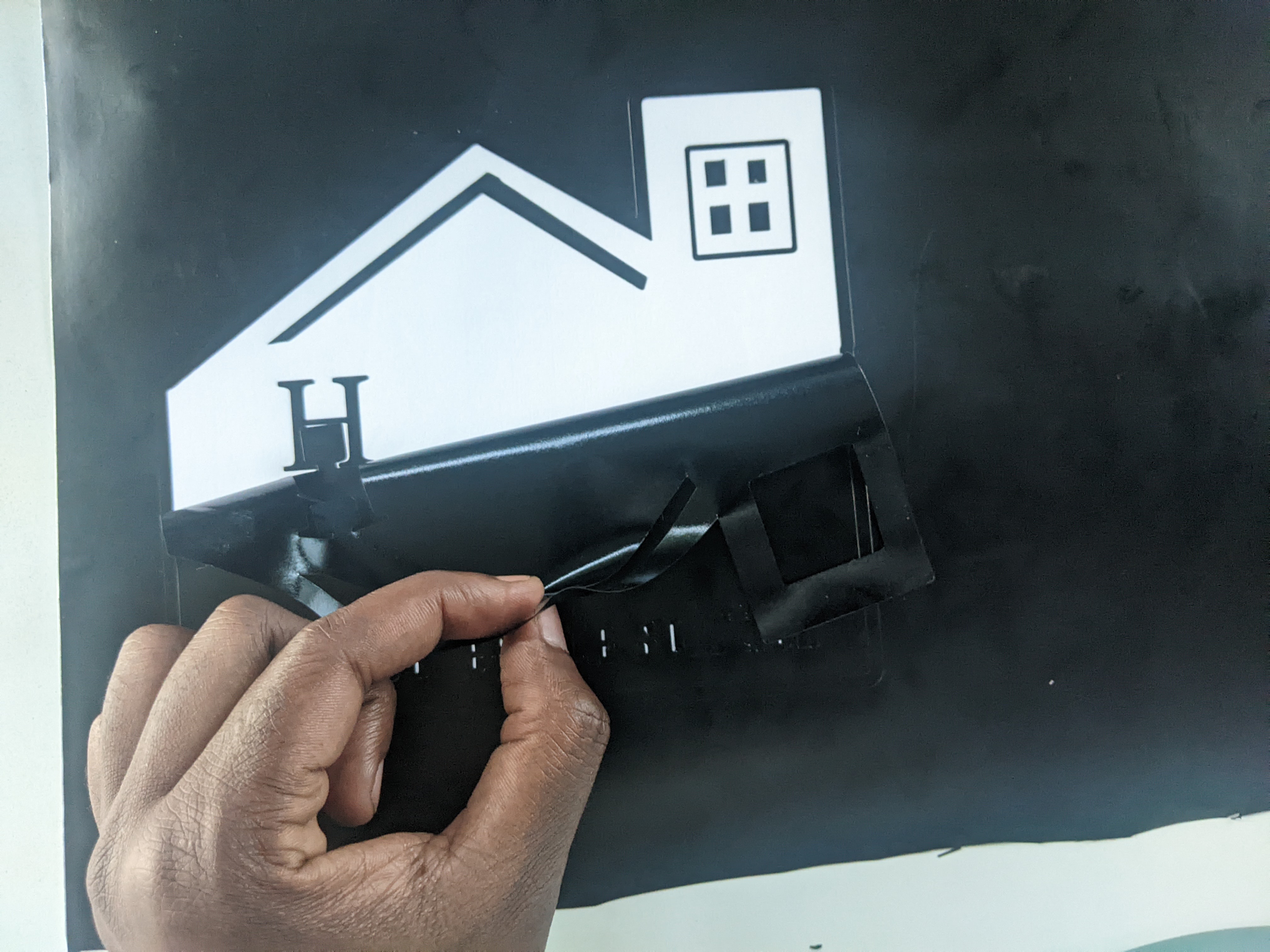
For the vinyl cutter I made a sticker of my DEI logo. The vinyl cutter drags a tiny blade along the path I drew and cuts the outline of the design without cutting through the paper backing underneath.
- Design. I prepared the DEI logo as a clean single colour vector in Inkscape, with closed paths and no stray lines, then sent it to the cutter.
- Cut. I loaded the vinyl and set a light blade pressure so the blade cut only the vinyl layer and left the backing intact.
- Weeding. Weeding means peeling away the parts of the vinyl I do not want, leaving only the logo stuck to the backing. I used a fine pick to lift the small inside pieces.
- Transfer. I laid transfer tape over the weeded logo, rubbed it down, peeled the tape up so the logo lifted off the backing in one piece, then pressed it onto my laptop and peeled the tape away, leaving the sticker behind.
Problems and how I fixed them
The first slot was loose because I had not accounted for the kerf. Once I set the slot width to thickness minus kerf and retightened it with a slightly larger kerf value, the press fit held. The vinyl tore while weeding because the blade was set too deep and had scored the backing. I lowered the blade pressure so it cut only the vinyl, and after that the weeding came away clean.
What I learned
The kerf is the whole story this week. A press fit lives or dies on a fraction of a millimetre, and writing the slot width as thickness minus kerf meant I could fix that fraction in one place instead of redrawing everything. Cutting a single test joint before the full run saved me a wasted sheet, and the safety habits from the training are now automatic before every cut.
Design files
These are the original editable files from this week so anyone can open, change the thickness or kerf, and reuse them.