Introduction
3D printing and 3D scanning are key technologies in digital fabrication that enable interaction between the digital and physical worlds. 3D printing is an additive manufacturing process in which a physical object is created from a digital 3D model by depositing material layer by layer until the final form is achieved. Designers typically create models using computer-aided design tools such as Fusion 360 or Tinkercad, then prepare them for printing using slicing software like Ultimaker Cura or Creality Print, which converts the model into machine instructions that guide the printer during fabrication. In contrast, 3D scanning is the process of capturing the geometry of a real-world object and converting it into a digital 3D model. This can be done using scanning devices or photogrammetry tools such as Polycam or Meshroom, which reconstruct a three-dimensional model from multiple images taken from different angles
Assignments
Group Assignment
As a group we tested and documented the design rules of our 3D printers, printing test parts to measure the real limits for overhangs, bridging, wall thickness, and clearance. You can view our group assignment
Here is what I learned from testing each design rule on our Creality K1 with PLA, written from my own observations on the test prints:
- Overhang. I printed a fan of walls leaning out at growing angles. Up to about 45 degrees from vertical the surface stayed clean. Past 50 degrees the underside started to droop and the filament curled because each new layer had too little of the layer below to rest on. So 45 degrees is my safe overhang limit before I need support.
- Bridging. I printed flat gaps spanned with no support underneath. Short bridges of around 5 to 10 mm came out almost flat because the plastic cooled fast enough to hold. Once the gap passed roughly 20 mm the middle sagged and the strands drooped. Good part cooling and slower bridge speed made the long bridges much better.
- Wall thickness. Our nozzle is 0.4 mm. Walls thinner than the nozzle simply did not print as solid plastic, they came out as gaps or single weak lines. A wall of about 0.8 mm, which is two perimeters, was the thinnest that printed strong and reliable.
- Clearance. I printed two parts side by side with different gaps between them to see when they fuse and when they move freely. A gap of 0.1 mm fused into one solid block. A gap of about 0.3 to 0.4 mm let the parts move freely while still staying captive. This clearance test is exactly what told me what gap to leave inside my pre assembled piston.
Individual Assignment
The individual assignments consisted of two activities: first, designing, documenting, and 3D printing a small object that cannot be produced using subtractive manufacturing, typically involving complex geometries or moving parts that benefit from additive fabrication; and second, 3D scanning a real object to generate a digital 3D model, which could optionally be cleaned, modified, or reproduced through 3D printing.
These tasks provided practical experience in both creating objects through additive manufacturing and digitizing real-world objects for further design and fabrication.I came to know that cerain angle doesn't need support.
Tools & Software Used
I used a combination of tools and software to complete the project. The 3D model was designed using SOLIDWORKS, where sketches, extrusions, fillets, and chamfers were applied to create the final part. The model was then prepared for printing using the slicer software Creality Print, which allowed adjustment of parameters such as infill, layer height, speed, and supports, and exported the G-code for the printer. The object was fabricated on the Creality K1 3D Printer, building the design layer by layer. Optionally, 3D scanning software like Polycam or Meshroom can be used to capture real-world objects and generate digital models for printing.
| SOFTWARES AND TOOLS | Purpose | Notes |
|---|---|---|
| SOLIDWORKS | CAD Softwares used to design 3D | There are other softwares like Fusion ,openshape , thinkercad etc |
| Creality Print | Slicer software that edit and process printing parameters of a designed 3d with specific printer | recent creality known slicer |
| 3D printer Ender v3 K1 | 3D Printing | |
| Filament | PLA filament being melted to form our shape | There are other types of filaments such as PETG ,esun , silicon ... |
| Cutter | cut filament at 45 degrees |
Step-by-Step Process
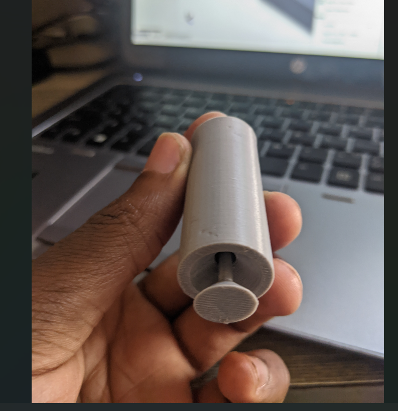
For my individual assignment I designed a small piston mechanism, a piston sitting inside a cylinder that already moves the moment the print finishes. I printed it as one job with the two parts already nested together, leaving the clearance gap I had found in the group clearance test so they stay captive but slide freely.
Why this could not be made subtractively. Subtractive methods like milling or turning have to reach the material with a tool. My piston is trapped inside the cylinder and the moving gap between them is fully enclosed, so there is no path for a cutting tool to reach in and carve that gap once the parts are together. To make it subtractively I would have to machine the piston and the cylinder as two separate pieces and then assemble them by hand. Printing builds it layer by layer from the inside out, so it comes off the bed already assembled with the internal geometry intact. That captive, pre assembled, enclosed clearance is exactly what additive can do and subtractive cannot.
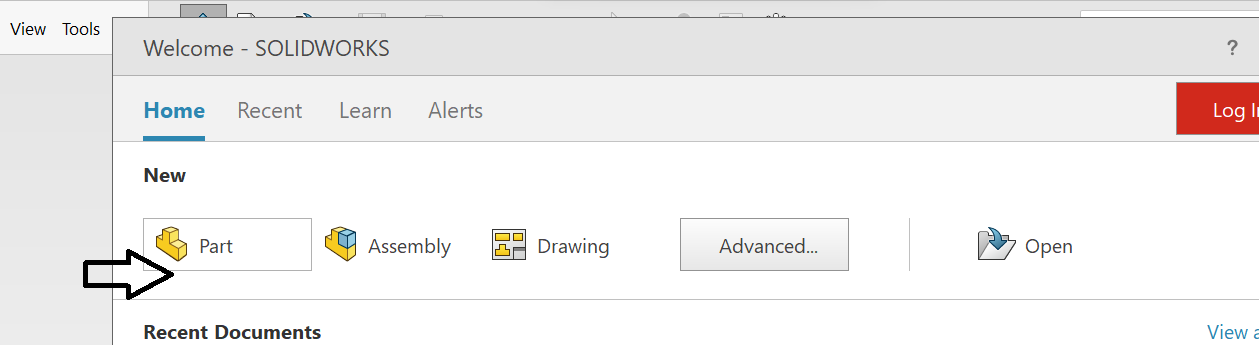
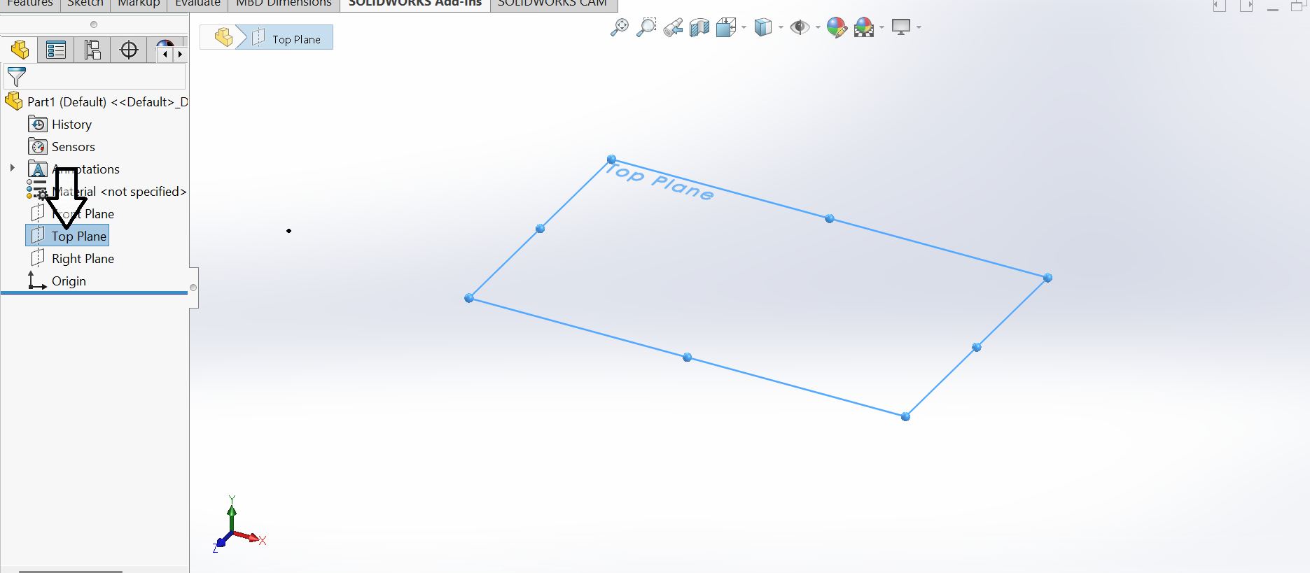
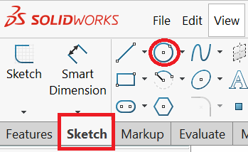
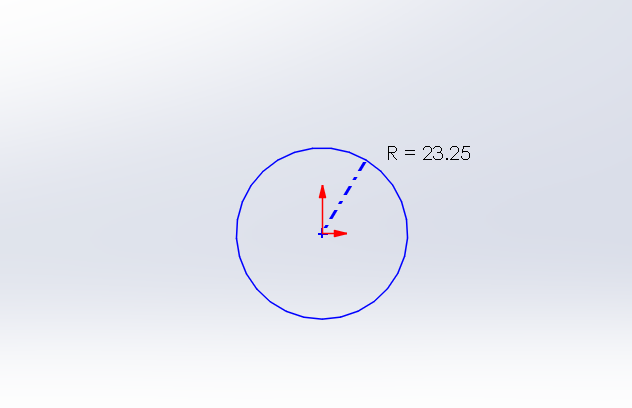
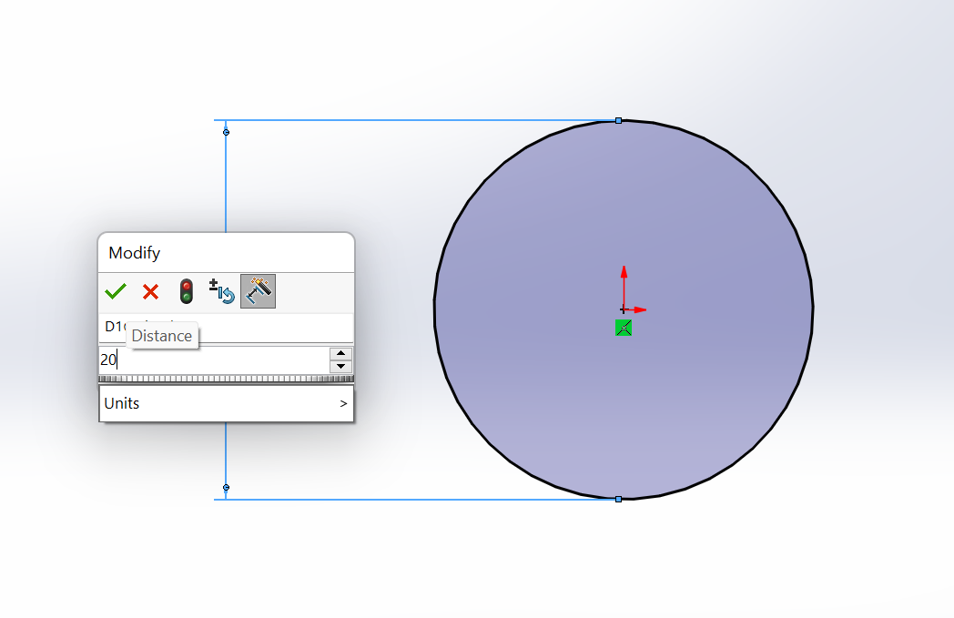
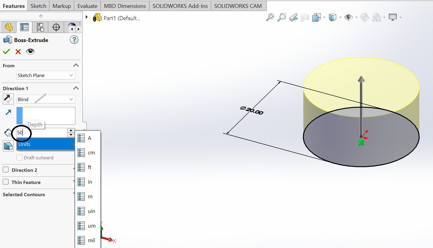
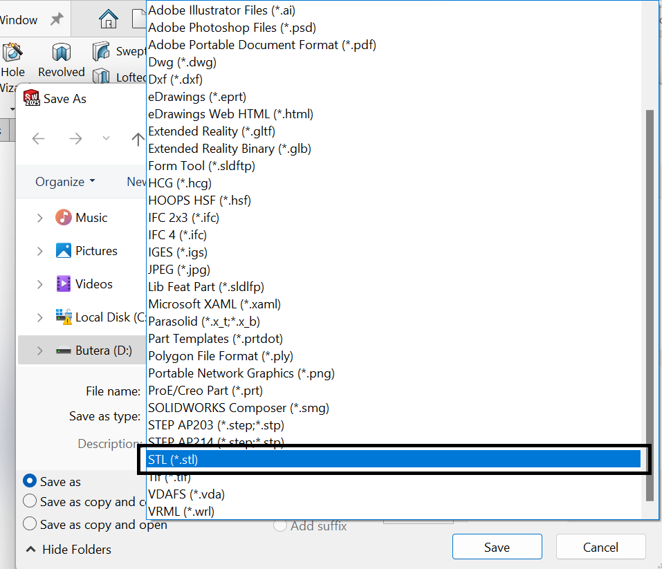
  Files exported:
  ├── Piston.SLDPRT     (SolidWorks part)
  ├── pip.STL           (mesh for slicing)

Creality print
3D scanning a real object
The second part of the week was to scan a real object and turn it into a digital model. I used the Sense 3D scanner in the lab. I placed my object on a table, started the scanner, and walked slowly around it so the camera could see every side. The scanner builds the shape live on the screen as you move, so I could see which spots were still missing and go back over them. After the scan I cleaned up the mesh, closed a few small holes, and saved it so it could be reprinted if I wanted.
Here is what I found scans well and badly with the Sense. Matte, light coloured surfaces with plenty of texture and rounded shape scan well, because the camera has features to lock onto. What scans badly is shiny and very dark surfaces, the camera cannot read the reflection so it leaves holes, and thin edges or deep narrow pockets get lost because the camera never sees fully inside them. Moving smoothly and holding a steady distance also matters a lot, if I moved too fast the scanner lost tracking and I had to start that side again.
My step by step on the Sense scanner: place the object on a clear table, start the scan, slowly circle the object keeping it framed and at the same distance, watch the live mesh and go back over any grey missing spots, finish the scan, then clean the mesh by closing small holes and trimming the leftover table, and finally save it so it can be reprinted.


Conclusion
3D printing and 3D scanning are powerful digital fabrication technologies that connect the digital design world with physical manufacturing. Through this assignment in Fab Academy, I learned how to design objects using CAD software like SOLIDWORKS, prepare them for fabrication using slicing tools such as Creality Print, and produce them using a 3D printer. The process also highlighted the importance of design rules, including limits for overhangs, clearances, and wall thickness, to ensure successful prints. In addition, 3D scanning demonstrated how real-world objects can be captured and converted into digital models for analysis, modification, or reproduction. Overall, this experience showed how additive manufacturing enables the creation of complex geometries, internal structures, and pre-assembled mechanisms that would be difficult or impossible to produce with traditional manufacturing methods
Original Design Files
Here are my original 3D printing files for the piston so anyone can open the part, edit it, or reprint it.