Electronics Design
Week 6 — Group Assignment
This week, we used Fab Lab Rwanda’s test equipment—oscilloscope, function generator, multimeter, and power supply—to observe and analyze signals from a microcontroller circuit. We programmed an ESP32 and measured its digital and analog signals using these tools. The hands-on experience helped us understand how oscilloscopes, waveform generators, and multimeters work together for electronics testing and troubleshooting.
Oscilloscope
An oscilloscope displays electrical signals as waveforms, showing how voltage changes over time. It allows you to visualize and analyze the shape, amplitude, frequency, and other characteristics of signals.
- Viewing digital and analog signals
- Measuring signal frequency and amplitude
- Analyzing signal integrity
- Debugging electronic circuits
Waveform Generator
A waveform generator (function generator or signal generator) produces different types of electrical waveforms over a wide range of frequencies. It is used for testing and troubleshooting circuits by providing controlled input signals.
- Generating sine, square, triangle, and pulse waveforms
- Testing circuit responses to different inputs
- Simulating various signal conditions
- Providing clock signals for digital circuits
Multimeter
A multimeter measures voltage, current, and resistance. It is a versatile tool for basic electrical measurements, continuity checks, and troubleshooting.
Power Supply
A power supply provides a stable and controlled source of electrical power, converting AC from the wall outlet to DC needed by electronic circuits.
Digital Signal from ESP32
We observed the digital output from an ESP32 microcontroller on the oscilloscope. The clean square wave signals confirmed the circuit’s operation and timing.
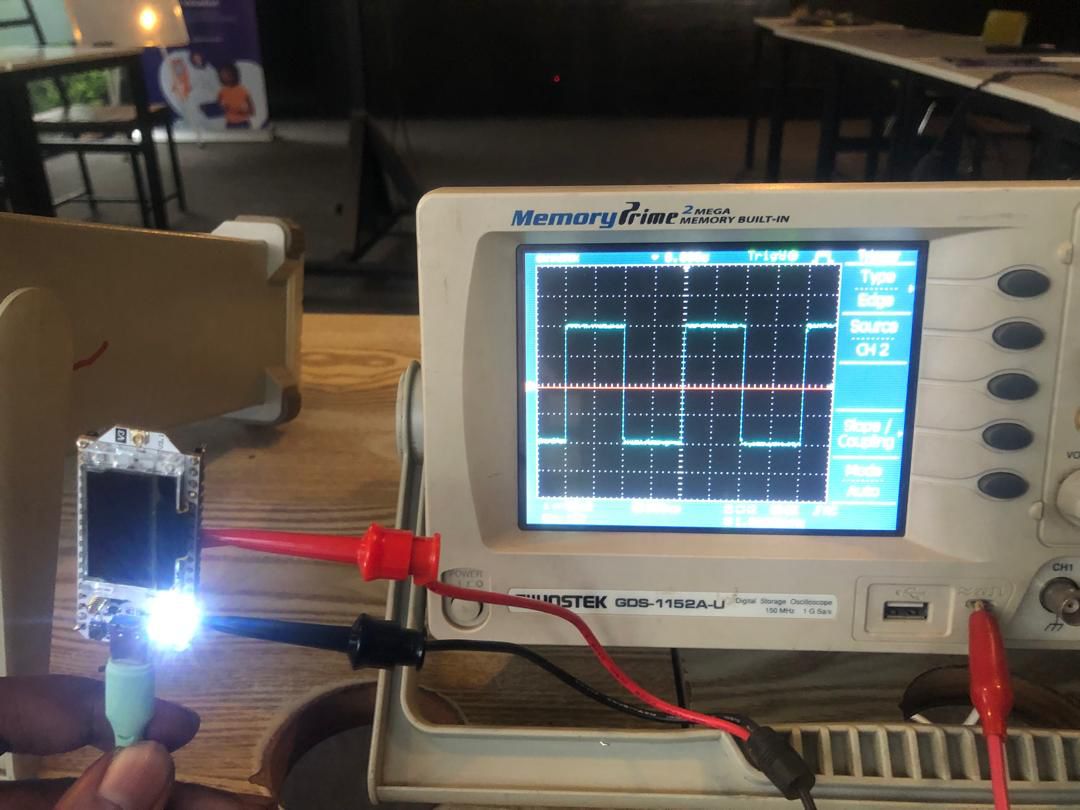
Testing digital signal from ESP32 on oscilloscope
Function Generator — Amplitude Modulation
We configured the function generator to produce amplitude-modulated (AM) signals. This allowed us to simulate modulated signals and observe how they appear on the oscilloscope.
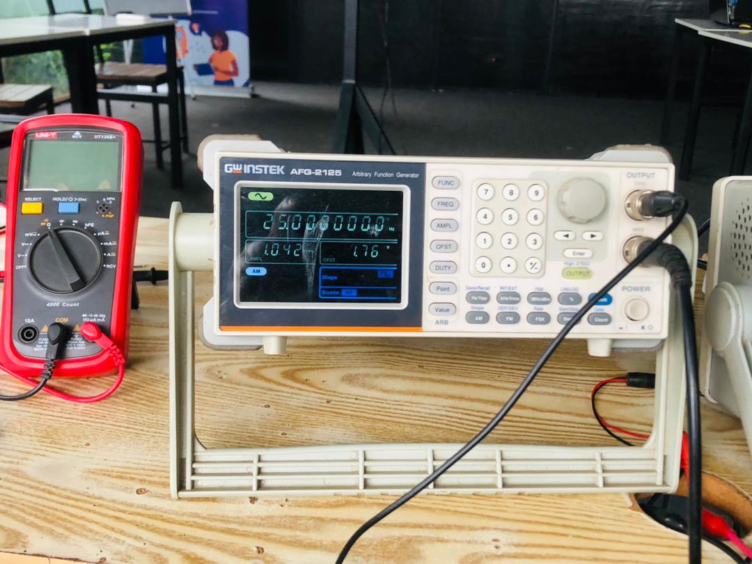
Setting amplitude modulation on the function generator
Visualizing AM Signal on Oscilloscope
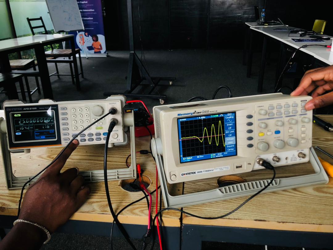
The AM signal from the function generator was displayed on the oscilloscope, showing the modulated envelope and carrier waveform.

Visualizing the AM signal from the function generator on the oscilloscope
Analog and Sawtooth Signals
We also generated and observed analog signals, including a sawtooth waveform, to compare different waveform types and their behavior on the oscilloscope.
Analog signal displayed on oscilloscope
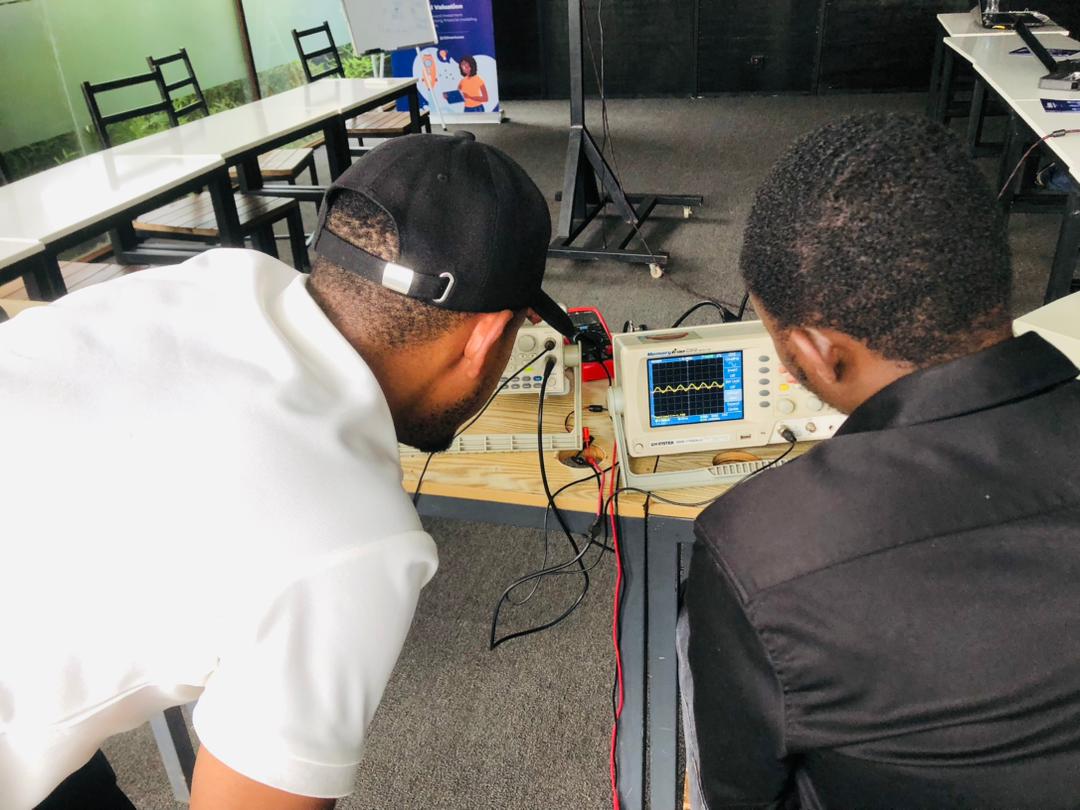
Sawtooth signal from function generator
Through our testing process, we observed:
- The oscilloscope displayed clean digital signals from the ESP32, confirming correct circuit operation.
- The function generator produced sine, square, triangle, and AM signals that we could visualize and analyze.
- Using multiple test instruments together (oscilloscope, function generator, multimeter) gave a comprehensive view of our circuit’s behavior.
- Understanding amplitude modulation and different waveform types on the oscilloscope helped us interpret signals in real circuits.
Learning Outcomes
This hands-on experience with test equipment provided valuable insights into electronics testing and troubleshooting. We gained practical experience in:
- Setting up and using the oscilloscope and function generator
- Reading and interpreting waveforms and measurement results
- Observing digital and analog signals from a microcontroller
- Documenting findings effectively as a group