
Machine Week: Hybrid Laser Cutter & 3D Printer
A collaborative digital fabrication machine engineered at FabLab Rwanda combining subtractive laser profiling, precision coordinate drawing, and additive Fused Deposition Modeling.

1. Team Organization & Task Allocation
To fulfill the Fab Academy requirement for objective team distribution, our team split development cross-functionally based on core specialties, ensuring every student owned distinct machine segments while coordinating closely for assembly and integration:
| Member Name | Core Focus Area | Specific Machine Contributions (Individual Assignment Tasks) | Portfolio Path |
|---|---|---|---|
| Manzi Muco | Mechanical Design & CAD Assembly | Chassis structural layout planning, SolidWorks modeling of V-Slot frames, eccentric spacer configurations, and gantry rail alignment logic. | View Portfolio |
| Fabiola Ingabire | Electronics, Automation & Firmware | Power distribution network wiring, high-power microstepping driver tuning, Marlin 2.0 configuration parameters, endstop logic routing, and hardware pull-downs. | View Portfolio |
| Dei Francoise | Diagnostics & Coordinate Calibration | Web Serial G-code interface staging, coordinate transformation tracking, E-step configuration testing, and mechanical limit calibration checks. | View Portfolio |
2. Core Machine Concept & Initial Sketches
The project started with a clear objective: design a modular, robust Cartesian framework capable of switching between sub-millimeter printing heads and laser diode profiles. Before opening any digital drafting tools, the system coordinates, pulleys, linear paths, and limit points were planned on paper.
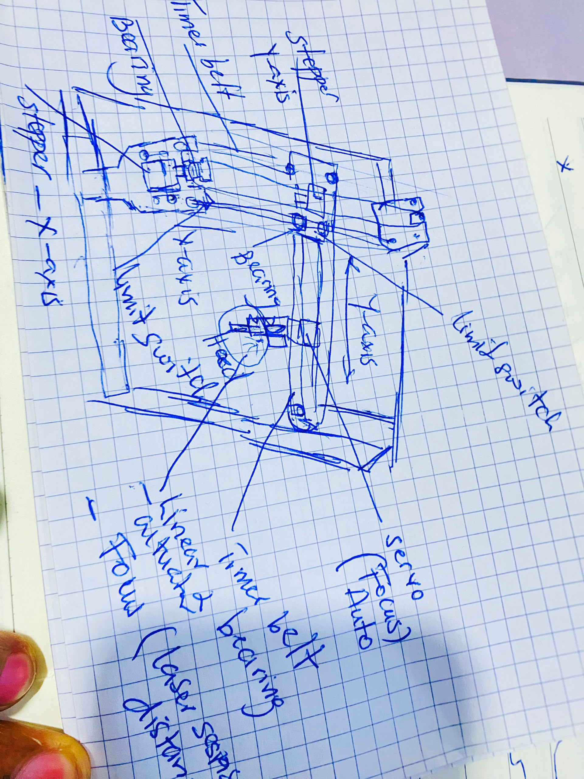
Proposed Machine Features: A rigid gantry driven by industrial microstepper pulses, absolute coordinate registration through localized tactile endstops, and a dedicated low-power electronics cabinet safely distributing high voltage separate from microcontrollers.
3. SolidWorks Mechanical CAD, Assembly & Simulation
Using the dimensions derived from the paper prototypes, the system components were modeled inside SolidWorks. 2020 and 2040 industrial aluminum rail profiles were utilized to maximize structural rigidity during high-acceleration tool tracking paths.
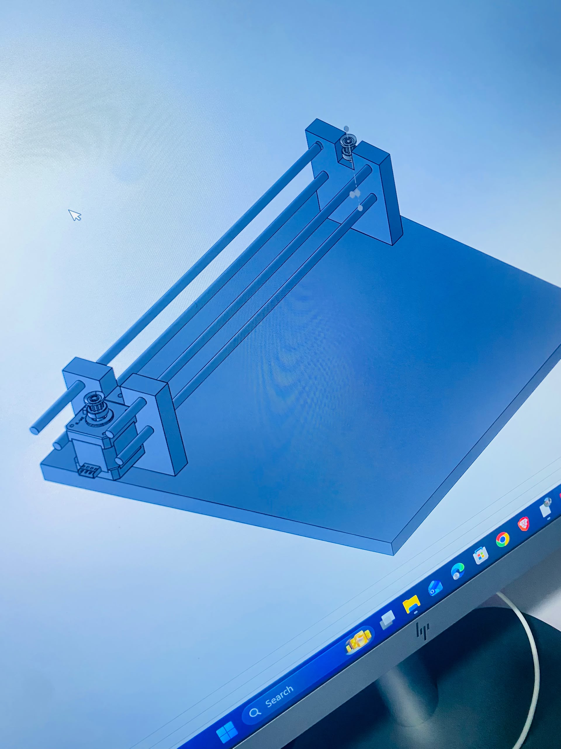
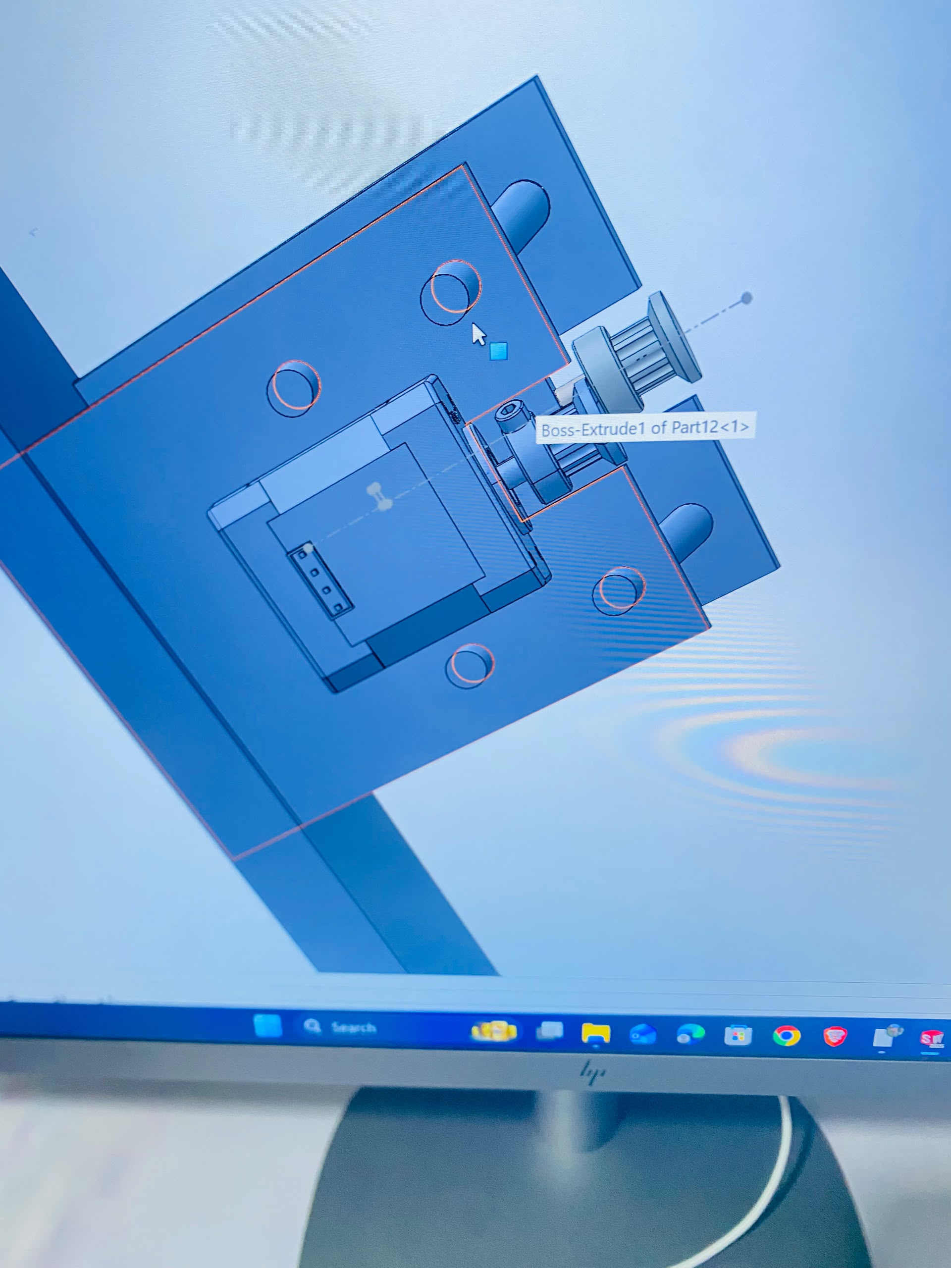
To ensure structural integrity under the mechanical load of the moving laser diode module, an engineering motion simulation was run to trace multi-axis load balances and verify tracking stability.
4. Electronics Architecture, Driver Configuration & Electrical Testing
The electronics subsystem forms the central nervous system of our machine. It requires precise configuration to protect delicate logical chips from high-current motor inductive loads.
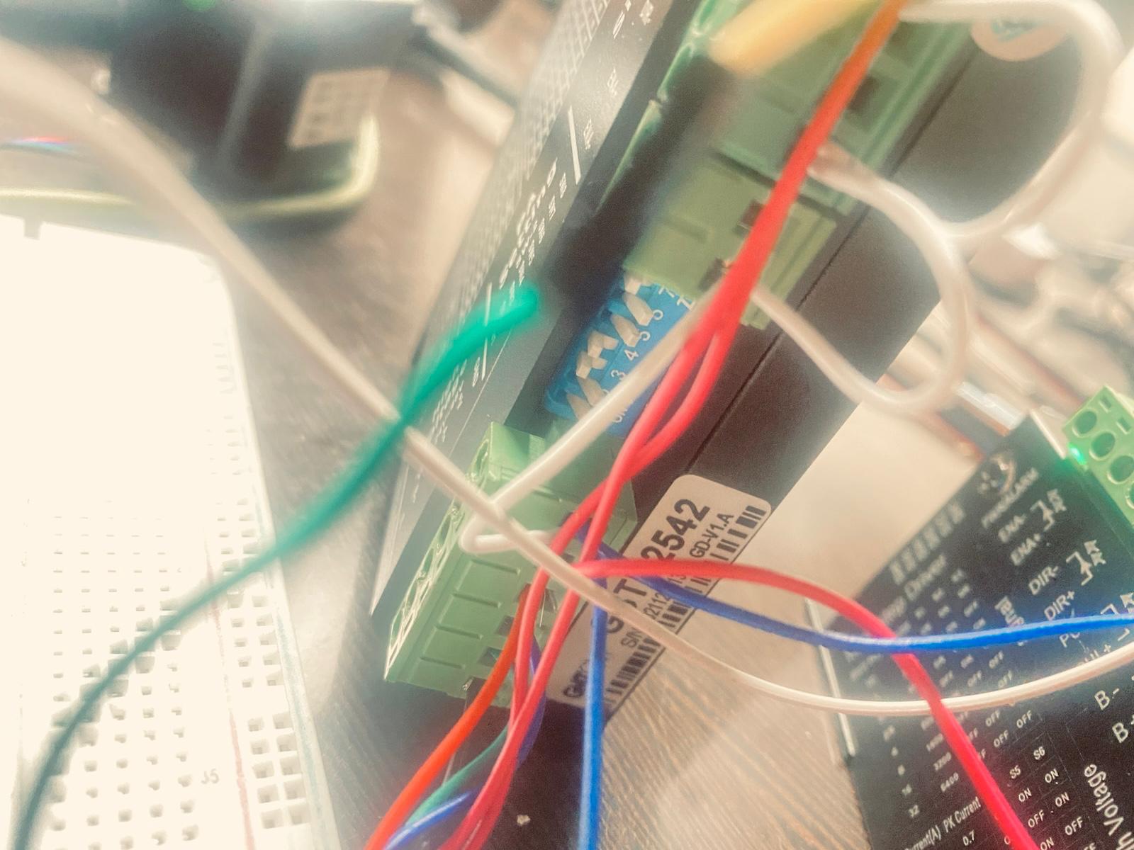
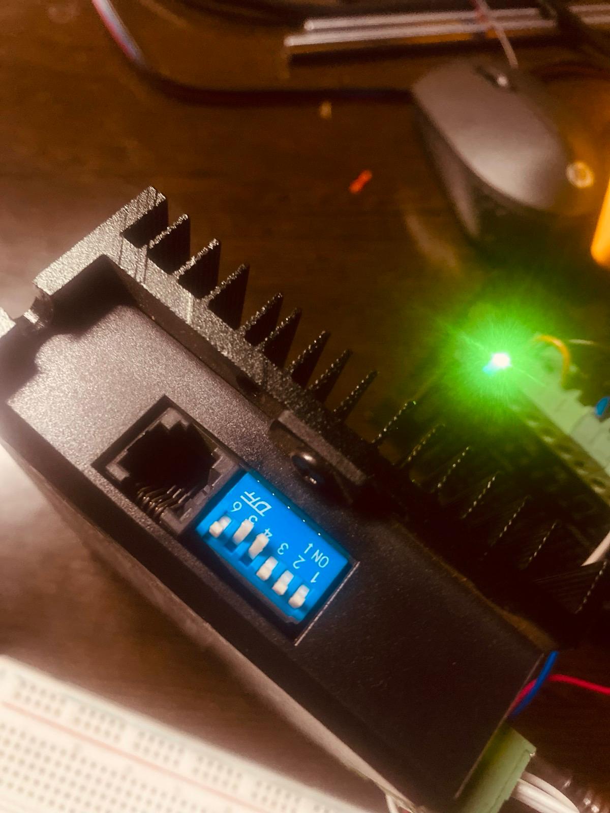
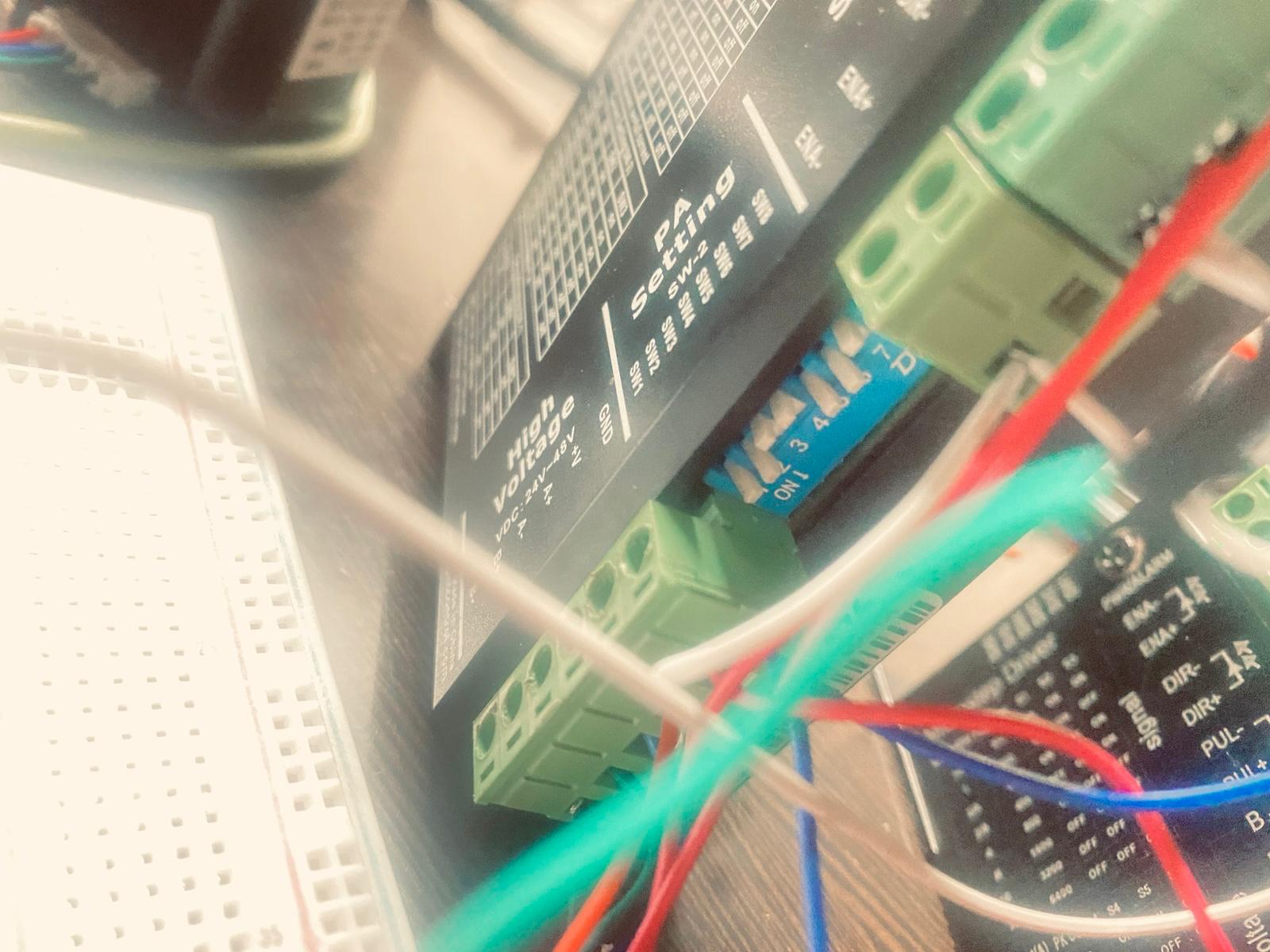
To safely manage the power curves of the heavy NEMA motors, an industrial-grade GMTCNT GSTD2542 stepper driver was configured. The onboarding DIP switches were micro-adjusted to align the step divisions and output current metrics cleanly with the microcontroller configuration variables.
5. Final Assembly Integration & Functional Validation
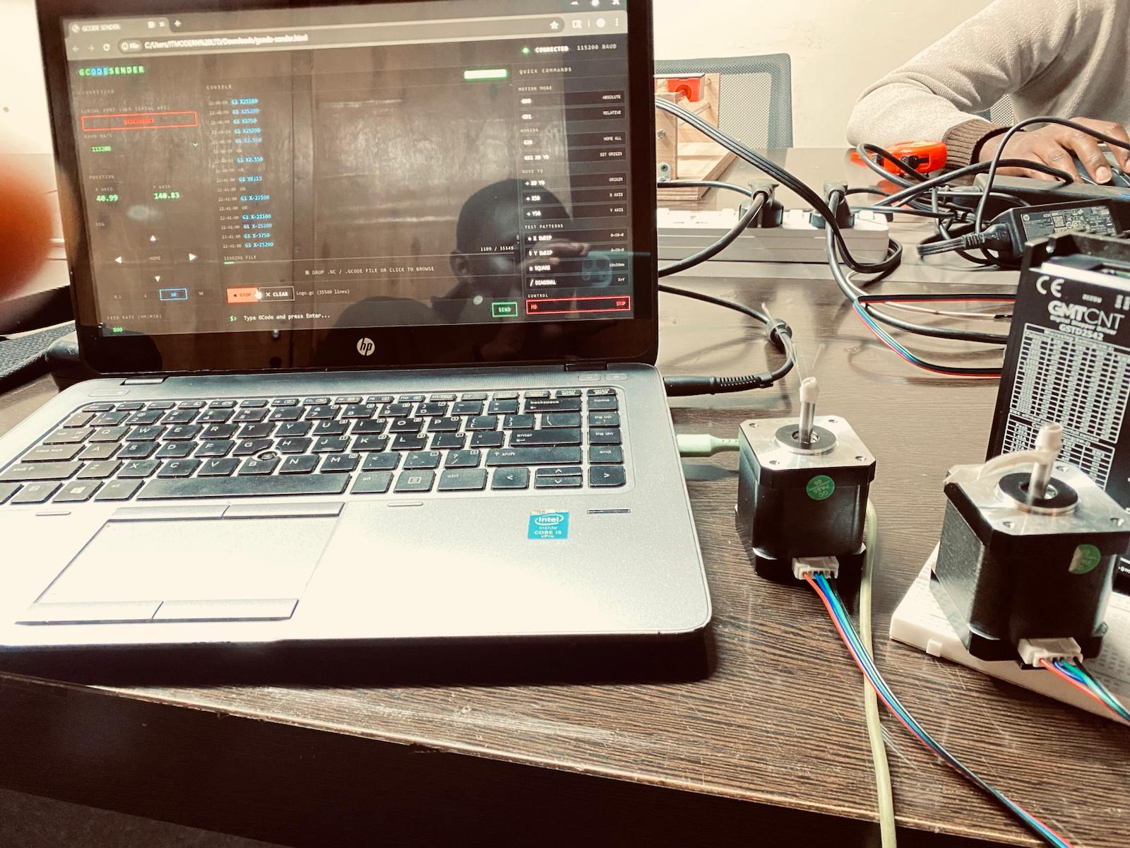
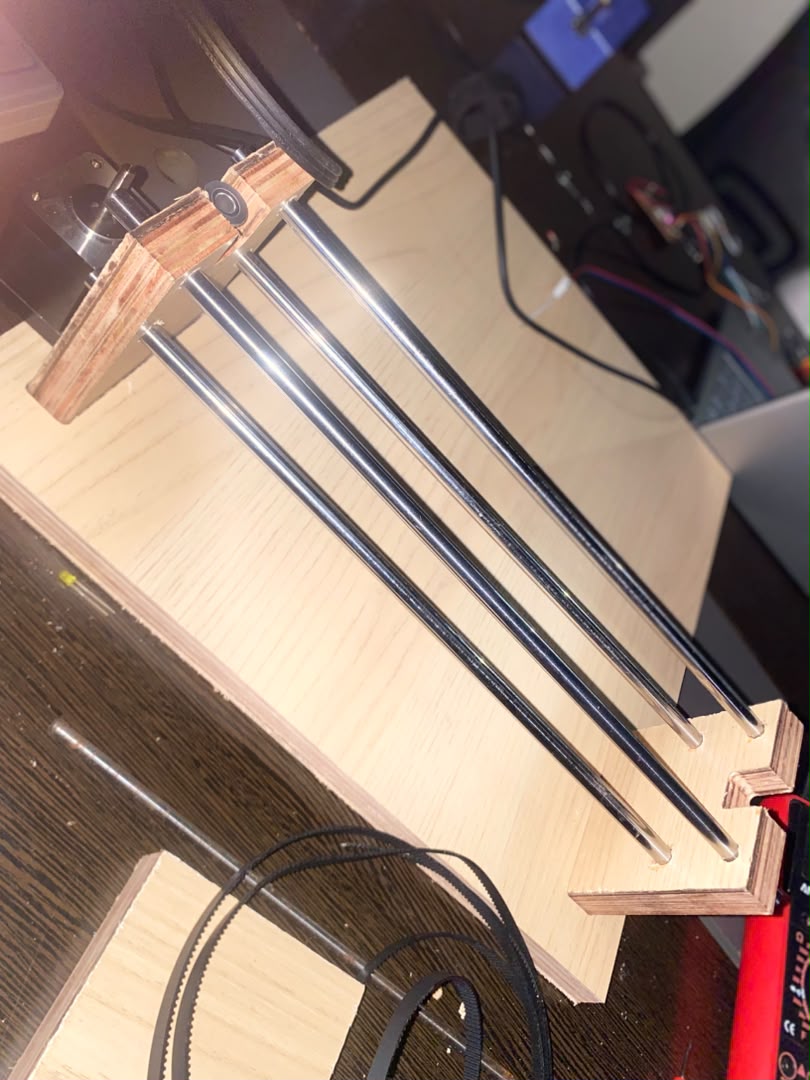
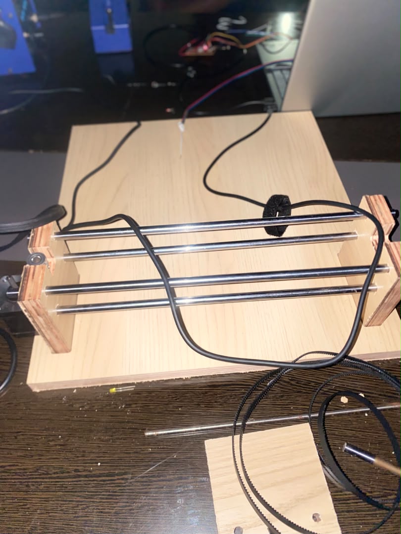
After verifying the individual mechanical axes and electronics blocks, the subsystems were integrated into the completed machine frame inside the lab workspace.
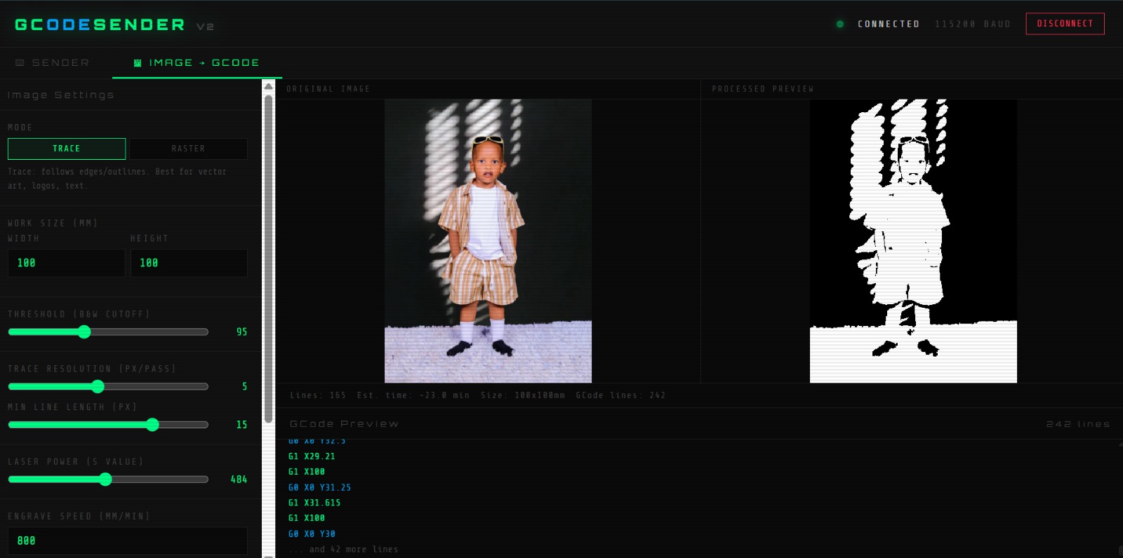
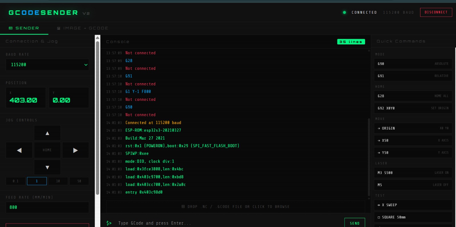
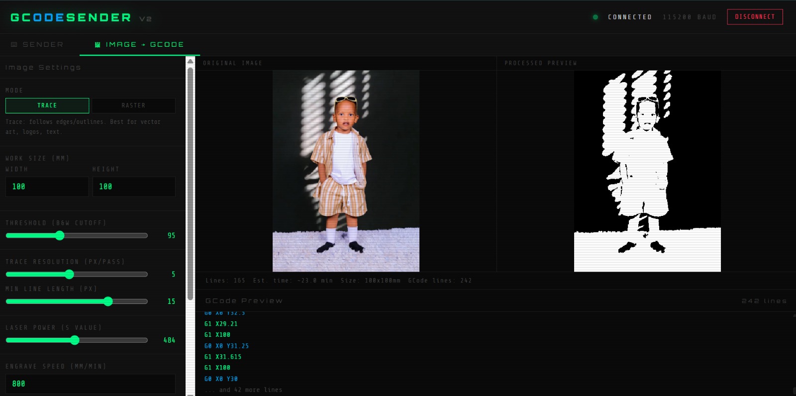
A web-based user control dashboard utilizing the Web Serial protocol at 115200 baud was deployed to transmit processing instructions and track execution points in real-time.
Subsystem Automation Performance Videos:
6. Technical Challenges & Collaborative Problem Solving
Building across different engineering disciplines revealed unique integration challenges that the team resolved through collaborative diagnostics:
| Identified Technical Bug | System Root Cause | Collaborative Engineering Fix |
|---|---|---|
| Coordinate Translation Inaccuracies | Calculated firmware steps did not match real physical dimensions due to minor structural belt slack. | Manzi tightened structural belt constraints, while Dei fine-tuned firmware calibration variables (E-steps). |
| Erratic Endstop Trip Conditions | High inductive electromagnetic radiation from motor cables leaked into endstop inputs. | Fabiola isolated wiring channels and deployed internal pull-up logic alongside software debouncing. |
| Unsafe Laser Boot-Up Spikes | The microcontroller PWM control line floated loosely during system initialization phases. | Fabiola deployed a permanent external 10 kΩ hardware pull-down safety circuit to GND. |
7. Opportunities for Future Improvements
- Automated Tool Changer (ATC): Upgrading the machine tool plate structure to collect or drop tool heads autonomously via custom G-code macros.
- Active Charcoal Exhaust Filtration: Developing an enclosed chamber layer with active extraction fans to catch volatile particulate emissions produced when cutting plastics or organic materials.
8. Master Project Repositories & Design Files
All open-source fabrication source structures, schematics, and compiled software scripts are organized in the downloads table below:
| Resource Block Type | Resource File Content Description | Source Link Access |
|---|---|---|
| Mechanical Models | Complete Machine Chassis SolidWorks Assembly, Part Models & STL Files | Download Mechanical CAD ZIP |
| Electronics & Control | Marlin 2.0 Automation Parameters & Custom Web Serial Script Packages | Download Configuration Code Package |
| Presentation Assets | High-Resolution 1920x1080 Official Project Summary Slide (PNG) | Download Summary Slide Image |