Computer Aided Design
CAD means designing on a computer before making anything. This week I tried four tools, one for each kind of design: painting a picture, turning an image into a clean vector, drawing for a laser cutter, and building a real part in 3D.
Painting in MS Paint
A raster image is made of pixels, like a photo. Paint is the simplest raster tool, so I used it to draw a scene I had in my head, a waterfall running between two mountains. I built it up brush by brush.
- Started with the water brush to lay down the base of the water.
- Switched to a small white brush to add texture on the water.
- Used a black brush to shape the first dark mountain side.
- Added the second mountain side with the same black brush.
- Brought in a green oil brush for grass texture on the mountains.
- Extended the green texture across to the other mountain.
- Added plants and made the waterfall longer to fill the empty space.
- Refined and polished the final details.
- Added the word blend to finish the artwork.
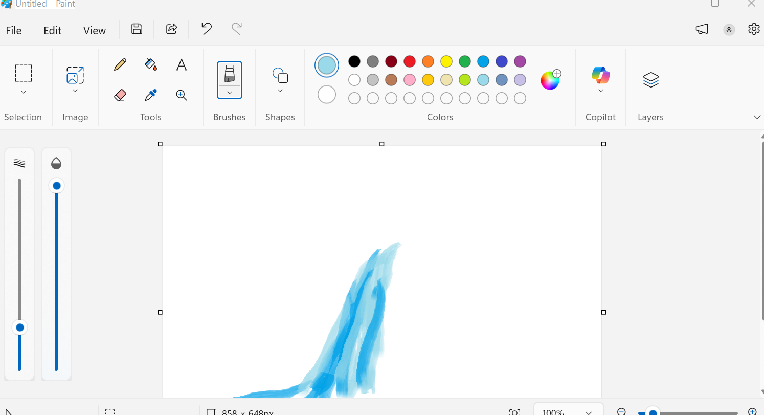
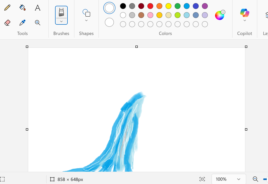
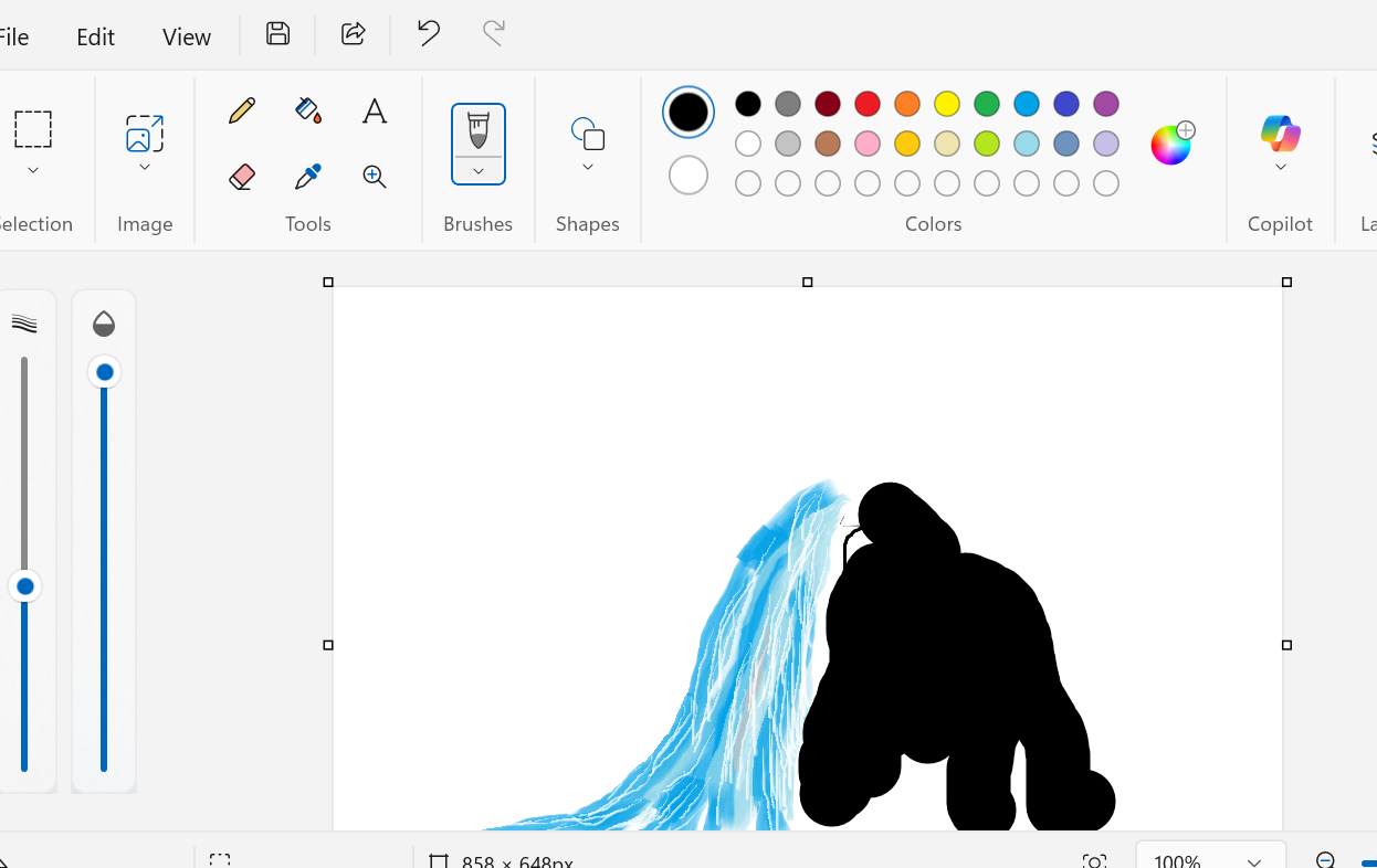
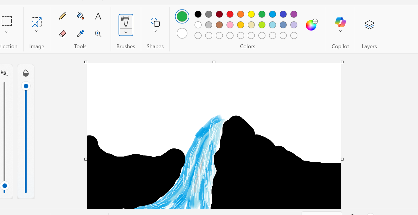
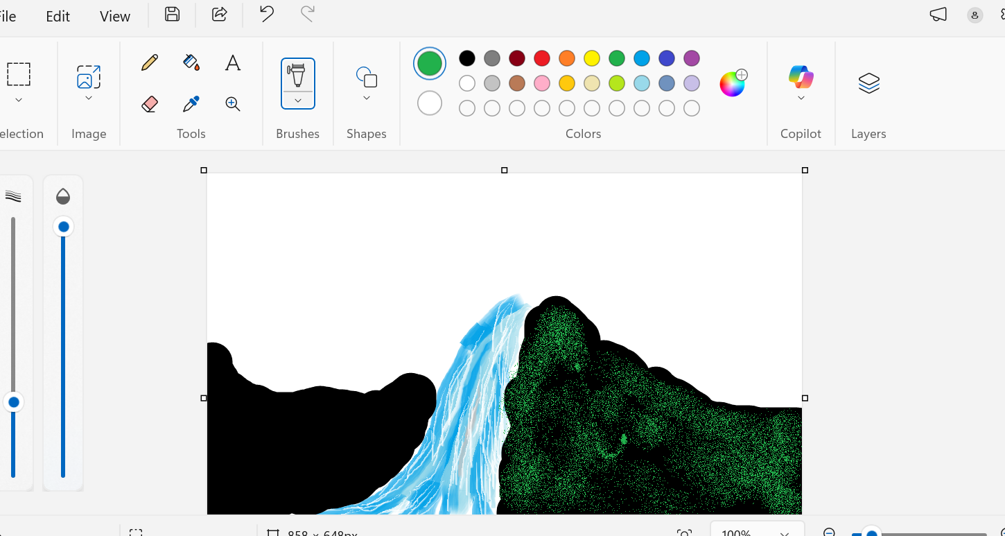
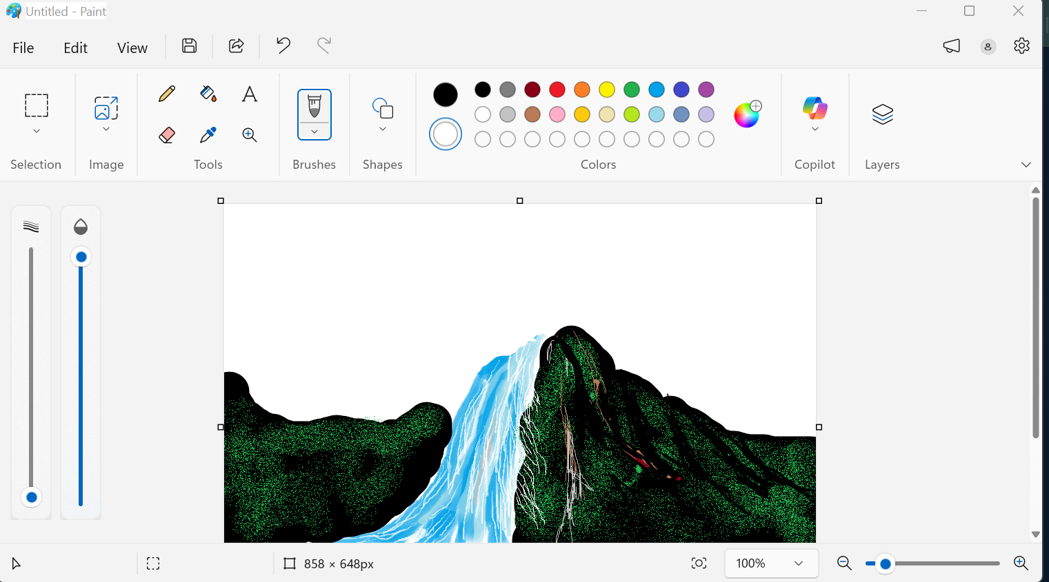
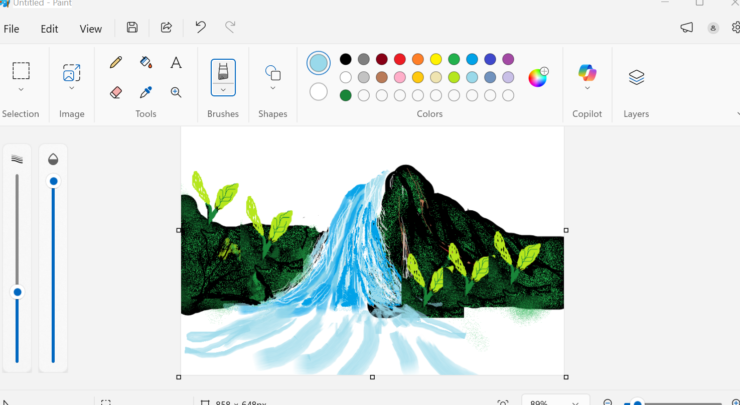
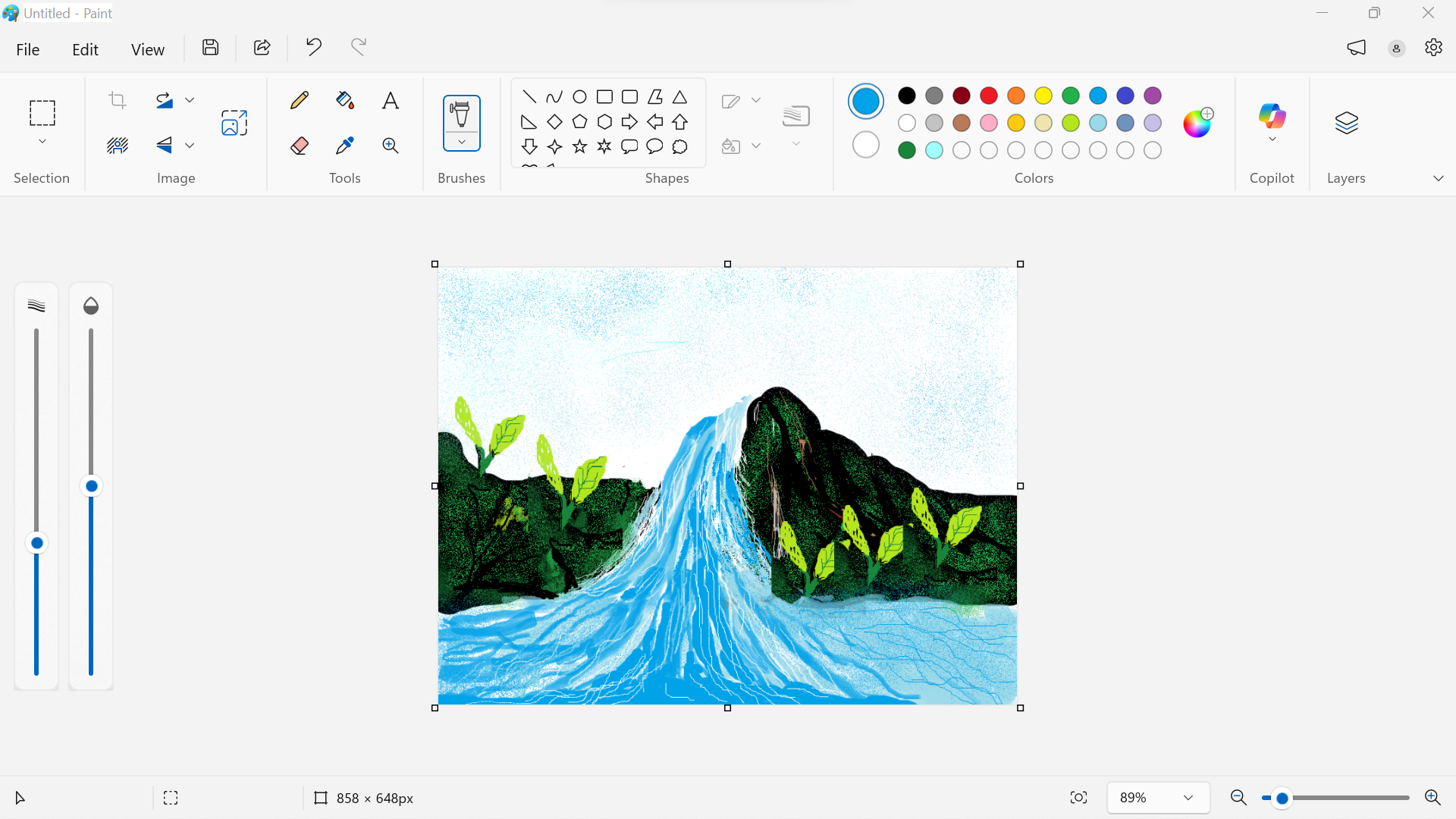
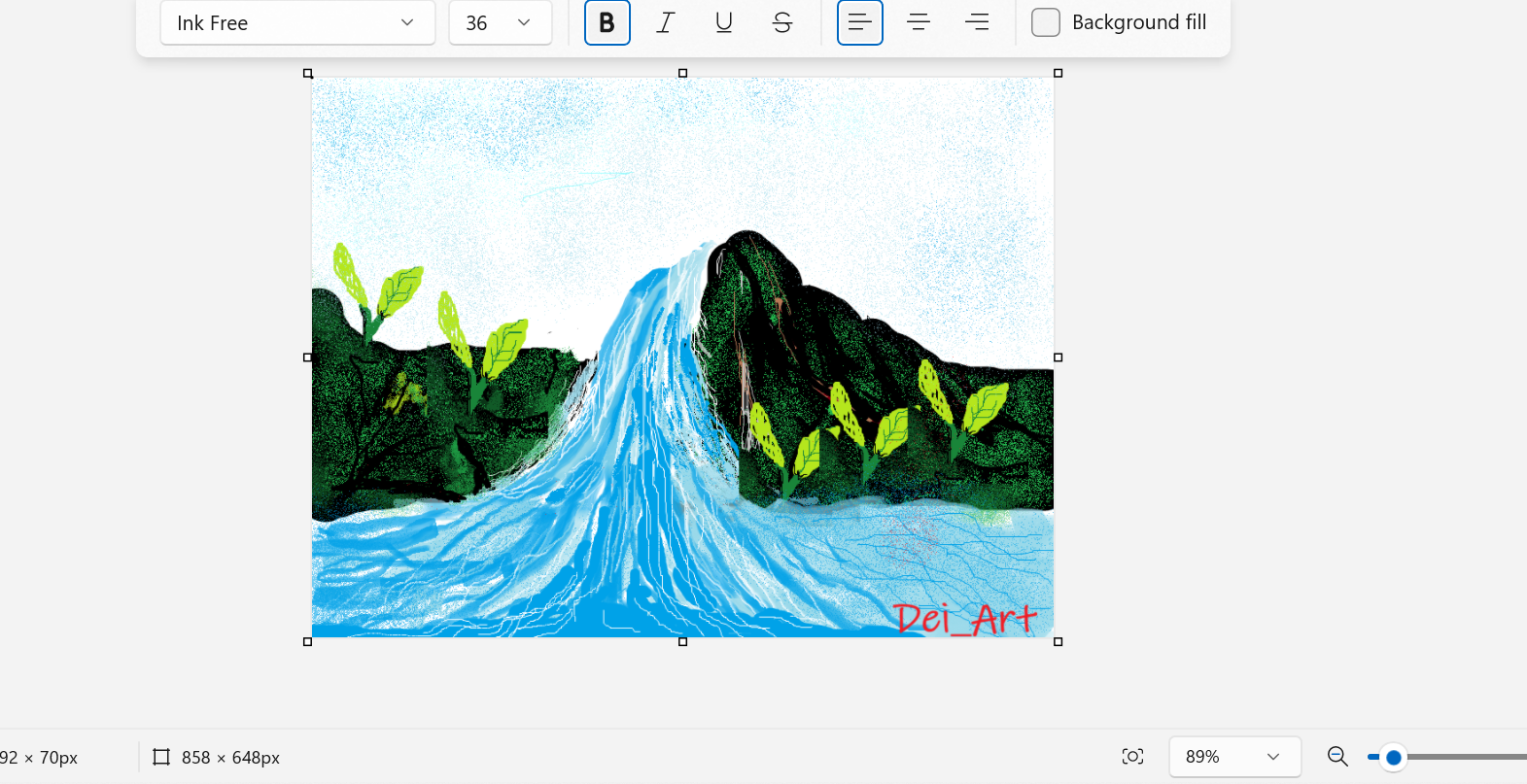
What I learned: raster painting is quick and expressive, but if I zoom in the pixels show. That limit is exactly why the next tool exists.
Tracing a vector in Inkscape
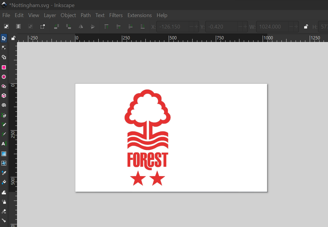
A vector image is made of lines and curves described by math, so it stays sharp at any size. I took a raster logo and turned it into a clean vector. I used the Nottingham Forest logo as my practice image.
- Downloaded the logo as a normal raster image.
- Imported it into Inkscape.
- Opened the Path menu and chose Trace Bitmap.
- Inkscape rebuilt the shape as a vector that I could scale without losing quality.

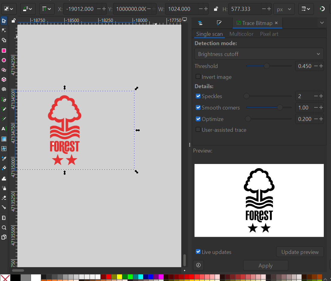
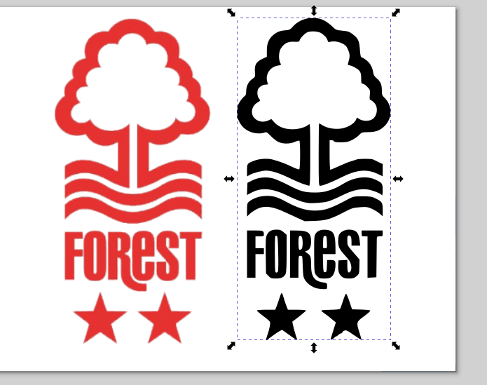
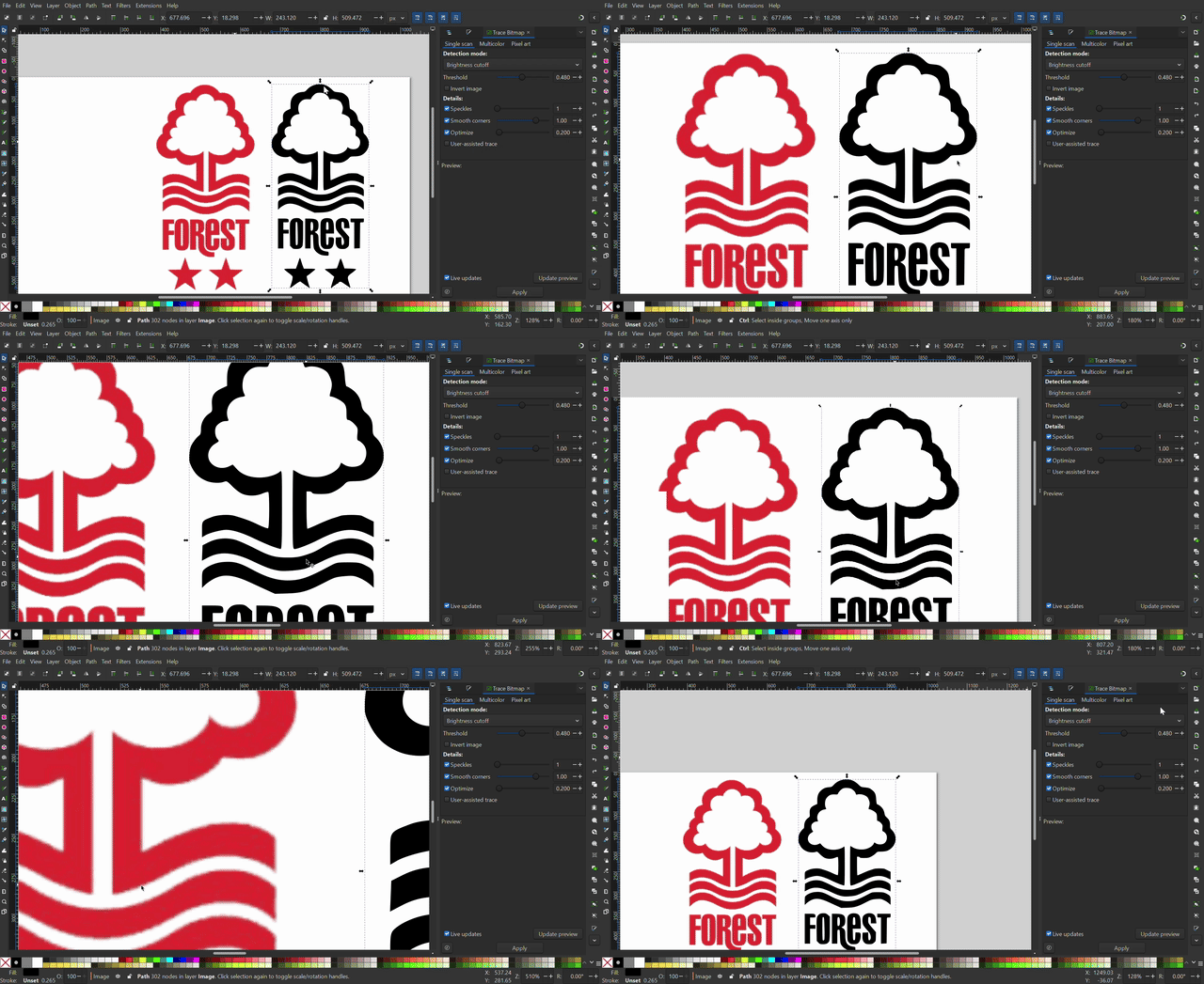
The clip above loops as a GIF, zooming in on both versions side by side so you can see the raster going blurry while the vector stays crisp.
Drawing for the laser in LightBurn
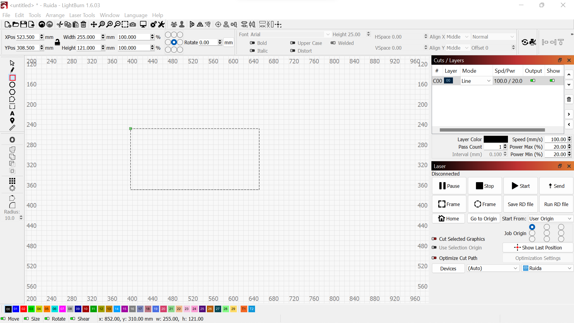
LightBurn is the software that drives the laser cutter, and it also has good drawing tools. I used its shapes and boolean tools to build a real estate logo from simple parts.
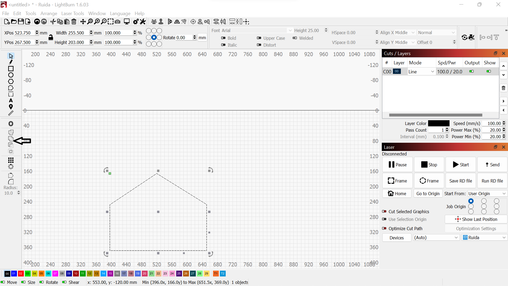
- Opened LightBurn and looked at the drawing tools on the side.
- Drew a rectangle as the base of the logo.
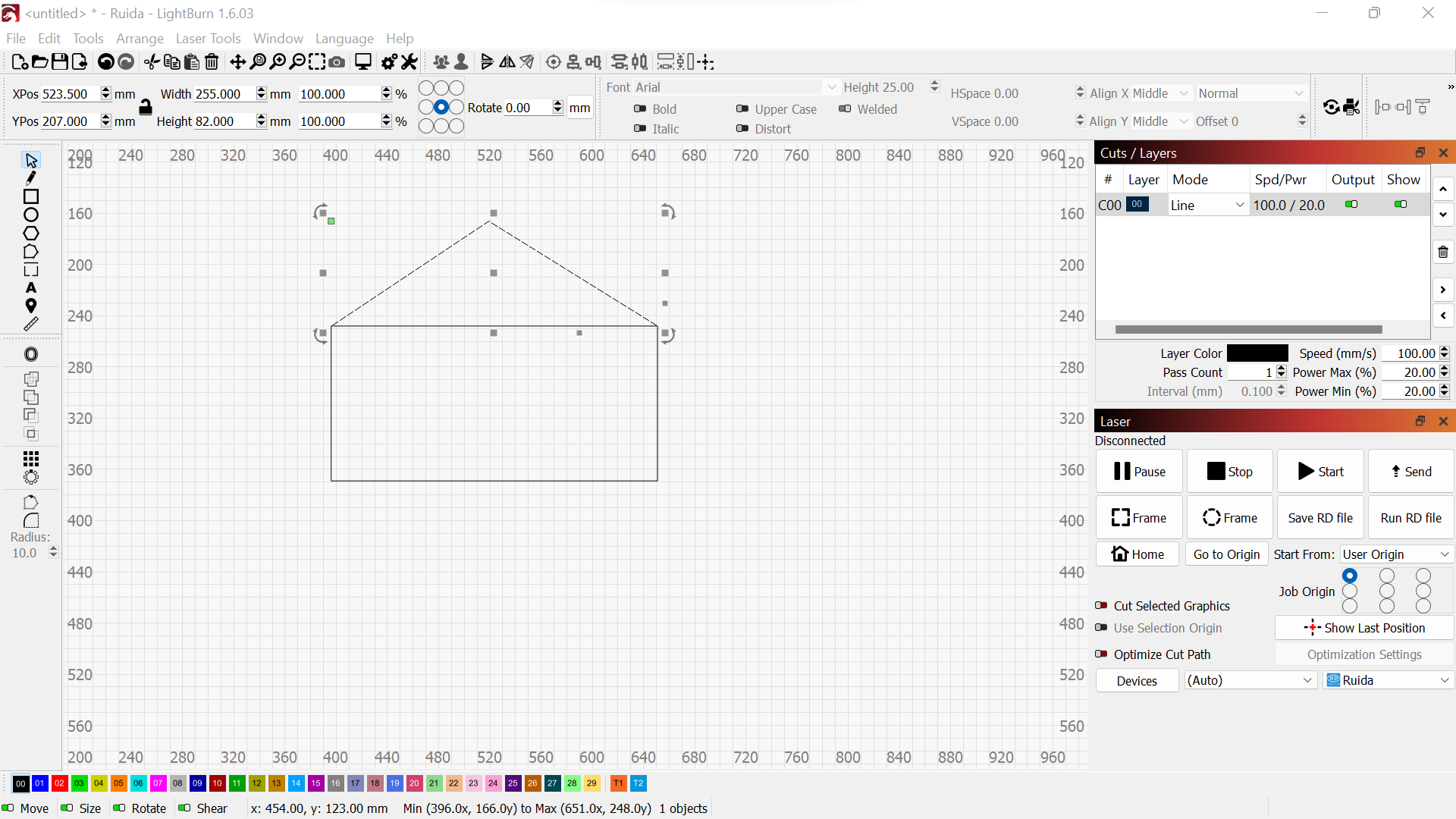
- Added a triangle on top of the rectangle to suggest a roof.
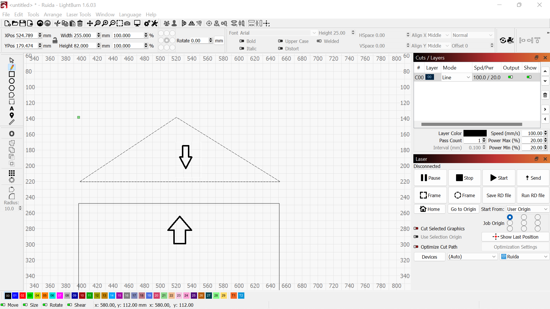
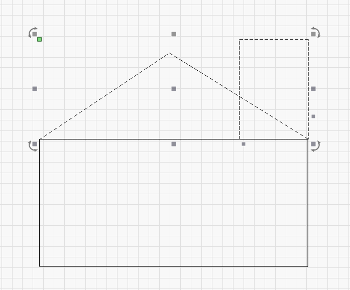
- Arranged the triangle and rectangle into a house shape.
- Used the union tool to join them into one solid shape.
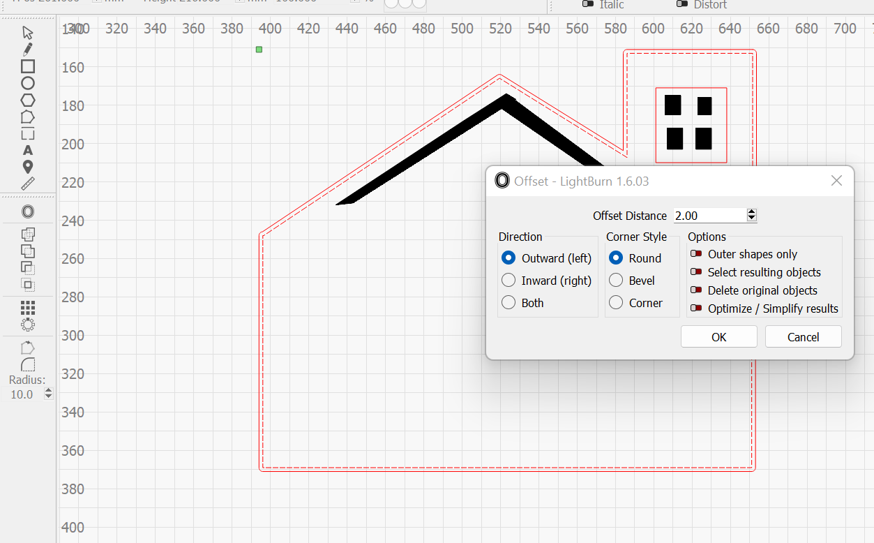
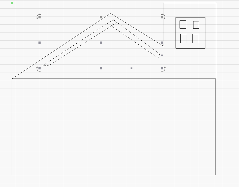
- Used offset to add a clean outline around the shape.
- Finished the logo, ready to send to the laser.


Modelling a part in SolidWorks
3D design is where I build a real part on the computer that I can later print or machine. SolidWorks works the way most 3D tools do: you draw a flat sketch, then give it thickness, then keep adding features. Here is the full process I followed to model a simple part, step by step, so anyone can repeat it.
Step 1, Start a new part
I opened SolidWorks and created a new Part file. A part is a single solid object, which is what I want here.
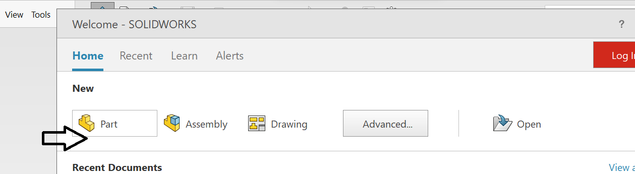
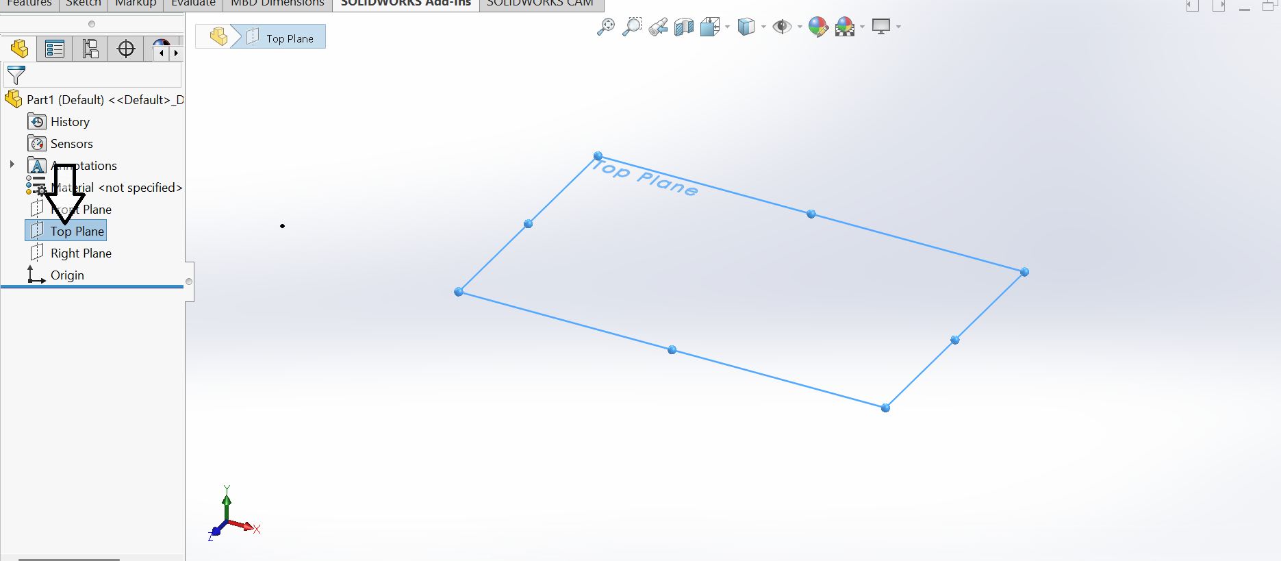
Step 2, Pick a plane to draw on
Every sketch needs a flat surface to start from. SolidWorks gives three planes, Front, Top and Right. I chose the Top plane because it suited the shape I wanted to draw.
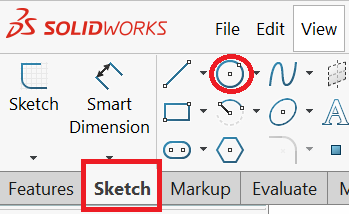
Step 3, Open a sketch
With the plane selected I entered sketch mode. Sketch mode is where I draw the flat 2D outline that the 3D shape will grow from.
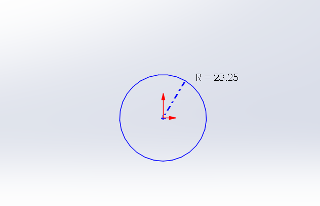
Step 4, Draw the shape
I drew a circle as my base shape using the circle tool.
Step 5, Add dimensions
A sketch is only useful when it has exact sizes. I used the smart dimension tool to set the diameter, so the shape is precise instead of roughly drawn. When a sketch is fully dimensioned it stops moving around, which means it is fully defined.
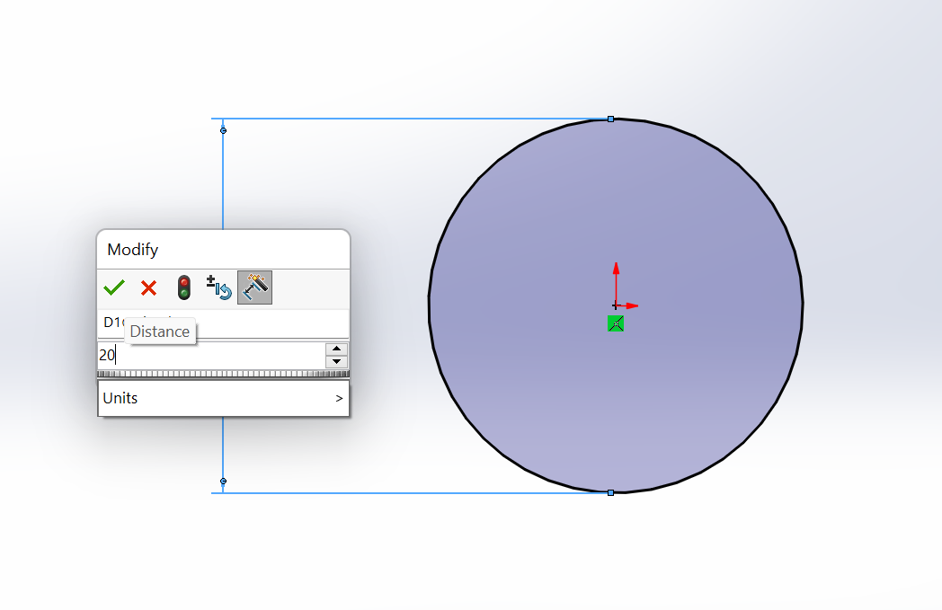
Step 6, Extrude into 3D
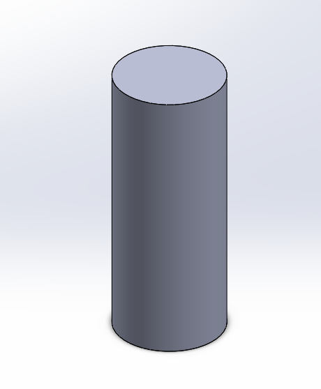
This is the moment the flat drawing becomes a solid. I used the Extrude feature, which pulls the sketch upward by a thickness I choose. The flat circle became a solid cylinder.
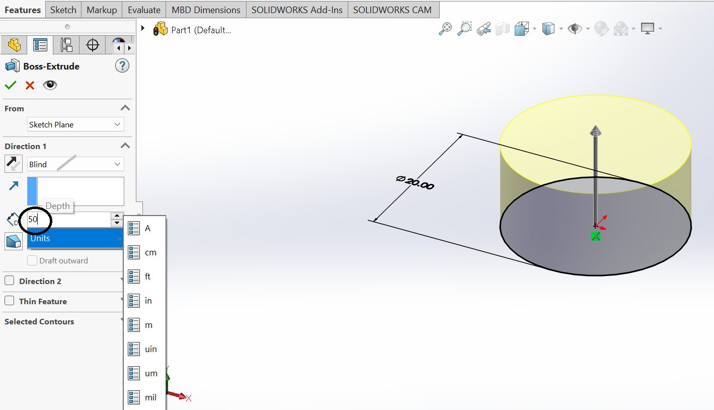
Step 7, Save and export
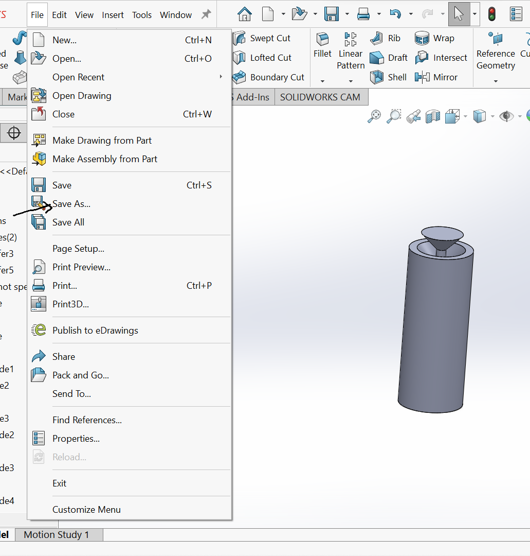
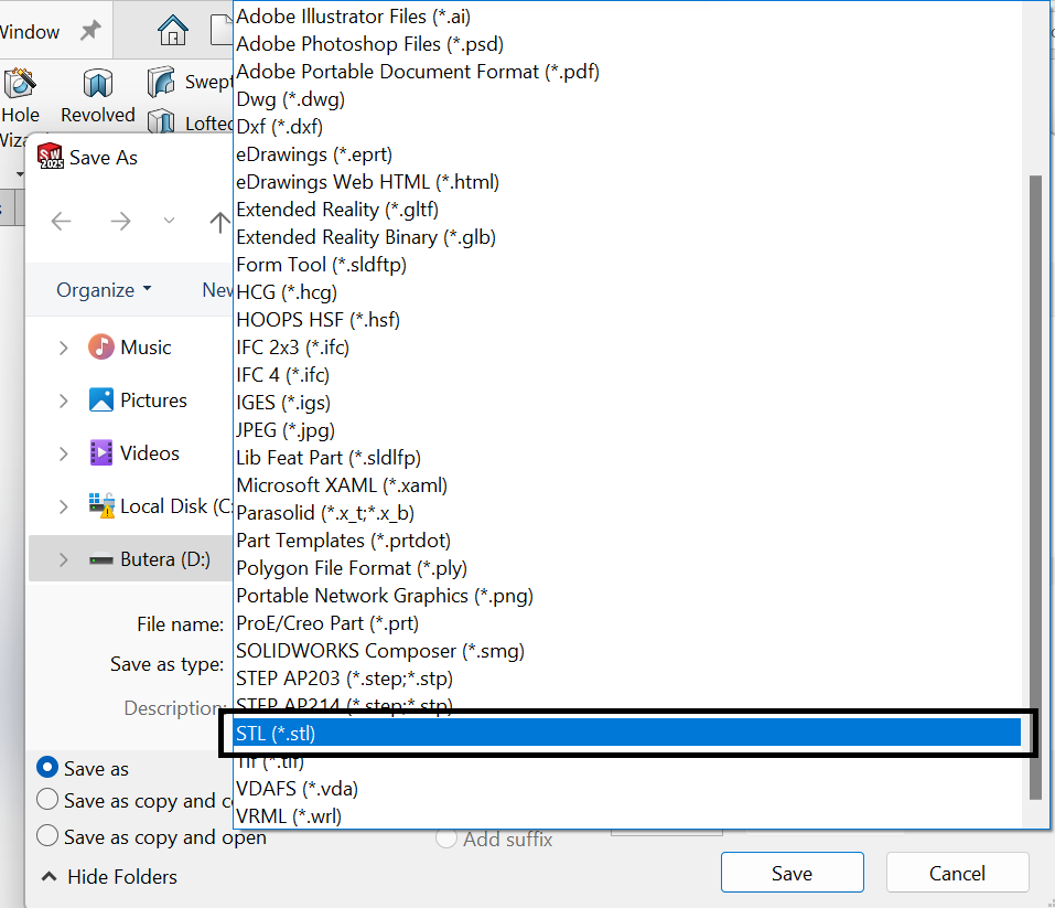
I saved the design in the SolidWorks part format so I can keep editing it later. Then I used Save As to export an STL file, which is the format a 3D printer can read.
For the rendered look of my model I used Renderair alongside SolidWorks, which adds realistic materials and lighting so the part looks like a real object instead of a flat grey shape.
Compressing images and video
Before putting everything online I made the files smaller so the page loads fast. A few of my raw files were several megabytes each, which is far too heavy for a website. Here is exactly what I did, the tools I used, where to get them, and the real sizes before and after.
The tools I used and where to get them
I used two free tools, one for images and one for video. Both are free and safe to download from their official site.
- Squoosh for images. It runs inside the browser, so there is nothing to install. I open squoosh.app in Chrome, drag an image onto the page, set the width on the right side panel, choose MozJPEG with the quality slider near 80, and click the download button. For a quick resize I also used Windows Paint, which is already on every Windows machine: open the image, click Resize, set the width in pixels, then Save As and pick JPEG.
- HandBrake for video. It is a free, open source video compressor. I downloaded it from handbrake.fr, ran the installer, and opened it. The exact settings I used are in the Video steps below.
Images
My biggest images were the camera photos and a couple of full screen captures. They came out at 2 to 2.3 megabytes each. My method for each one, using Squoosh (or Paint for a fast resize), was the same:
- Open the image and check its real pixel size, which was much larger than the page needs.
- Resize the width down to about 1600 pixels, since the page never shows an image wider than that.
- Save it as a JPG at about 80 percent quality, which trades a tiny bit of detail you cannot see for a much smaller file.
- Compare the new size to the old one to make sure it actually dropped.
Most of my SolidWorks screenshots were already light, between about 20 and 215 kilobytes, so I left those alone. The work was on the heavy ones. The table below shows the files that were genuinely too big and what they became.
| File | Before | After | How |
|---|---|---|---|
| extrudee.jpeg (extrude photo) | about 2.3 MB | under 300 KB | Resize to 1600 px wide, save as JPG at 80 percent |
| mylogo.jpg (laser logo photo) | about 2.1 MB | under 300 KB | Resize to 1600 px wide, save as JPG at 80 percent |
| printed.png (printed part photo) | about 786 KB | under 300 KB | Resize and save as compressed JPG |
Video
My screen recording of the Inkscape trace, tracing.mp4, was the heaviest file of all at about 15 megabytes. A clip that size makes a page crawl on a slow connection. I compressed it with HandBrake (free, from handbrake.fr), a tool made for exactly this:
- Open HandBrake and load tracing.mp4 as the source.
- Pick the Fast 1080p30 preset, which sets a sensible quality and a 1080p size.
- Set the video to H.264 with an RF quality around 22, where a higher number means a smaller file.
- Encode, then check the new file is far smaller while the clip still reads clearly.
The same H.264 plus RF 22 recipe works for any short screen recording, so I reuse it for every clip I post.
My design files
These are the original editable files from this week so anyone can open and reuse them. Each one is the real working file, not a flat picture of it.
