Week13
Molding and Casting
Group assignment:
- Review the safety data sheets for each of your molding and casting materials
- Make and compare test casts with each of them
- Compare printing vs milling molds
Individual assignment:
- Design a mold around the process you’ll be using, produce it with a smooth surface finish that does not show the production process toolpath, and use it to cast parts.
Group things
This is where our group page is.
https://fabacademy.org/2026/labs/nagoya/assignments/week13/
I learnt harmful substances in silicone and resins and why silicone and resins hardens.
A prequel story
I recently 3D printed “Rheostat Knobs - Cessna 172 Flight Simulator” and edited because original model was too loose for my potentiometer shaft.
Luckily, original designer shared FreeCAD file in distribution archive, I opened it with FreeCAD and exported to STEP file. And I opened it with Fusion and edited diameter of holes.
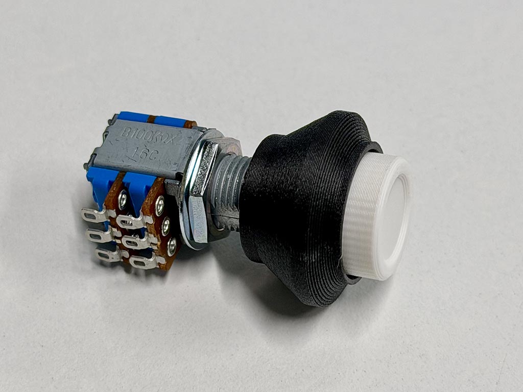
After a few times diameter change, I finally got 3D printed knob that fit to my potentiometer.
What to cast
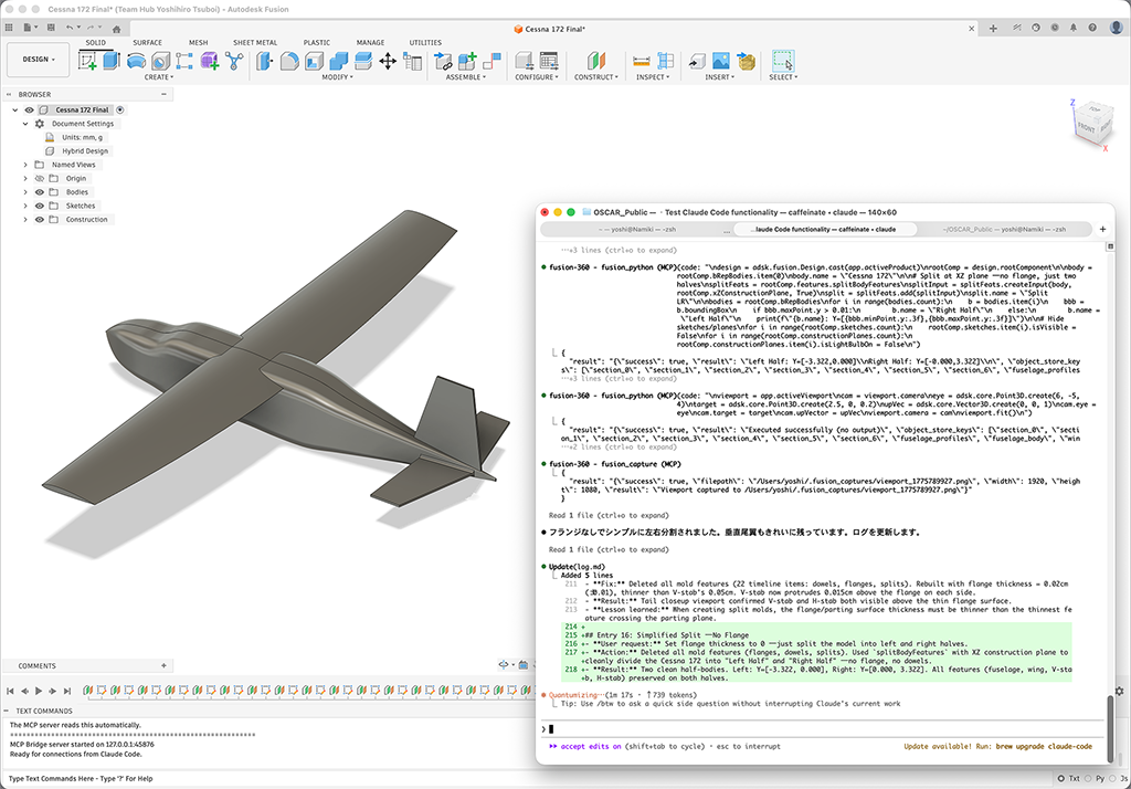
For the theme for assignment this week, I initially thought about to cast a small airplane model. And for researching purpose, I tried to let Claude Code to draw a Cessna 172 model with Fusion. But I found it is too hard to make milling mold.
If you are interested in this, I played with OSCAR — Open Source CAD Automation Claude Code and Autodesk Fusion 360. There are FreeCAD MCP and BlenderMCP.
So, I changed plan to cast the knob.
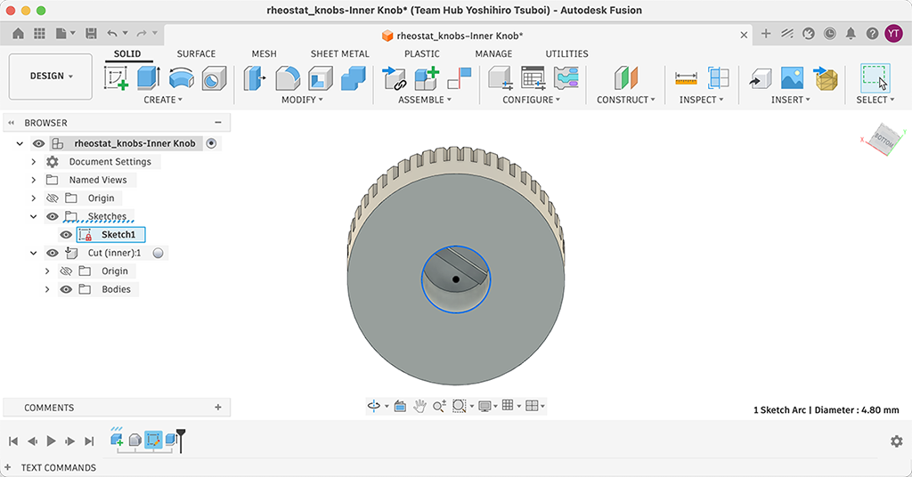
Draw a mold
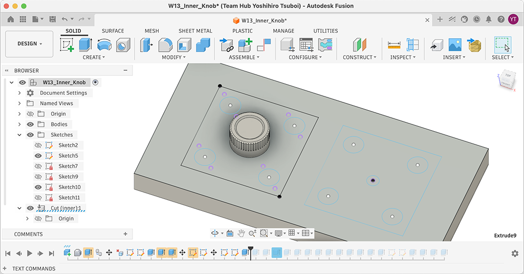
So I copied the inner knob data and draw a sketch on a bottom surface of the knob. Because the knob have a hole for fixing to the potentiometer shaft, the mold need to be a two part mold.
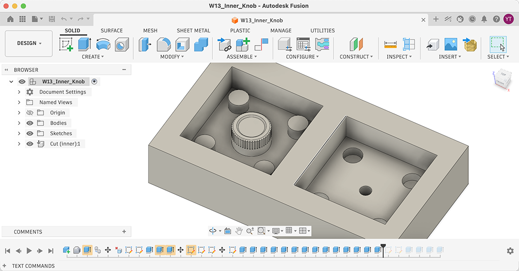
The hole need to be a center of the knob, so I put dowel holes and plugs to align two molds. Since I’m thinking about to use silicone gum, I believed I can pull silicone mold out easily by its flexibility. So I extruded frames and dowel holes and plugs.
I thought about to put gates for in (resin) and out (air), but I skiped this process because I was not sure if I can carve out a few millimeter dia. long cylinders with CNC milling without breaking. So, I decided to put plastic cylinder bar to make gates when I make silicone mold.
CAM
The last issue was CAM software. I usually amn’t using CAM function of Fusion because it looks to complicated, but I decided to try Fusion CAM at this time.
To use CAM function on Fusion, change the workspace from DESIGN to MANUFACTURE. You can change it by big button let top of the window.
Then, goes to SETUP and choose a machine. At this time, I choose Autodesk Generic 3-axis the most similar machine we are going to use. For Post processing, I choose Grbl / grbl because this machine uses grbl for milling controller.
Next, we need to add tools (endmills). To add endmills, goes to UTILITIES tab - [MANAGE] - [Tool library].
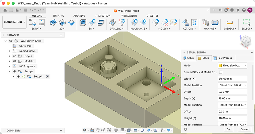
Next is applying Stock. Since we are going to use 178 x 78 x 40 mm wax cube, I entered these numbers on Stock tab of Setup window. We can setup the position of work on material on this tab.
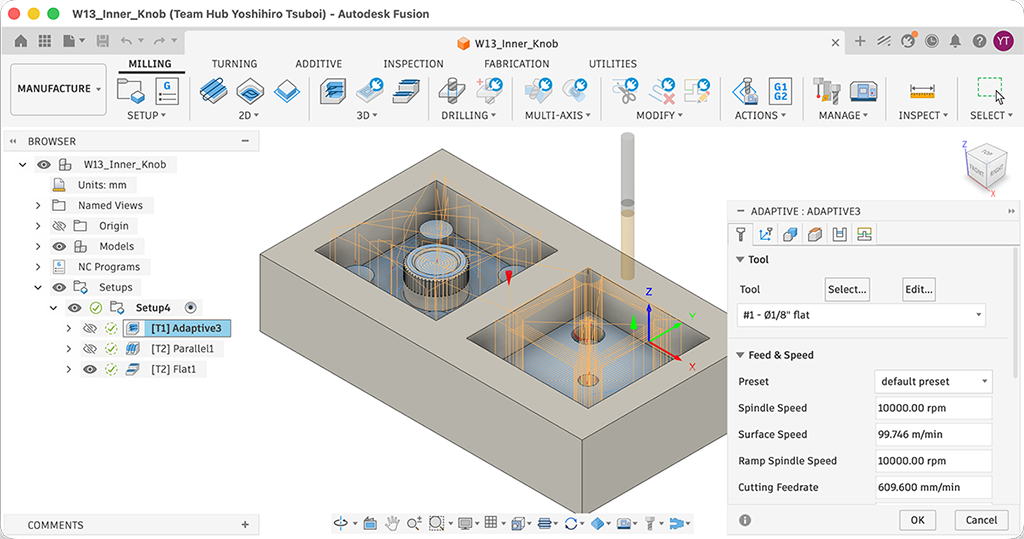
To generate a toolpath, MILLING tab - [3D] - [Adaptive Clearing]. This is for rough machining. For finish machining, MILLING tab - [3D] - [Parallel]. So that we have two g-code tiles, one is for rough, the other one is for finishing.
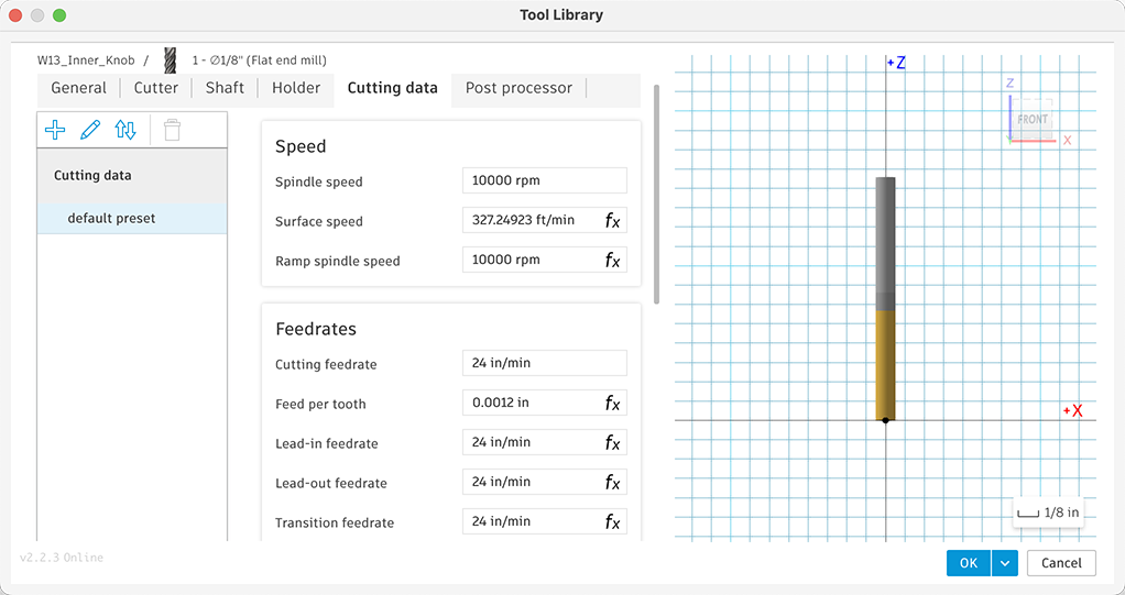
For roughing, I use 1/8” flat endmill. For finishing, I use 0.9 mm flat endmill. Because 1/8” ball endmill is too thick for finishing my design, I used the thinnest endmill we had on hand that had the necessary cutting length for the machining process. Parallel1 in the picture is the toolpath for 1/8” endmill. Flat1 is toolpath for 0.9 mm endmill. I used 24 in/min for feedrate.
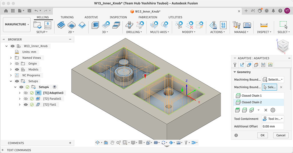
One tip, when you generate toolpathes, you’d better to set Selection on Machining Boundary at Geometry tab, and choose Machining Boundary Selection. Otherwise, generated tool path may mill outer side of the mold.
Original design file: W13_Inner_Knob.f3d
Milling
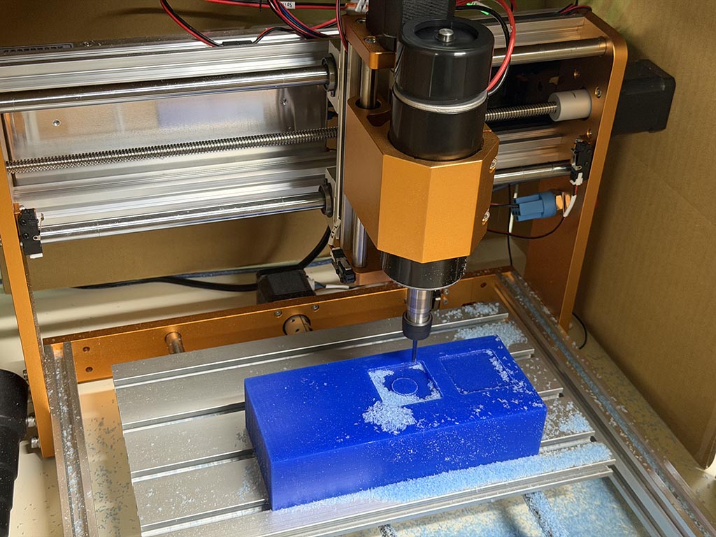
I used Candle to send g-code to machine again. I fixed wax cube with double sided tape and milled.
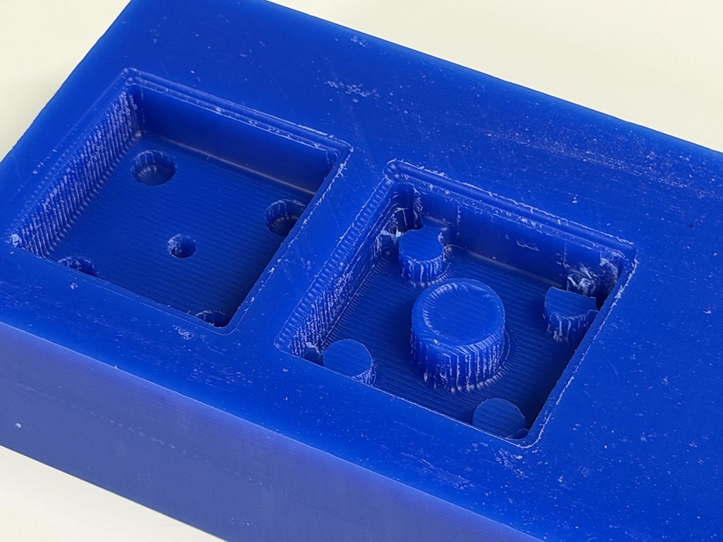
Done. One of the Dowel hole had crack during milling process. I found if I had more space between dowel hole and wall because it was connected. But it’s ok, it looks dowel hole still can do required function.
Printing
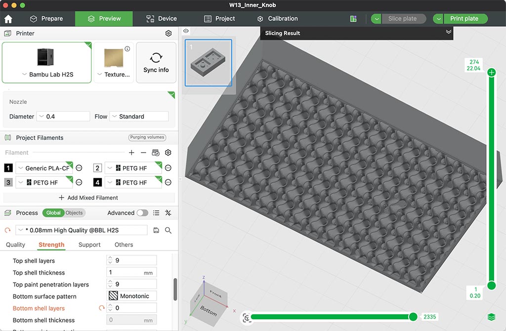
To complete a group assignment task Compare printing vs milling molds, I printed the mold. Because I’m going to use vacuum chamber to degassing, I thought I’d better to make it non-airtight. So I removed bottom shell layer and made it open-air.
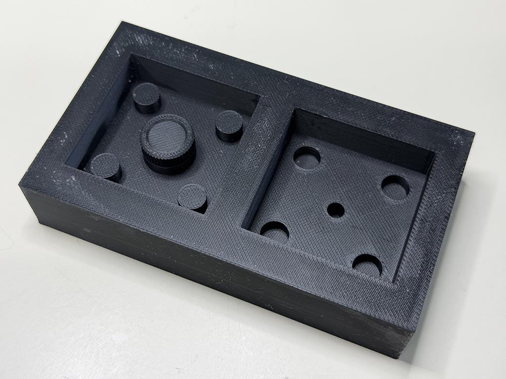
To make a fine mold, I printed with 0.08mm layer height. For other parameters, 3 wall loops to avoid leakage, normal 15% infill, used Bambu HS PETG.
Safety
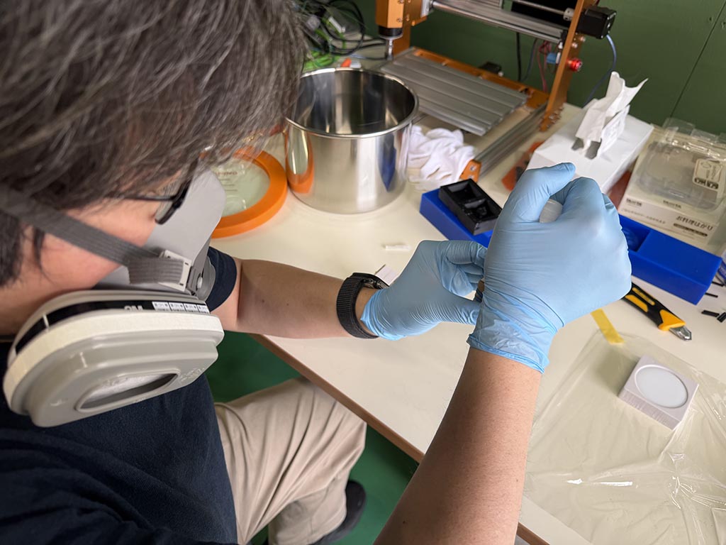
Because one of my known maker got resin allergy through makeing blinky resin accessories, I’m so nervous about resin allergy. I purchased 3M 6001 Organic Vapor Filter Cartridge and 6000 mask.
Of course, wearing nitrile gloves and glasses.
Making silicone mold
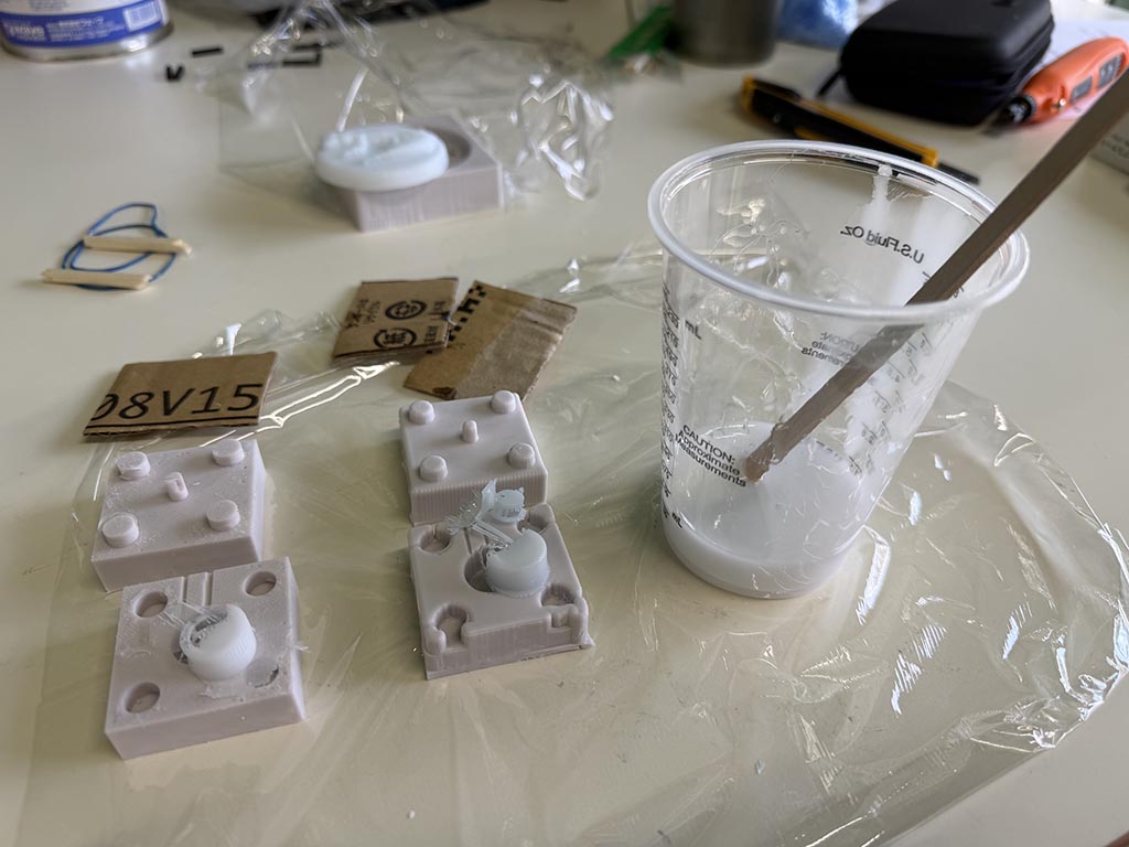
We are using “Wave silicone gum”, as on our group page.
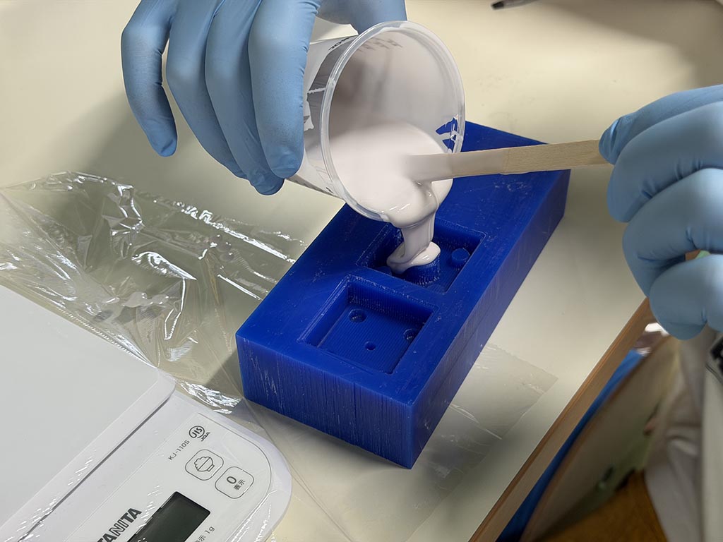
We mixed up base and curing agent, and poured into wax cast and 3D printed cast.
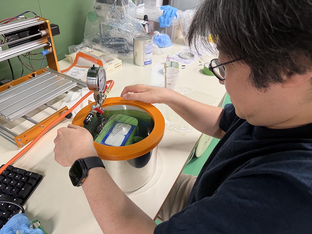
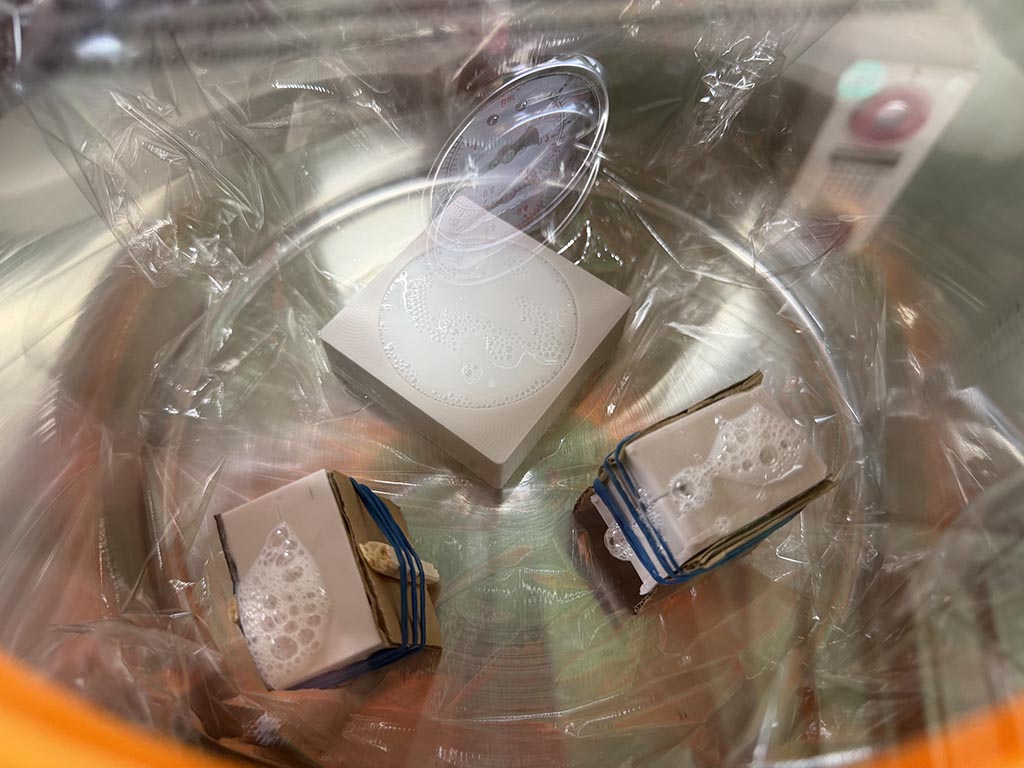
And put into vacuum chamber for degassing.
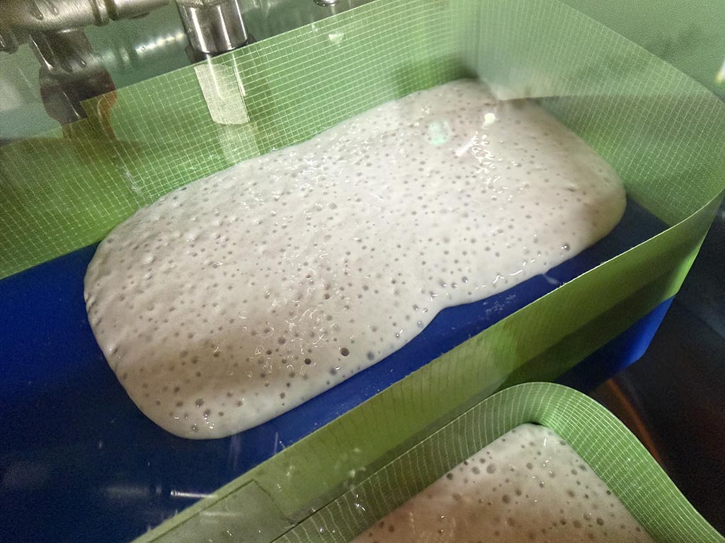
We mixed and poured gently but so many bubbles came up.😲
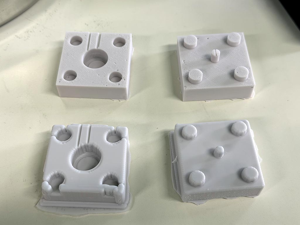
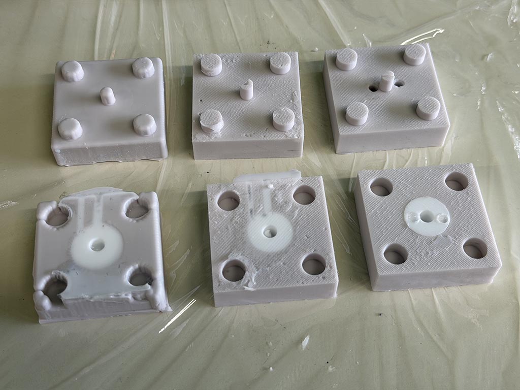
About 18 hours later, we tried to get silicone molds. Upper two are from 3D printed mold, lower two are from milled mold. 3D printed mold clearly output precise silicone mold in my case. I may need to use really thin endmill to make precise mold.
I forgot to put round bars to make gate and air hole. I remember this just after pouring mixed silicone gum. So I made those with utility knife.
Comment from global instructor
Few trick for avoiding the bubble formation: - Degass before molding. - “Paint” using silicone with a brush the surface of the mold.
Surface finished 3D mold
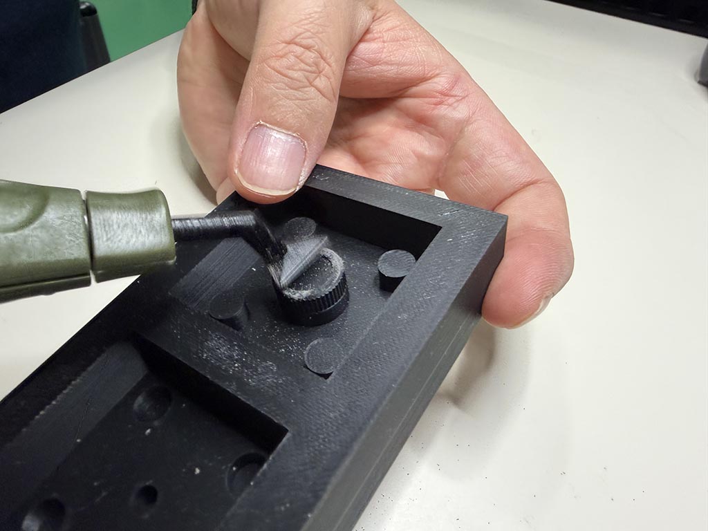
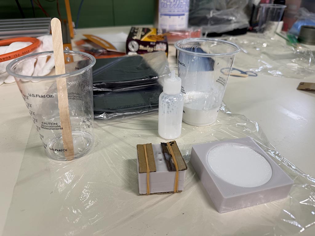
After start casting, I tried to finish the surface of 3D printed mold.
And poured mixed silicone. I did’t forget to put round bars.👍
Epoxy casting
I tried to cast with “SANAAA White epoxy resin”.
I tried to inject mixed resin by using needle bottle, but mixed resin was too hard to inject.
So I changed plan to just pouring.
And put into vacuum chamber for degassing.
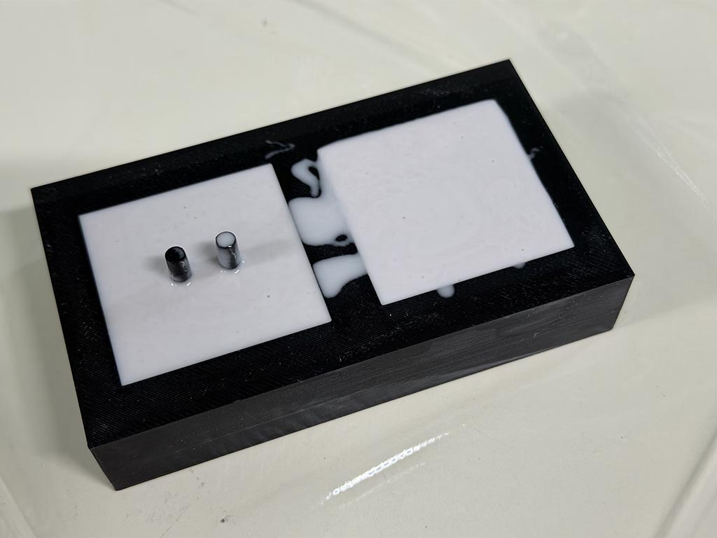
About 24 hours later, I opened mold and was disapointed. Probably because high viscosity of mixed epoxy resin, mold wasn’t enough filled up.
Urethane casting
I tried to cast with “Wave resin cast Ex.”.
I thought its 120 second setting time is not enough for degassing, but it was enough.
10 something minutes later, I opened up molds. From left to right, wax, 3D printed, 3D printed surface finish mold.
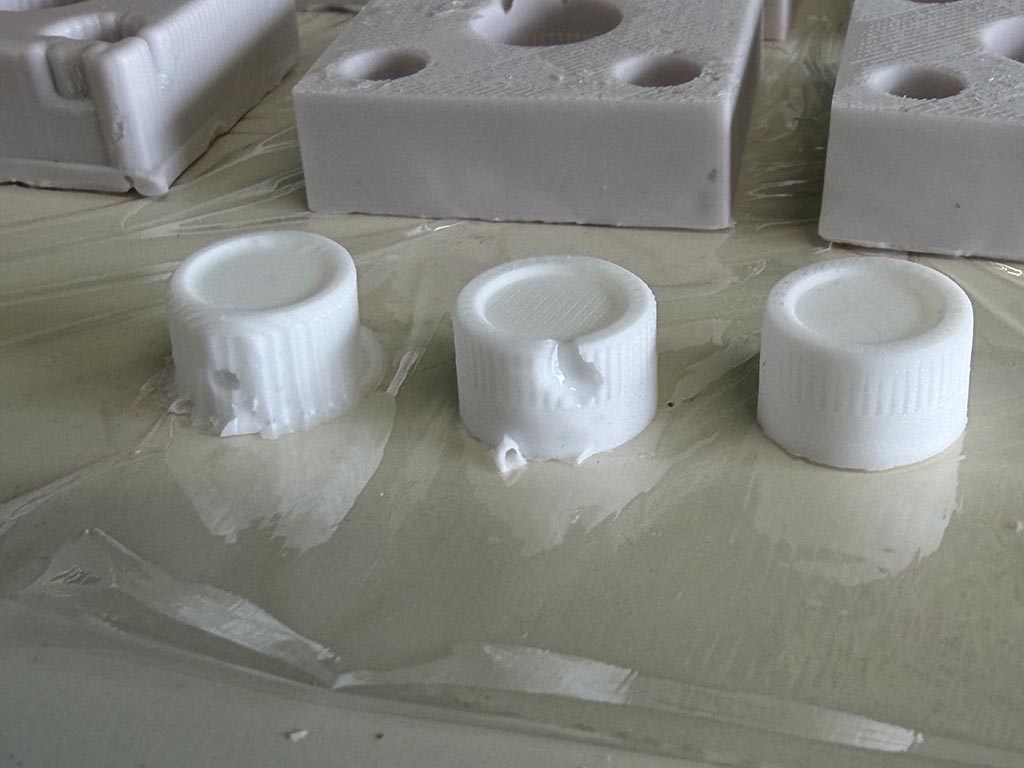
From left to right, wax, 3D printed, 3D printed surface finish mold. Wax mold can not reproduce grooves and sidewall. We can see traces on top of non surface finished 3D printed mold one. There are no traces on surface finished 3D printed mold, but it looks I sand too much when surface finishing. Grooves got thinner.
There are bubbles on left two. This is because I forgot to put round bar when I make silicone mold. Gate positioning and size are very important, this is what I learnt.
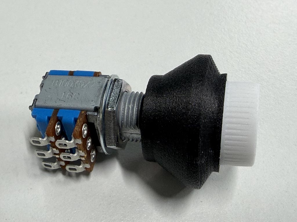
Anyway, I picked up well done one, from surface finished 3D printed mold one, and assembled with potentiometer.
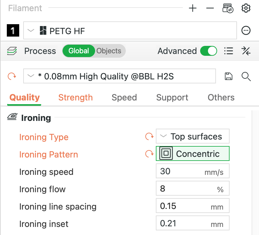
Because I 3D printed with 0.08mm layer height, I am happy with the quality of the 3D printed mold except traces on top layer. And after that, I remember if I enabled top layer ironing option. So that I could omit surface finishing process.
Checklist
- Linked to the group assignment page and reflected on your individual page what you have learned
- Reviewed the safety data sheets for each of your molding and casting materials, then made and compared test casts with each of them
- Documented how you designed and created your 3D mold, including machine settings
- Ensured your mold has smooth surface finish, that does not show the production process (by postprocessing if necessary)
- Shown how you safely made your mold and cast the parts
- Described problems and how you fixed them - Here
- Included your design files and ‘hero shot’ of the mold and the final object