Week06
Electronics Design
Assignment
Group assignment:
- Use the test equipment in your lab to observe the operation of a microcontroller circuit board (as a minimum, you should demonstrate the use of a logic analyzer)
- Document your work on the group work page and reflect what you learned on your individual page
Individual assignment:
- Use an EDA tool to design a development board that uses parts from the inventory to interact and communicate with an embedded microcontroller
Group assignment
Our group assignment is on lab’s page. Since I lead group assignment, there are nothing special learned. If I had to say it, I found price of Saleae logic got so higher than when I purchased.
What I made
Since I may need to connect input/output things during the class, I thought I’d better to make MCU board that can change peripherals. For those purpose, Seeed Grove is good solution. Fortunately, we have a lot of Grove modules in our office and can lend to lab.
So, that the board I’m going to make have connectors for Seeed XIAO and Seeed Grove. For XIAO, I bought 7 pin 2.54 mm pitch SMT female header FSM-41052-07. For Grove, Seeed is selling Grove Female Header - SMD-4P-2.0mm-90D.
Use an EDA tool
I’m EAGLE user for long time, but Autodesk announced their support will be end at 7 June 2026. So I need to choose where I go. One option is Fusion, the other is KiCad. I tried KiCad about 10 years ago and had bad feeling about that. But I’ve never tried Fusion EDA, so I will try Fusion this time.
Through this trial, I found these things.
- We can use EAGLE libraries directly.
- Positions of buttons are different from EAGLE, but operations are very common.
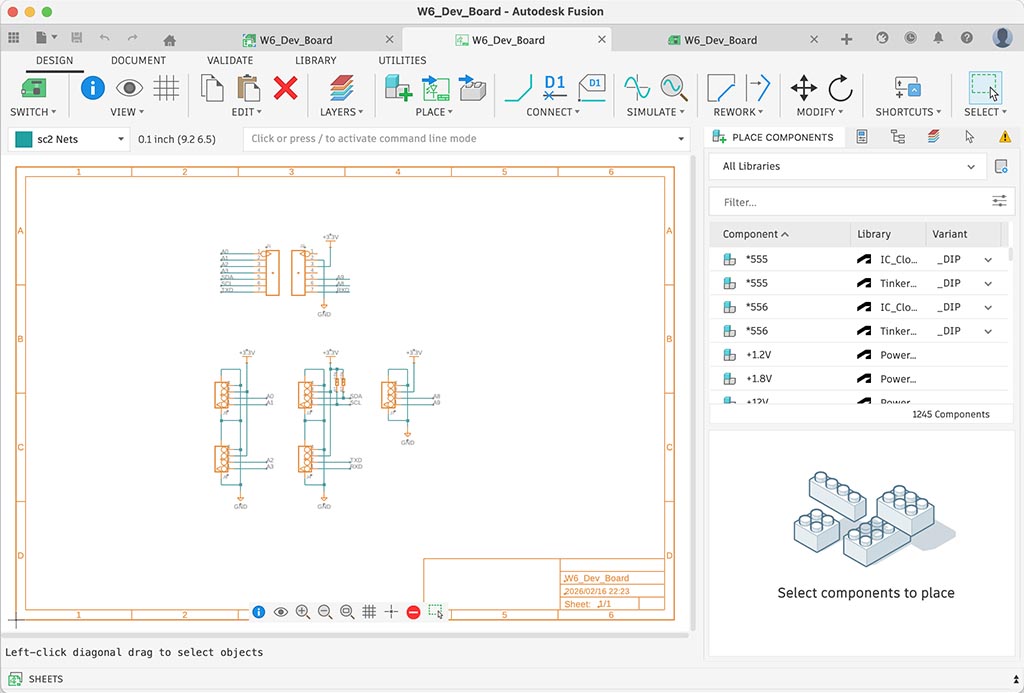
I could finish schematics drawing very quickly because I already have components library for everything. So, I used imported components library except power symbols. For power symbols, I used Power_Symbols came with Fusion.
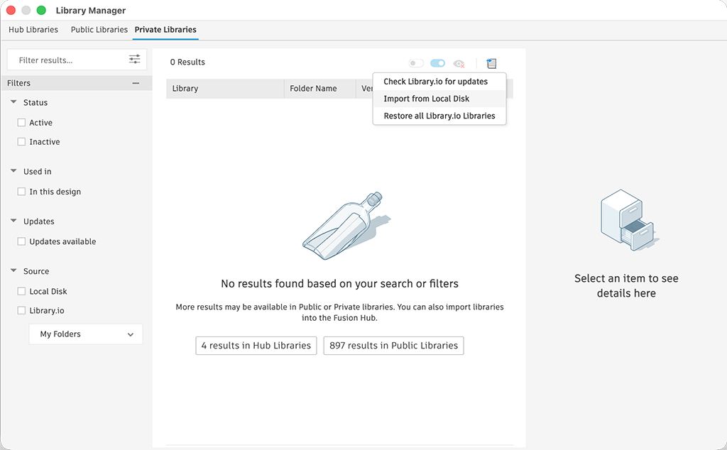
To import EAGLE library to Fusion, I just needed to import from local disk. Fusion could open EAGLE files as its original format. But since Fusion was designed to work with their cloud drive, so it was more like importing to cloud drive. It flustrating me a little bit, but there are some merit because I’m using multiple computer.
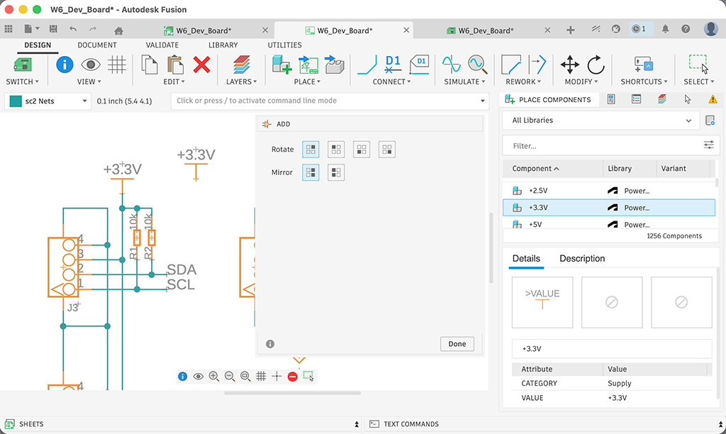
Once we have all component library on Fusion, I placed components on schematic by using PLACE button. To connect components with wires, uss CONNECT button.
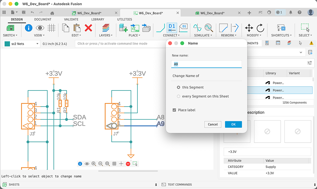
For the readability of schematic, I love to name connections. To name, right click the connecting wire and choose Name from menu. The name is the name of signal. In this case, it was connected to XIAO’s A9 pin, I named it as A9. By checking Place label, we can add a label. Otherwise there are nothing to see the signal name of each wires.
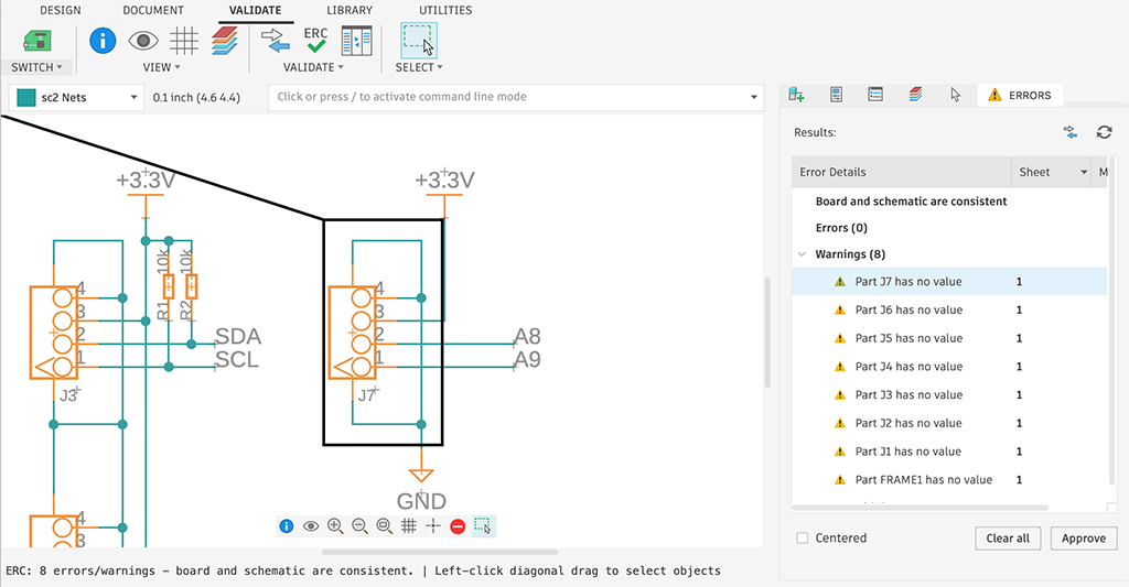
After finish drawing schematic, I ran ERC (Electrical Rule Check). I usually don’t do this, because ERC is only checking connections on schematic based on sat value on component library. I think it’s not checking electrical rule, it check sat value on component library.
Anyway, I ran this by assignment requirement and got some warning that values were not sat on placed components. So I approved those and ignored.
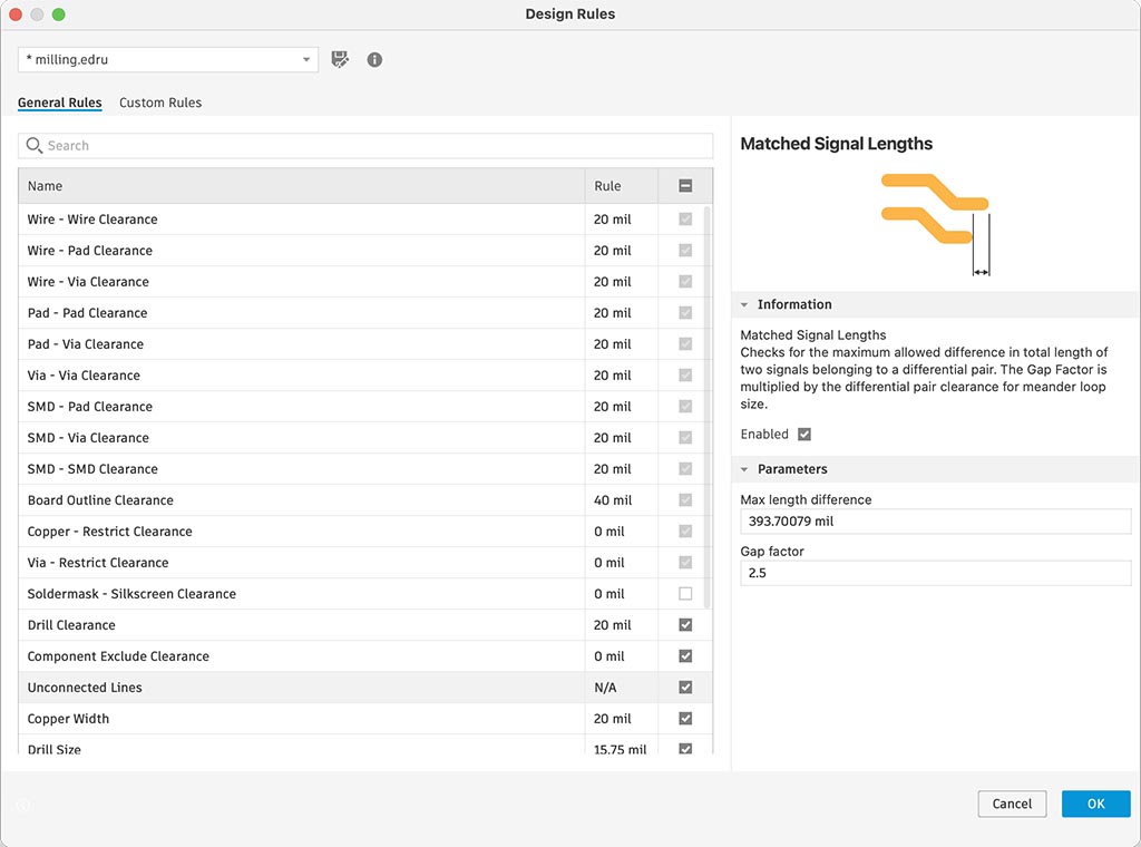
I found I’d better to have more than 20 mil trace width and clearance, so I setup design rule at first.
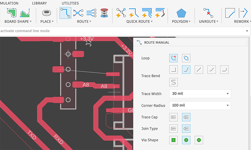
To connect wires on layout, I click ROUTE button and sat trace width as 30 mil because through it’s much bigger than 20 mil I mentioned above. Then, click a end of yellow thin wire and tried to draw a wire by moving mouse pointer. When we reach drawing wire to the other yellow wire end, one wire routing would be finished. We need to connect every yellow narrow wires, because it reflects connections on the schematic.
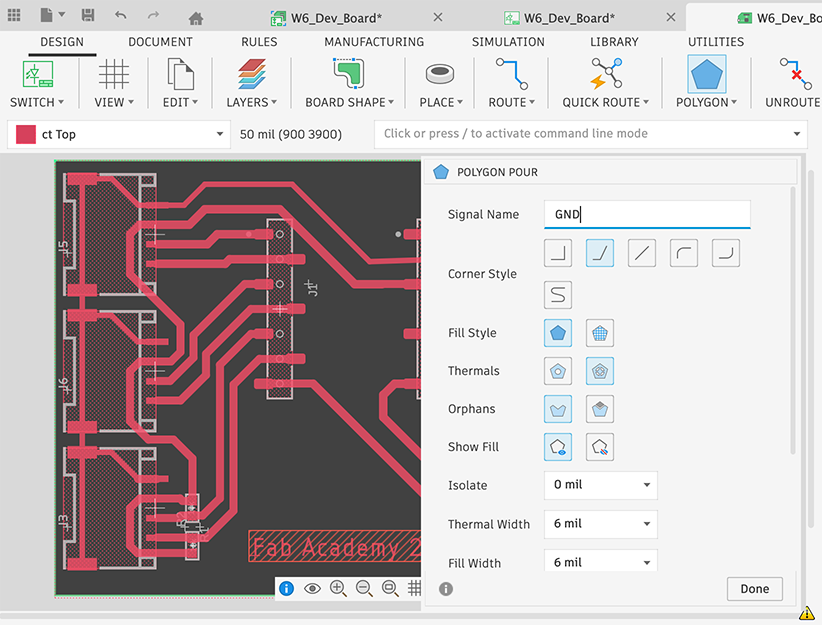
To draw a ground plane, we use POLYGON. I sat signal name as GND because it’s a signal name of power symbol. And then, draw a polygon to enclose the board shape. I think we’d better to set large value like 50 mil for Isolate for milled PCB.
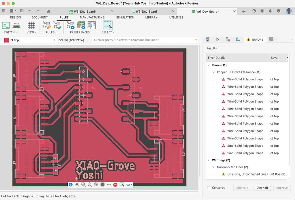
And I finished drawing PCB layout and then ran design rule check. There are no error for fabricate.
Files I designed are: W6_Dev_Board.sch, W6_Dev_Board.brd
When I try to save those files to local, I need to do “export”.  But we have “EAGLE 9.X compatible” option.
Problem
I didn’t have any problem on this week, but I had problem to install FlatCAM on my Mac. There are unofficial brew FlatCAM formula but it looks outdated.
The solution I choose are using MODS and/or other alternative solution.
What I learned
It’s super easy changing over to Fusion from Eagle. 
Checklist
- Linked to the group assignment page
- Documented what you have learned in electronics design
- Checked your board can be fabricated
- Explained problems and how you fixed them.
- Included original design files (Eagle, KiCad, etc.)
- Included a ‘hero shot’