Week15
System Integration
Learning outcomes:
- Design and document the system integration for your final project
Schedule
At mid term review (19 Apr)
| Item | Progress / Plan |
|---|---|
| Additional processing on original parts | Done |
| Making 3D printed parts | Done |
| Electronics (PCBs, wiring) | Done |
| Unit test | Done |
| Adding more input/output | - 6 May |
| Making enclosure | - 13 May |
| Making movie, finish documentation | - 6 June |
Now
| Item | Progress / Plan |
|---|---|
| Additional processing on original parts | Done |
| Making 3D printed parts | Done |
| Electronics (PCBs, wiring) | Done |
| Unit test | Done |
| Adding more input/output | Done |
| Making enclosure | Done |
| Making movie, finish documentation | - 6 June |
System diagram
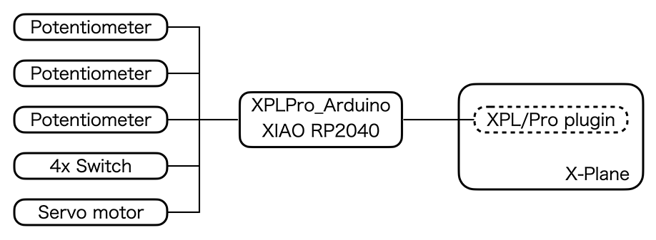
Here is the system diagram. There are three linear potentiometer and four switches for input. XIAO RP2040 read those input and send it as ascii protocol over USB serial. XPL/Pro plugin is running on X-Plane the flight simulation software and use those values as the input of simulated aircraft.
The great point of XPL/Pro is it can read/write DataRef (kind of internal parameter of X-Plane) from Arduino sketch. XPL/Pro plugin just do a bridge. So, XIAO can read flap position of simulated aircraft, and reflect it to the degree of servo motor.
Original plan
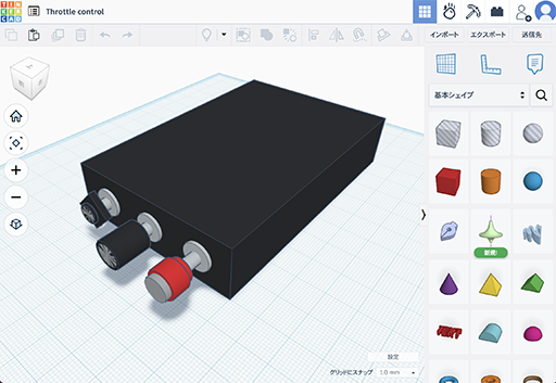
On the “Computer-Aided Design” week, I drew this picture with Tinkercad. But I decided to add flap switch and indicator after that, so I changed design of enclosure of the project.
Enclosure
Drawing
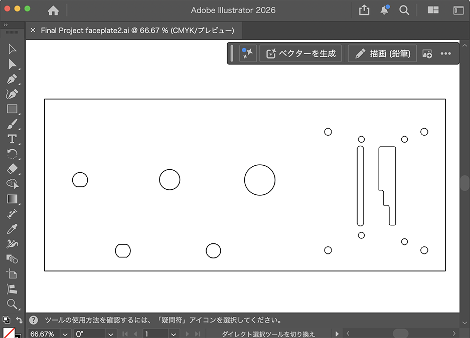
I purchased drawing of Cessna 172 panel to save time. And I made a drawing of face plate with Illustrator based on that, and I exported it as DXF.
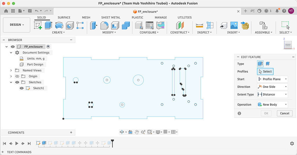
After that, I imported it to Fusion sketch. And edited the design for the panel of enclosure.
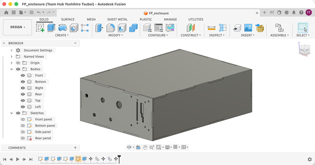
And then, I drew sketches for other planes and confirmed if it can be assembled. I exported confirmed sketches to DXF format.
Design file: FP_enclosure.f3d
Note
The laser cutter software in our lab can not reproduce outline of planes. Maybe it is because the outline is spline. My friend fixed this issue by using [explode] command on Dassault Systems DraftSight, but I don’t have it. So I tried to open the exported DXF file with Adobe Illustrator and re-exported as DXF, and it works.
Cutting
I cut t=4 mm MDF with laser cutter. The parameter was speed: 8, power: 50%. Unfortunately, I forgot to take a picture during laser cutting.
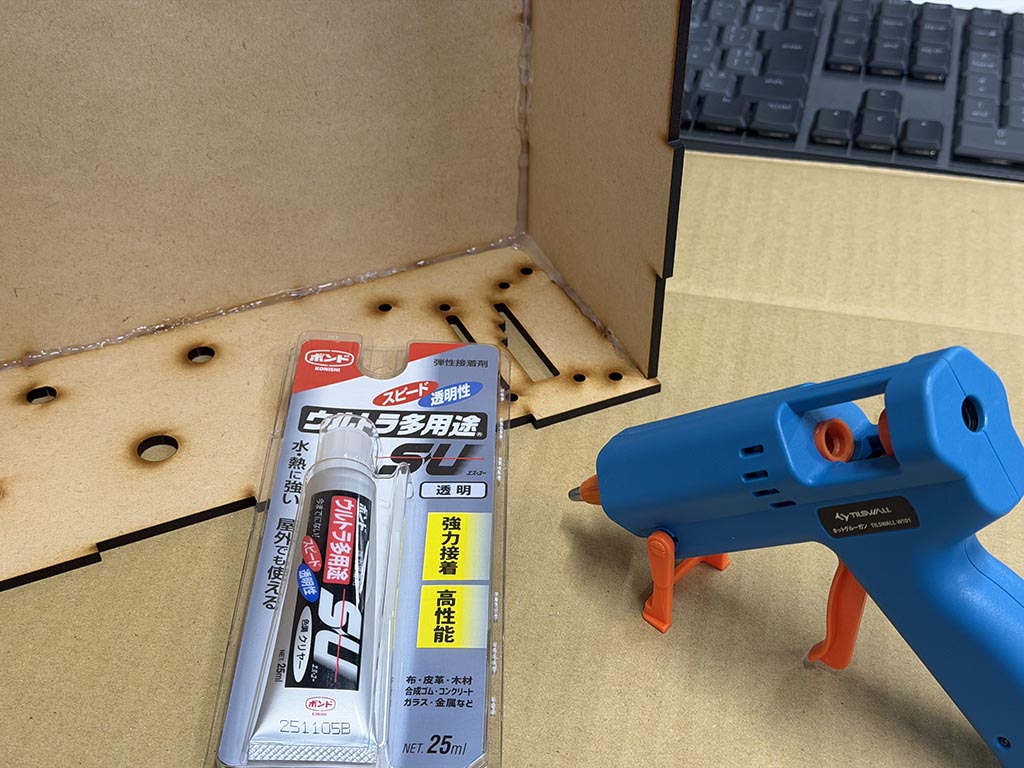
After that, I built enclosure box with glue and glue gun.
Painting
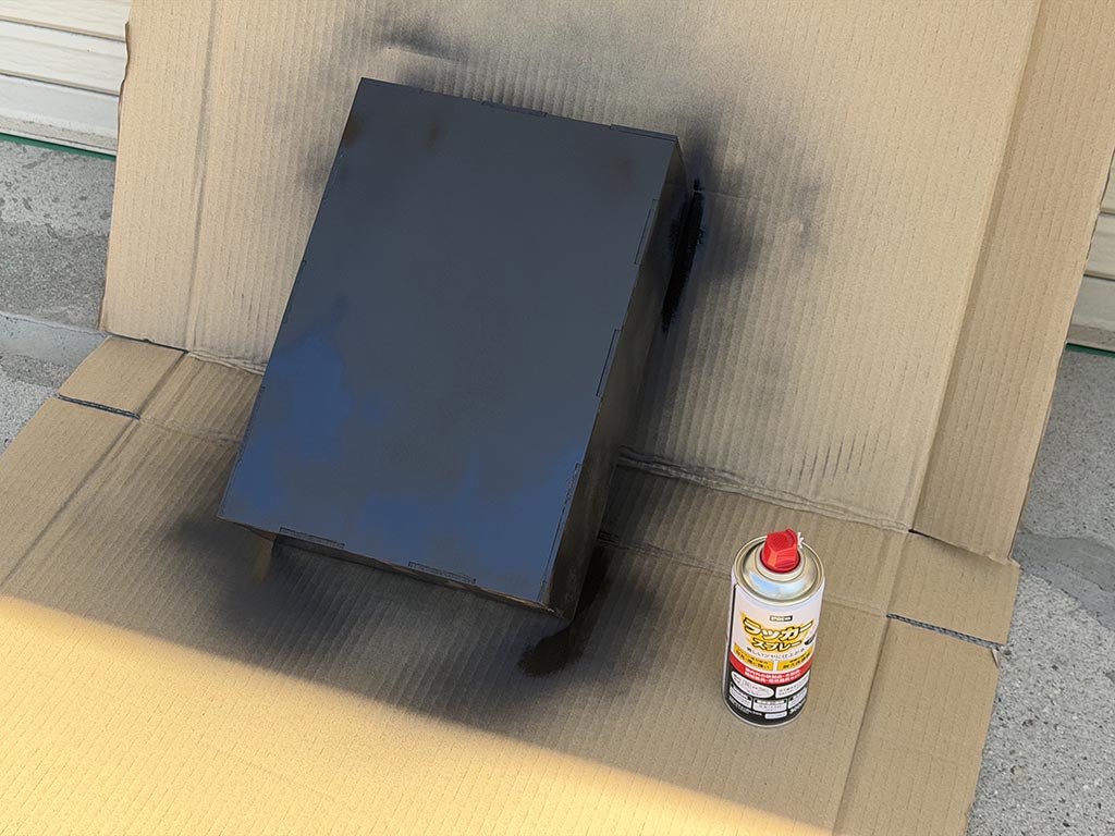
On next day, I painted with matt black lacquer spray.
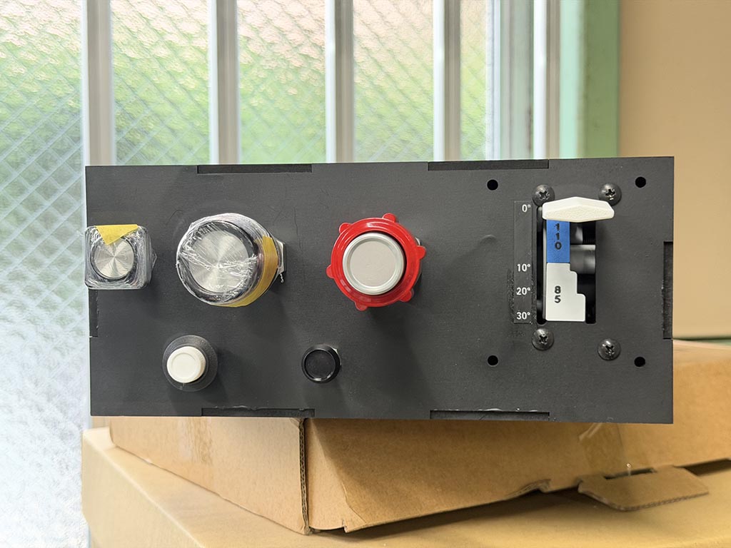
Put together

Finally, I put things together.
I tried to make marking with vinyl cutter at first. But I was unhappy with the quality of it.
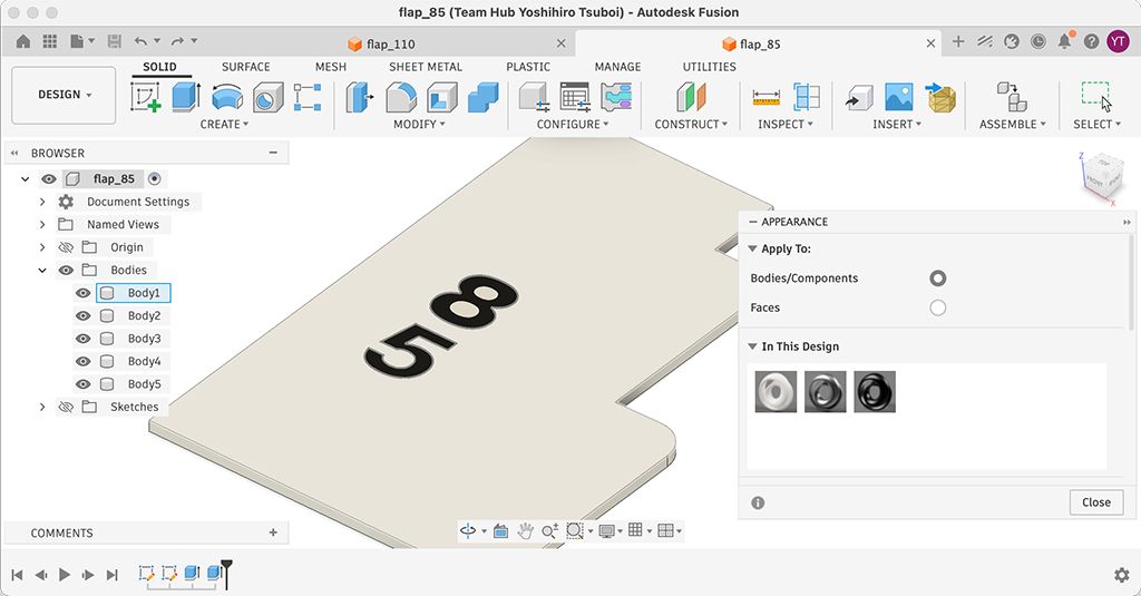
So I imported markings DXF to Fusion and made t=0.5 mm plate. Then printed with 3D printer.
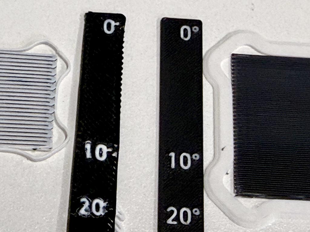
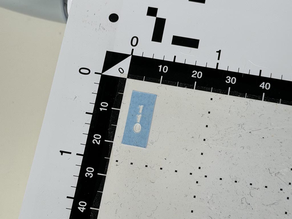
Because ° is too small to 3D print with 0.4 mm dia nozzle, I needed to change nozzle from usual 0.4 mm dia one to 0.2 mm dia one. Left in the picture was printed with 0.4 mm nozzle, right was printed with 0.2 mm nozzle. In my experience, changing 3D printers hotend is really tough work but it was so easy to change hotend of Bambu Lab P2S printer.
And put that plates with glue. Finally, I made it.
Design files: W15_flap_110.f3d, W15_flap_85.f3d, W15_flap_degree.f3d
Repairing
I got a feedback during the class that I need to fix PCBs, so I designed and 3D printed spacers and fixed PCBs.

Design files: W15_Pot_spacer.f3d, W15_PCB_spacer_A.f3d, W15_PCB_spacer_B.f3d
Checklist
- made a plan for system integration for your final project?
- documented your plan with CAD and/or sketches for system integration?
- implemented methods of packaging?
- designed your final project to look like a finished product?
- documented system integration of your final project?
- linked to your system integration documentation from your final project page?