Week10
Output Devices
Group assignment:
- Measure the power consumption of an output device.
- Document your work on the group work page and reflect on your individual page what you learned.
Individual assignment:
- Add an output device to a microcontroller board you’ve designed and program it to do something.
Group assignment
Our group assignment is on lab’s page.
Through this group assignment, I found the maximum peek current this servo cunsume is 403 mA. According to the schematics of XIAO RP2040, the voltage regulator of this board is RS3236-3.3YUTDN4. This regulator can supply up to 500 mA of output current, so we’d better to consider supply a power for this servo separately or using one only servo on this.
Making output device
I purchased C172 Flaps Lever CAD from 737DIYSIM to reduce my design work. Their build guide introduced swithch on eBay that without manufacturer name and MPN, but I prefer to use electronics components that has MPN for reproducibility.
The switch I purchased was Omron D2F-01FL2-T. Since this has a little different dimension from introduced eBay one, I modified this design a little bit and printed.
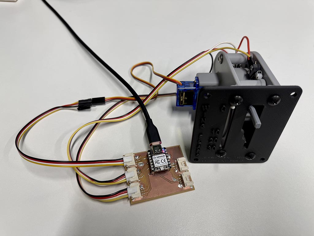
This is the one of the project I want to make, and I think servo of this project is good for the assignment this week. Servo that was used in the design was Tower Pro SG90.
I use Grove connector to be able to connect this device to microcontroller board I made at Week 8.
Wiring
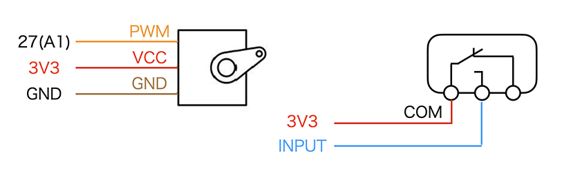
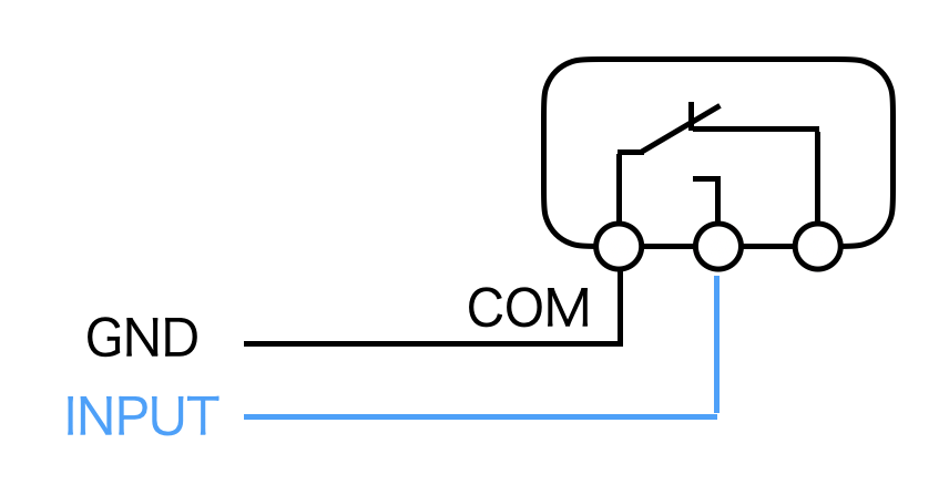
Since D2F-01FL2-T have both NO (normal open) and NC (normal close) terminal, we can do other wiring. I choose this way because there will no float state input if we do pull-up or pull-down a input pin. Also, with this wiring, we only need to wire two wires not three wires.
How servo work
Generally, the term “servo motor” refers to a motor capable of feedback control, but the servo motor discussed here refers to an actuator used in radio-controlled models and other applications, which can control the rotation angle of its axis (from 0 to approximately 180 degrees) using PWM.
PWM stands for Pulse Width Modulation, a technology that controls the power supplied to devices such as motors and LEDs by length of time the switch is ON.
In this case, we can specify the rotation angle by the length of time the switch is ON.
Sketch
#include <Servo.h>
Servo myservo;
int lastpos = 6;

void setup() {
  Serial.begin(9600);
  pinMode(29, INPUT_PULLDOWN);
  pinMode(28, INPUT_PULLDOWN);
  pinMode(7, INPUT_PULLDOWN);
  pinMode(6, INPUT_PULLDOWN);
}

void moveservo(int pos) {
  myservo.attach(27, 500, 2400);

  if (pos > lastpos) {
    Serial.printf("Move to %d\n", pos);
    for (lastpos; lastpos <= pos; lastpos += 1) { // to move slowly
      myservo.write(lastpos);
      delay(80);
    }
  } else if (pos < lastpos) {
    Serial.printf("Back to %d\n", pos);
    for (lastpos; lastpos >= pos; lastpos -= 1) { // to move slowly
      myservo.write(lastpos);
      delay(80);
    }
  } else {
    Serial.printf("Stay %d\n", pos); // if the lever stay, indicator stay
  }

  lastpos = pos;
}

void loop() {
  int a = digitalRead(29);
  int b = digitalRead(28);
  int c = digitalRead(7);
  int d = digitalRead(6);

  if (a==1) {
    moveservo(5); // Servo goes 5 degree if the switch position is retract
  } else if (b==1) {
    moveservo(32); // Servo goes 32 degree if the switch position is Flap 10
  } else if (c==1) {
    moveservo(43); // Servo goes 43 degree if the switch position is Flap 20
  } else if (d==1) {
    moveservo(52); // Servo goes 52 degree if the switch position is Flap 30
  } else {
    moveservo(5); // In other cases, move to 5 degree.
  }

  delay(1000);
}
By attach(27, 500, 2400);, I designated to use 27th pin, and 500 micro sec pulse width for 0°, 2400 micro sec pulse width for 180°. After that, servo library convert designated angle to pulse width and turn on a pin for calulated pulse length time.
It works!!
Integrating with flight simulator
Next, I try to connect this flap indicator to flight simulator by using Mobiflight. I choose Mobiflight because it support Raspberry Pi Pico 1, so I guessed I can use XIAO RP2040 with this. Second, since Mobiflight is open-source and its firmware is not so huge, I guessed I can look into this if I have trouble with it.
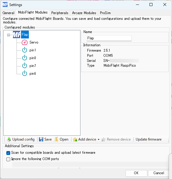
The hardware support of Mobiflight have interesting structure. Mobiflight flash pre-built firmware to microcontrollers, and our configuration will be uploaded as configuration from PC software.
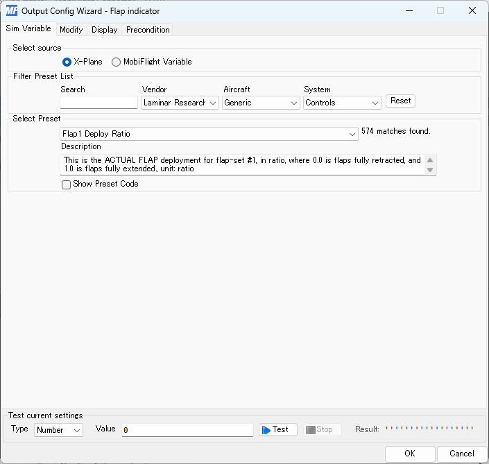
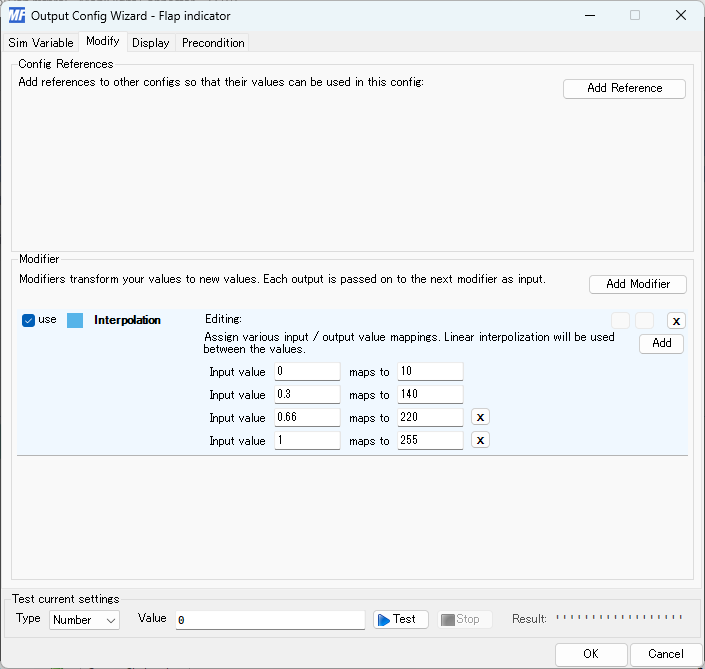
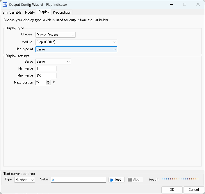
After some hustle, I successfully connect this input/output to flight simulator.
Problem I had.
I wired as active high on previous design but Mobiflight uses active low according to their document. So I changed wiring for switch.
Checklist
- Linked to the group assignment page.
- Documented how you determined power consumption of an output device with your group.
- Documented what you learned from interfacing output device(s) to microcontroller and controlling the device(s).
- Linked to the board you made in a previous assignment or documented your design and fabrication process if you made a new board.
- Explained how your code works.
- Explained any problems you encountered and how you fixed them.
- Included original source code and any new design files.
- Included a ‘hero shot’ of your board.