Week03
Computer-controlled cutting
Assignment
Group assignment:
- Do your lab’s safety training
- Characterize your lasercutter’s focus, power, speed, rate, kerf, joint clearance and types.
- Document your work to the group work page and reflect on your individual page what you learned.
Individual assignments
- Design, lasercut, and document a parametric construction kit, accounting for the lasercutter kerf.
- Cut something on the vinyl cutter.
Group assignment
Our document for group assignment.
Safety training
What I learned through safety training are:
- Be aware of fire. Keep the laser cutter in sight while it’s active.
- In case of small fire, you can put out with blowing or wet rag.
- For serious fire, there are fire extinguisher next to lastercutter.
- By opening the lig, you can do emergency stop. Be careful opening the lid, flame get oxygen.
- When it is active, do not directly look at the laser light, it can damage your eyesight.
- Open the window to avoid toxic gas.
Kerf tester

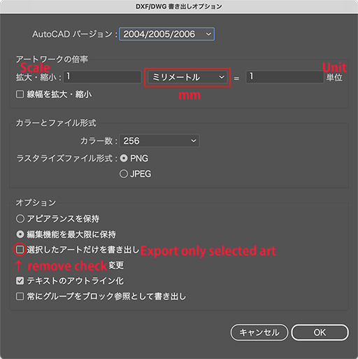
I drew kerf tester with Adobe Illustrator. When I export drawing in DXF format, you may need to choose some options. There were two things need to care. One is scale. I draw tester with “mm” scale so that I needed to specify units as “millimeter”. Second is uncheck “Export only selected art” option.
The original design file is: W3_Kerf_tester.ai
Press fitting test
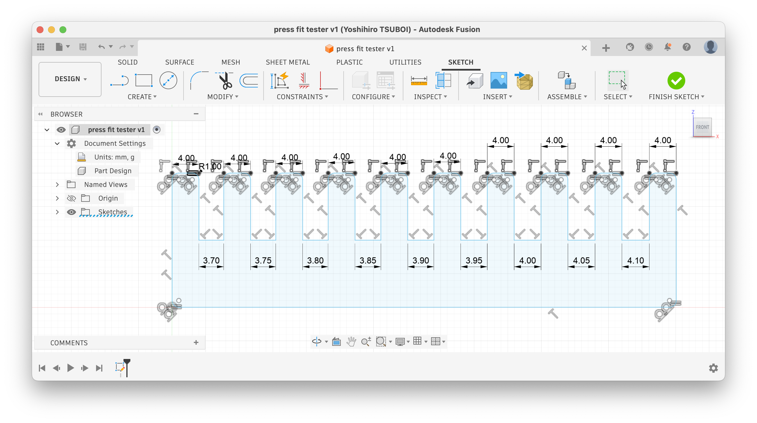
I draw test tool with Fusion. I thought about to draw it Illustrator but my friend said he’s using Fusion for this kind of purpose because Fusion has constrain function.
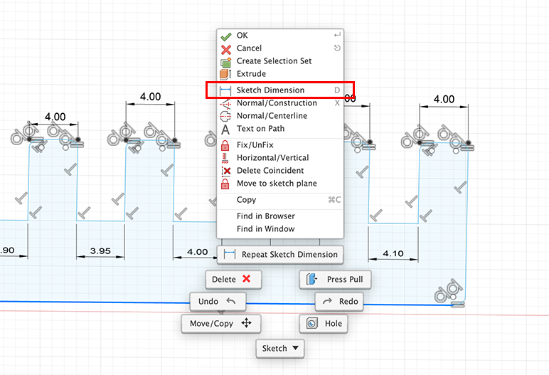
To add constraints on Fusion, just right click a target you want to set and choose “Sketch Dimension” from the menu. So that dimension line would be added and you can enter your desired dimension. That dimension is the constraint.
I draw press fitting tester with Fusion. To draw lasercut things with Fusion, start from “Create Sketch”. After finish drawing, click “FINISH SKETCH” button, and then [File]-[Export]. I choose DXF as the format.
Tip
To draw 2D DXF with Fusion, we need to draw X-Y axis (Top). I did it X-Z axis (Front) and got DXF that only have single line. 
The original design file is: W3_Press_fit_tester.f3d
Parametric construction
I planned to draw with Cuttle, but as I learnt constrain is useful and we can use parameter for constrain. So I did this with Autodesk Fusion.
On Sketch, I drew circle fifty millimeter in diameter at first, then drew a line for the center line of the circle. Set a option of line as construction.
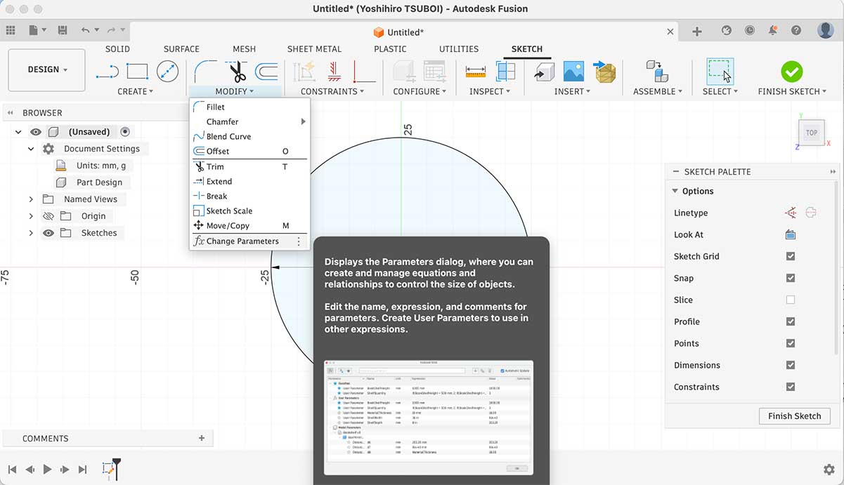
Parameter can be set “Change Parameter” under “Modify”.
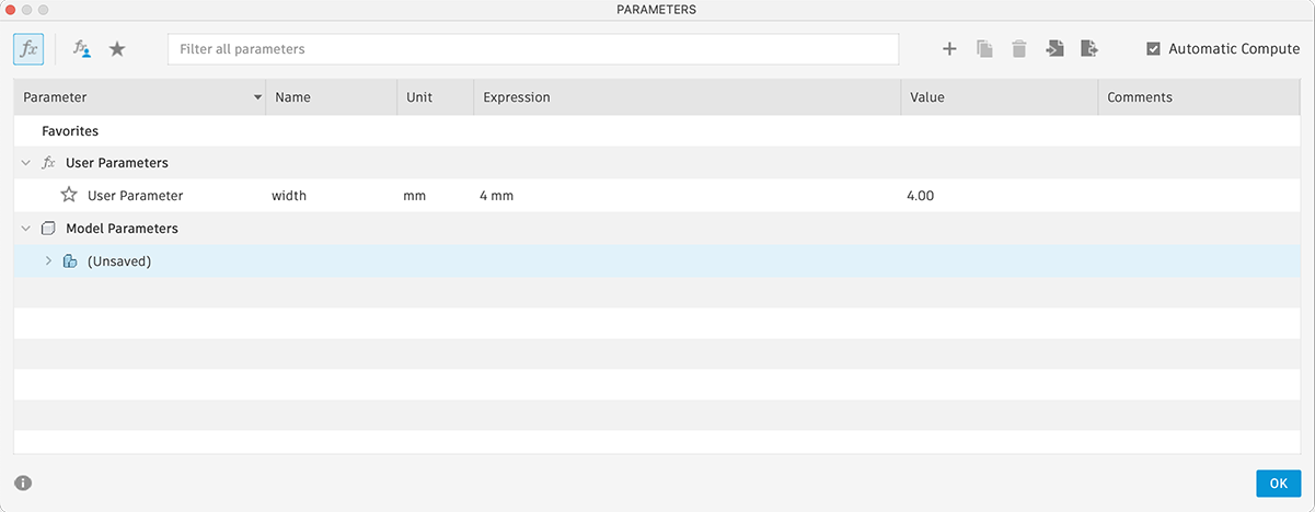
I sat parameter named “width” and temporary sat value as 4 mm.
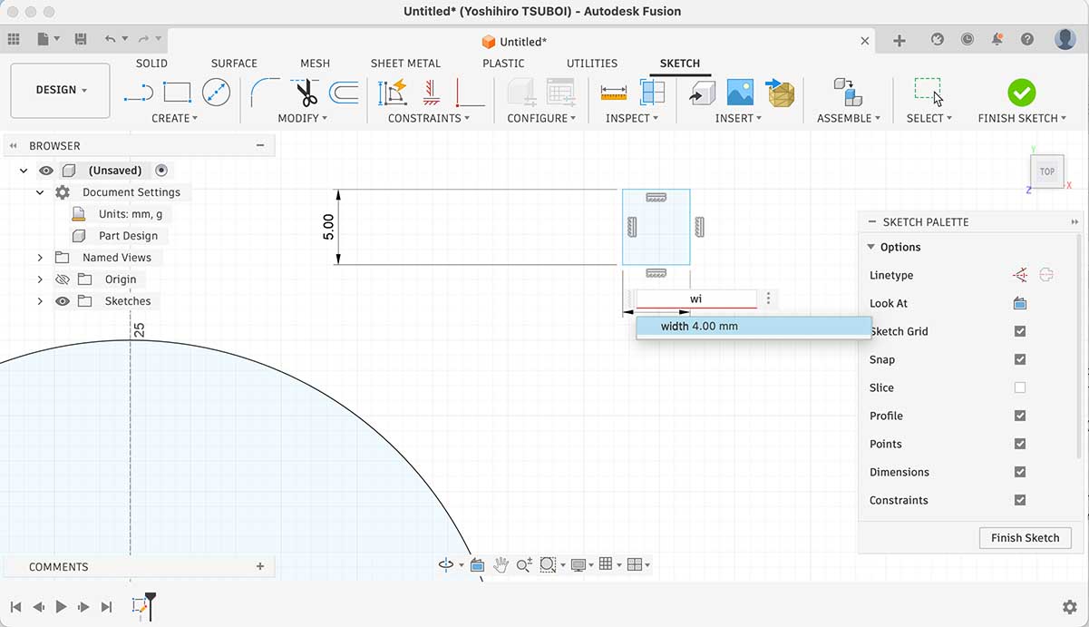
Draw a rectangle constrained as 5 mm depth and parameter “width” width. And constrained this rectangle to construction line by using “Midpoint”. To move the rectangle to the edge of circle, I constrained by using “Tangent”.
Suggestion from global instructor Iván
If you change the material (e.g. thickness) your parametric design would not work, that is why I would recommend to define at least two parameters to define the width of the slot: material thickness and kerf.
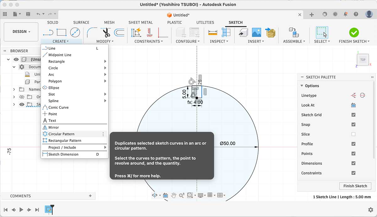
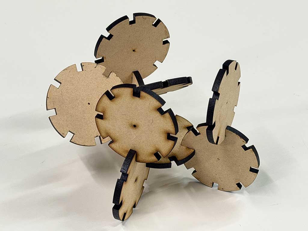
At last, I multiplied that rectangular slot by using “Circular Pattern” under “Create”.
Through the group assignment, I got “3.85 mm” is the dimension that fit to this MDF. So I changed the value of “width” parameter and lasercut.
The original design file is: W3_Parametric_Construction_Kit.f3d
Cut something on the vinyl cutter
I exported FabLab Nagoya logo in DXF format. Here is the file: W3_Fablab_nagoya_line.dxf
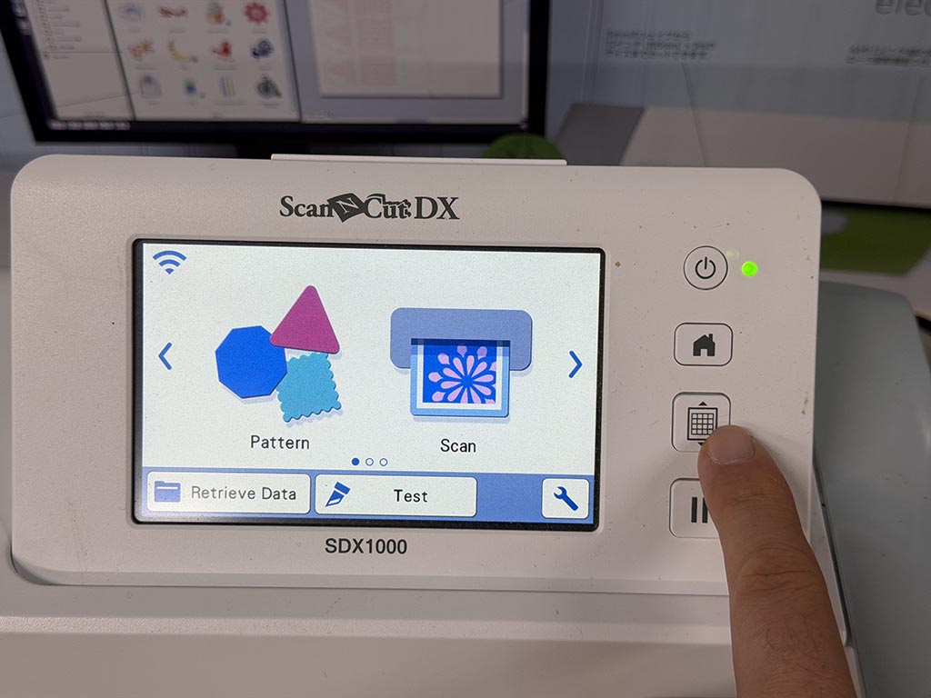
A vinyl cutter in our lab is Brother SDX1000 (Japanese oage, I couldn’t find this model on their US web). We need to use it’s application named “Brother CanvasWorkspace” to use this cutter.
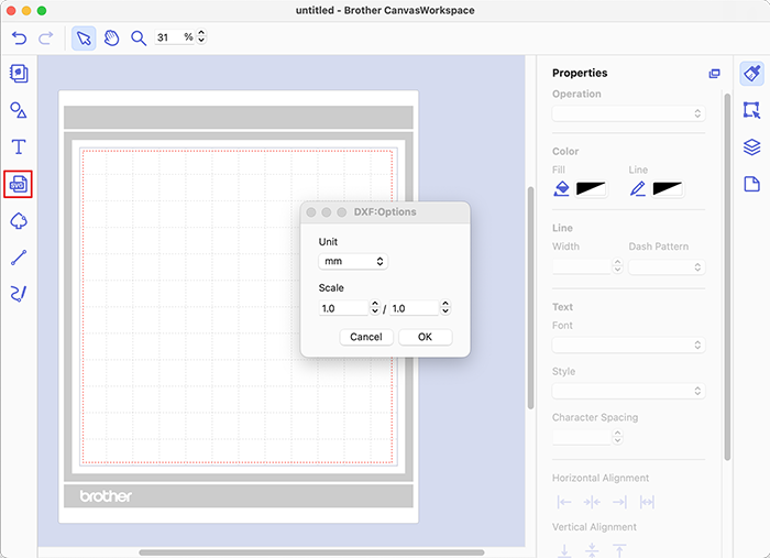
To import DXF, click SVG icons in red square, then choose DXF file and choose units for scale. When you finish layout, you need to export FCM file that the cutter can read. Exporting is in [File]-[Export/Transfer FCM File…]. I simple choose “Export FCM File” and copied exported file into thumb drive.
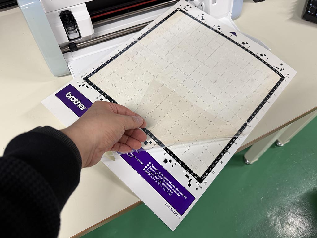
To set vinyl sticker sheet on cutter, we need to use mat. There are a protector sheet on mat, so we need to remove it at first. DO NOT THROUGH AWAY THE SHEET! We use mat repeatly, so you need to put back the protector sheet.
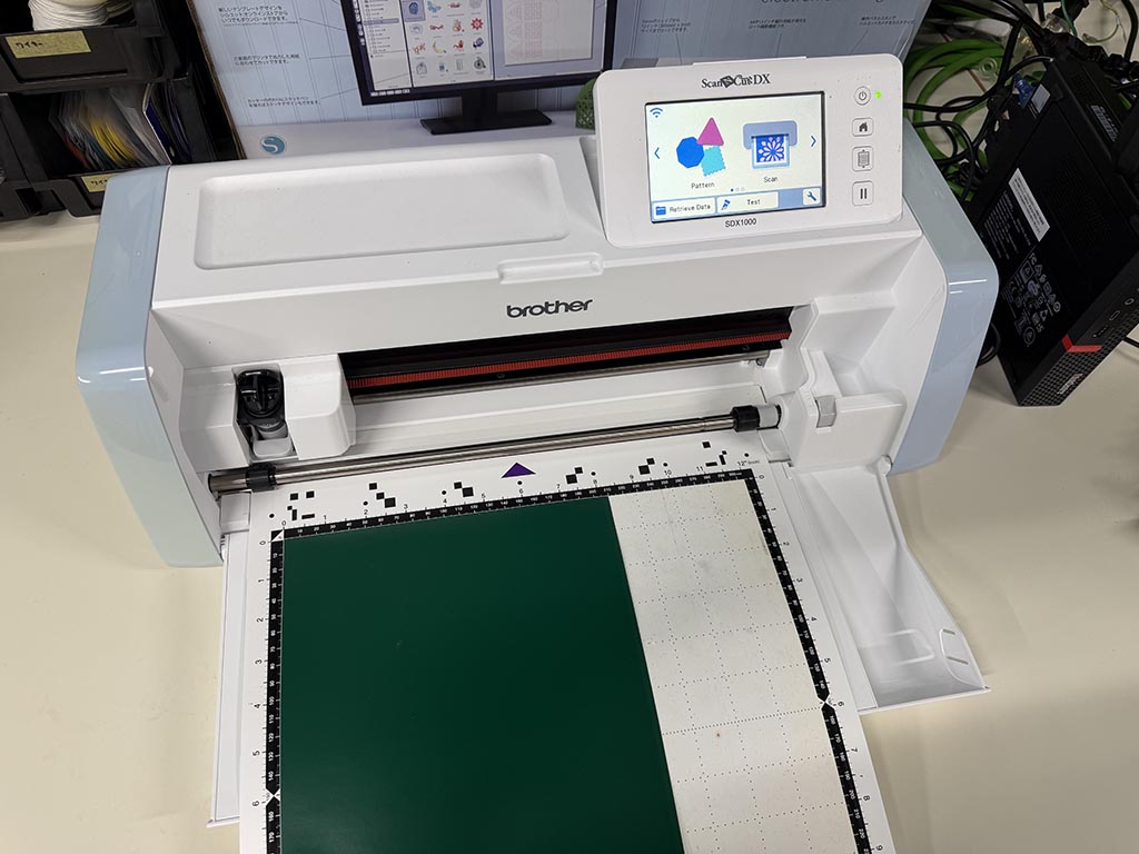
Since the mat is weak adhesive, you can paste material on the mat. Up left corner is the origin, so set the material left up corner as on the picture. And then, set the mat on the slot of the cutter.
By pressing feed button, your material will be loaded to the cutter with the mat.
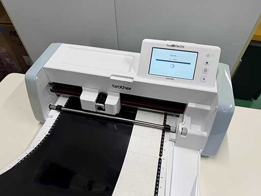
Then plug that thumb drive to SDX1000, and start cutting. I used initially bundled blade that support automatic adjustment, probably MPN CADXBLD1. SDX1000 doesn’t require blade adjustment.
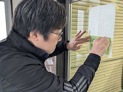
Since I wanted to paste it on the glass of entry door, I put printed paper backside to see the layout. I know there are application sheet but I prefered to use PE coated cloth tape because it can be cut by my hand. and tape has enough width to cover logo text.
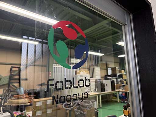
Done. Can this picture be a hero shot?
The original design file is: W3_Fablab_Nagoya_line.ai
Checklist
- Linked to the group assignment page.
- Reflected on your individual page what you learned of your labs safety training - here
- Explained how you created your parametric design. - here
- Documented how you made your press-fit construction kit. - here
- Documented how you made something with the vinyl cutter. - here
- Included your original design files.
- Included hero shots of your results.