14. Moulding and Casting
Assignments and Assessment this week
Group assignment
- Review the safety data sheets for each of your molding and casting materials
- Make and compare test casts with each of them
- Compare printing vs milling molds
Individual assignment
- Design a mold around the process you’ll be using, produce it with a smooth surface finish that does not show the production process toolpath, and use it to cast parts.
Learning outcomes
- Design appropriate objects within the limitations of your process
- Demonstrate workflows used in mold design, construction and casting
Have you answered these questions?
- Linked to the group assignment page and reflected on your individual page what you have learned
- Reviewed the safety data sheets for each of your molding and casting materials, then made and compared test casts with each of them
- Documented how you designed and created your 3D mold, including machine settings
- Ensured your mold has smooth surface finish, that does not show the production process (by postprocessing if necessary)
- Shown how you safely made your mold and cast the parts
- Described problems and how you fixed them
- Included your design files and ‘hero shot’ of the mold and the final object
Group Assignment
Here is a group assignment page
Research
This week I learned about how to mass-produce parts by making molds. The process involves creating a prototype with wax and then making a mold with silicone. If you want to use a material other than silicone, you pour the desired material into the silicone mold to create an identical replica.
In my hometown, there was a factory of CASTEM, a company famous for lost wax casting. When I visited as a student, they were using a very similar method to create shapes and mass-produce metal parts.
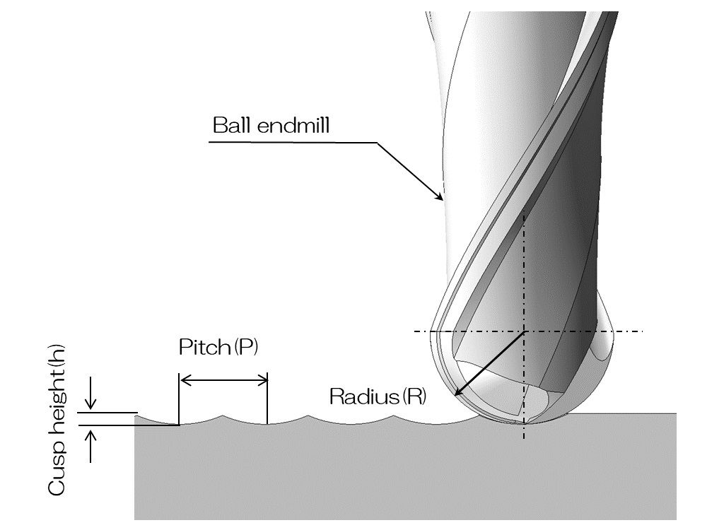
Ball End Milling: Uncut Surface
Finishing with a ball end mill can smooth the surface. However, uncut material inevitably remains due to the toolpath pitch during machining. This height of the cut edge is called the cusp height (also known as scallop height), and it can be calculated. The formula is this:
- h : Cusp height
- R : Tool Radius
- p : Tool path pitch
However, since the calculation is difficult, when the cusp height is sufficiently smaller than the tool radius ,
it can be approximated as follows.
A cusp height of 0.01 mm or less is considered ideal, but in this case, since the cutting time would be long, we set the target surface roughness value to 0.1 mm. In reality, a very nice mirror finish can be obtained with polishing if the cusp height is 0.2 mm or less.
 by Ogawa-tech
Wax Molding
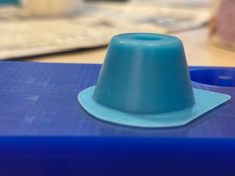
Creating a master mold by carving wax. The object I want to create this time is the rubber feet of the measuring machine for the final project, and since I want to make it out of silicone, I decided to create a female mold out of wax and pour silicone into it.
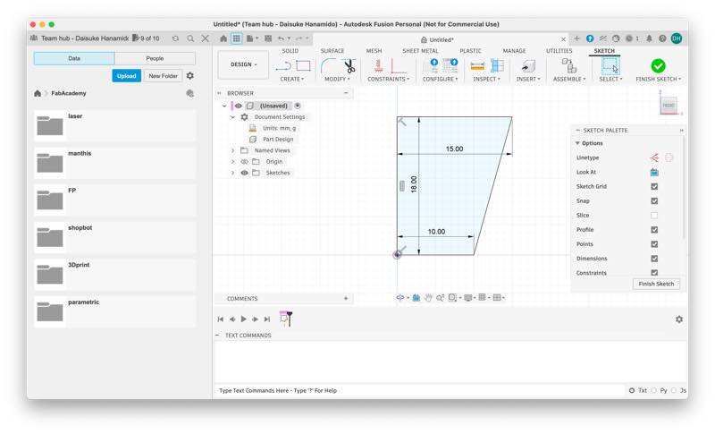
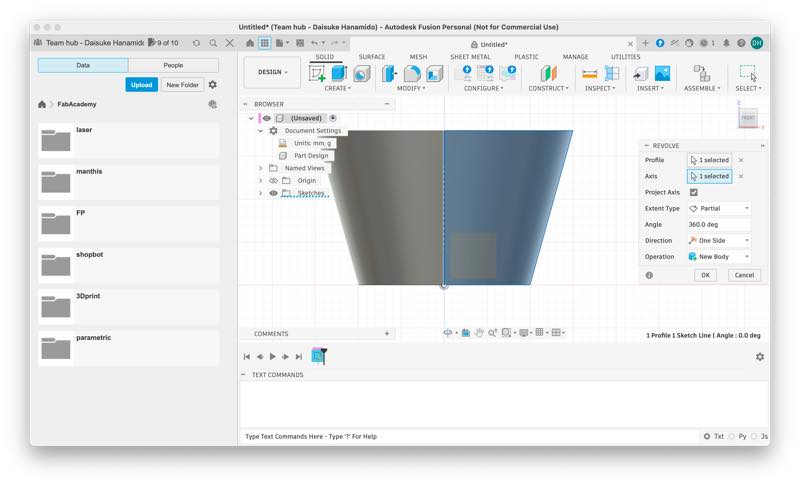
Modeling the prototype in Fusion. I created a shape like the ice cream bar “Pino” and added fillets to the parts that will come into contact with the ground.
I drilled a hole in the center for an M5 screw so that it could be attached with a screw.
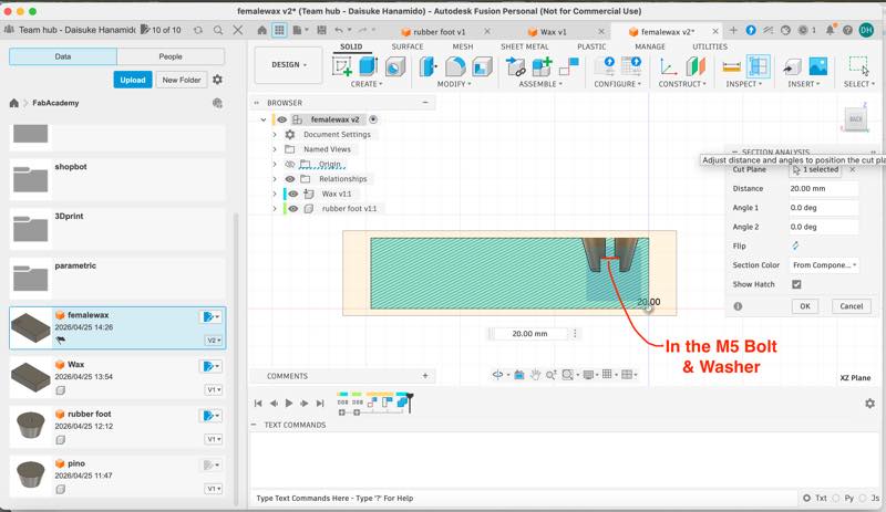
Measuring and modeling the wax.
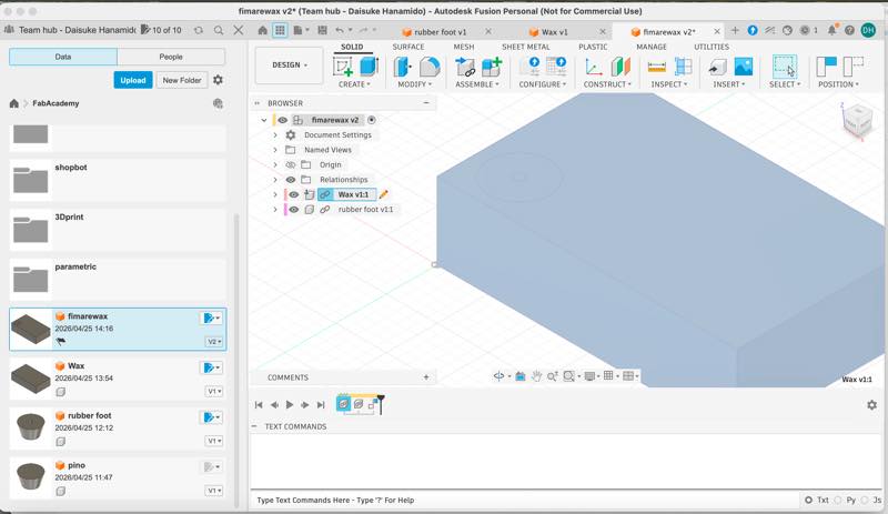
I combined two of these components and drilled a hole in the wax for inserting the casting material.
At this point, I couldn’t process the model without disconnecting the component links.
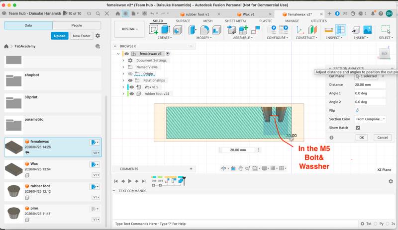
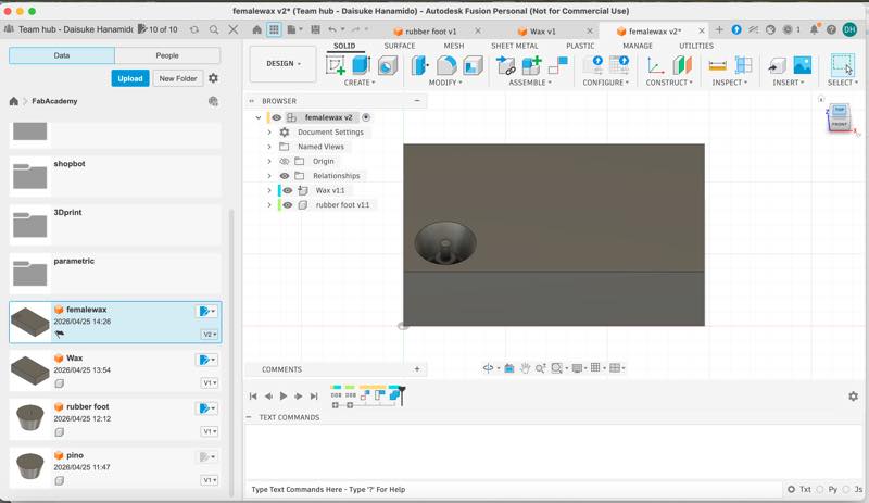
Completed female mold

Fusion Manufacture
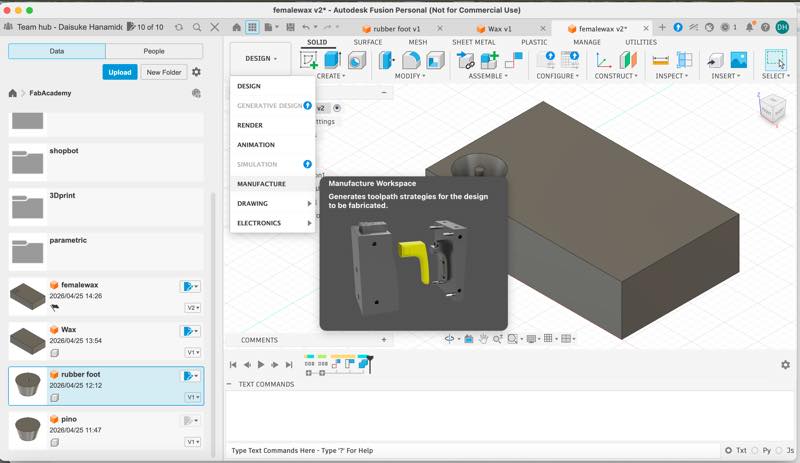
From here, we will generate toolpaths for machining using the SRM-20 to create this wax mold.
While we usually use MODELA Player 4. in Kamakura, I decided to use Fusion Manufacture to generate toolpaths because I was more familiar with Fusion CAM.
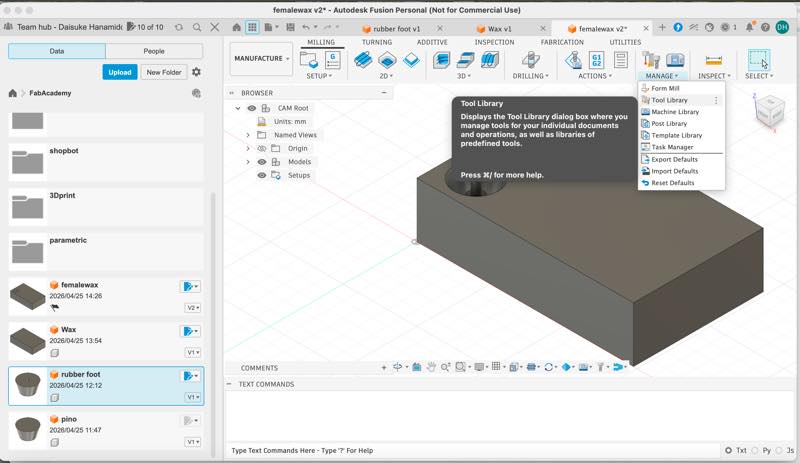
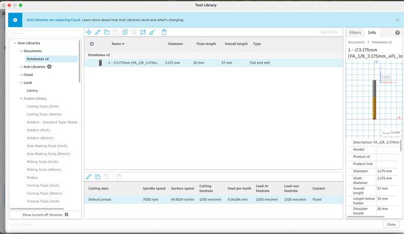
First, I created the data for the end mills.
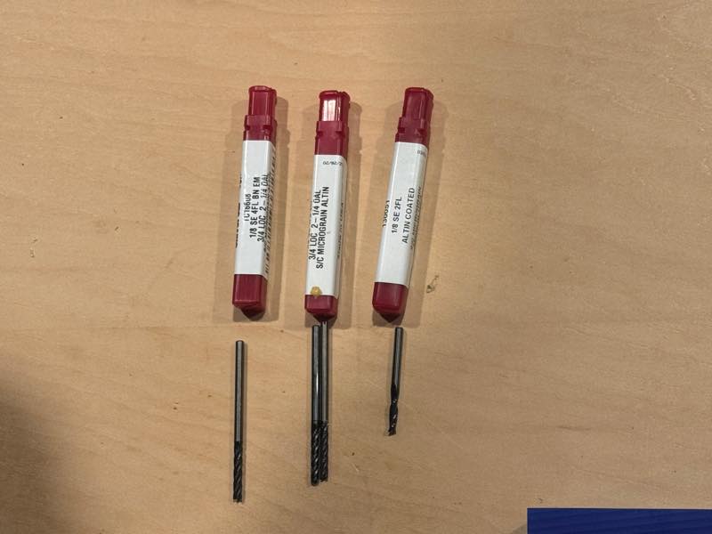
1/8 (3.175mm) 4-flute long-neck square end mill,
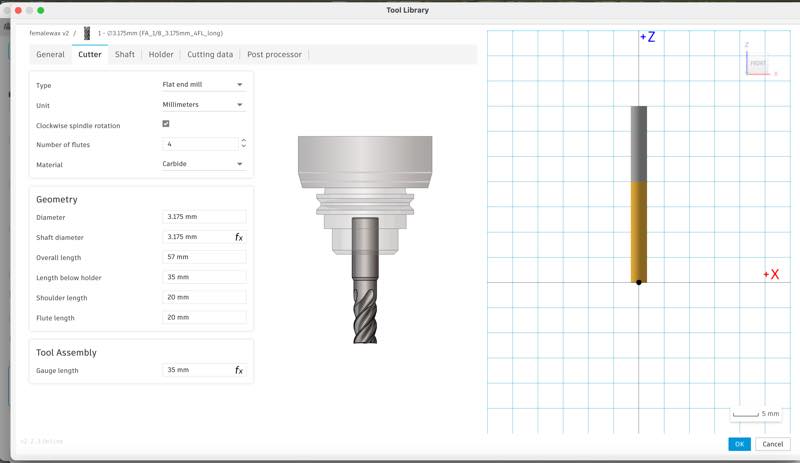
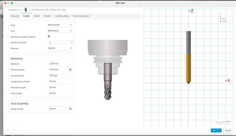
1/8 (3.175mm) 4-flute long-neck ball end mill
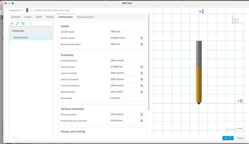
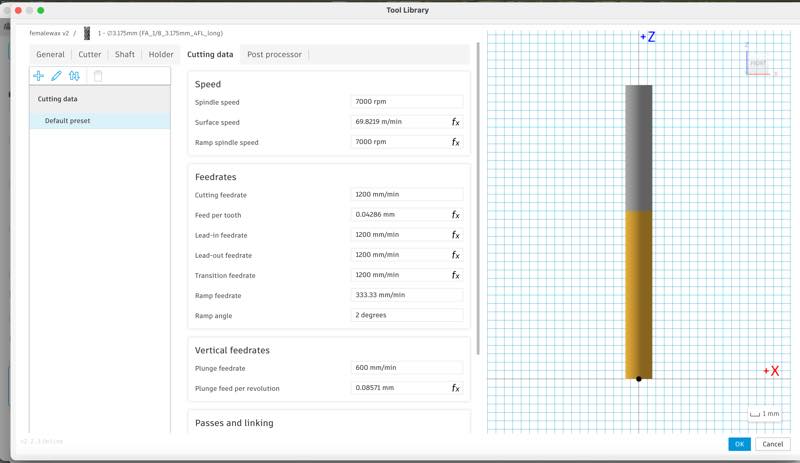
The necessary settings here are the machine’s rotation speed and the appropriate feed rate. Looking at Roland’s instructions, I found it was 7000 rpm, so I was able to set it immediately.
However, the cutting speed (feed rate) cannot be calculated, so I decided to reuse the value from MODELA Player 4., which had been working without problems.
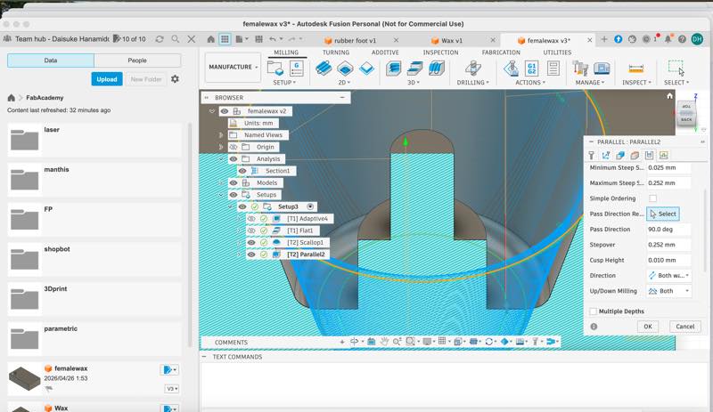
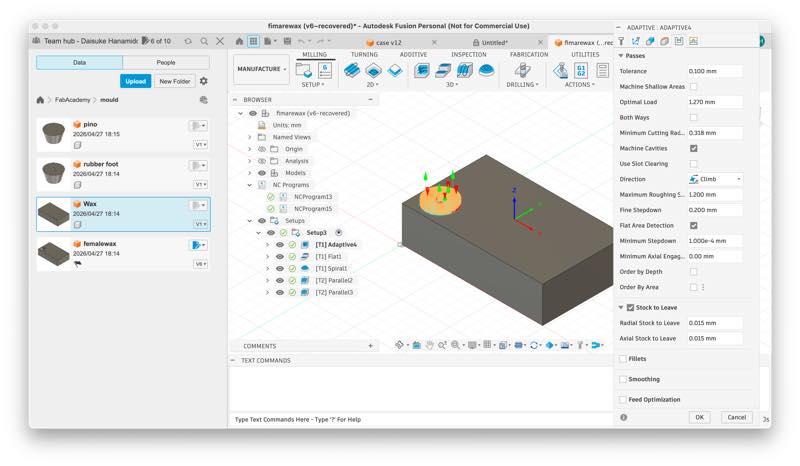
Then, I generated the cutting paths using these mills. Various path generation methods are available for both 2D and 3D cutting paths. This time, I used Adaptive Clearing for rough cutting, setting it to leave 0.015mm of material uncut. Then, the fillet sections that could not be machined with rough cutting were processed using the spiral tool, and the central cylinder was finished with flat cutting. Finally, the cutting tool was changed to a ball end tool, and the curved sections were finished by machining twice with parallel paths that intersected at a 90-degree angle.
The process is as follows: - 1. Select the path you want to create.
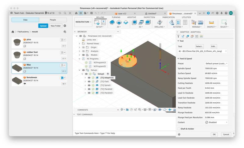
- 2. Choose the end mill to use.
- 3. Confirm the set Feed and Speed.
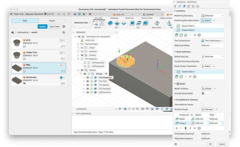
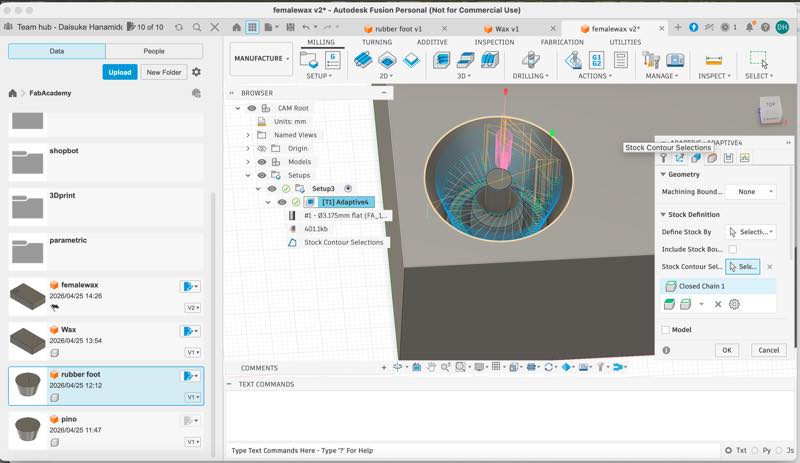
- 4. Select the parts you want to machine and the parts you don’t want to machine in Geometry.
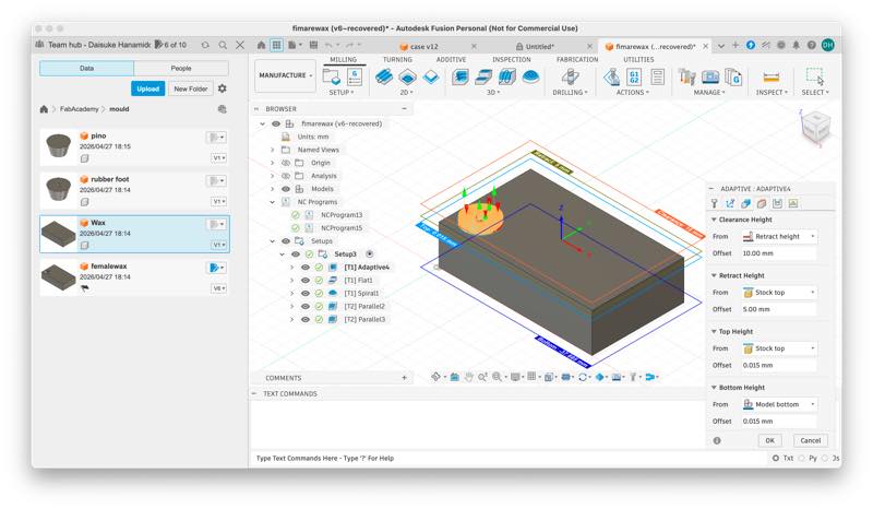
- 5. Set the height the tool moves in Heights (it will move by default, but if the material is large and the upward movement range is limited, review the settings).
- 6. Set the up-cut, down-cut, tolerance for the depth cut in one pass in the Z direction, and the amount of material left over during roughing in Passes.
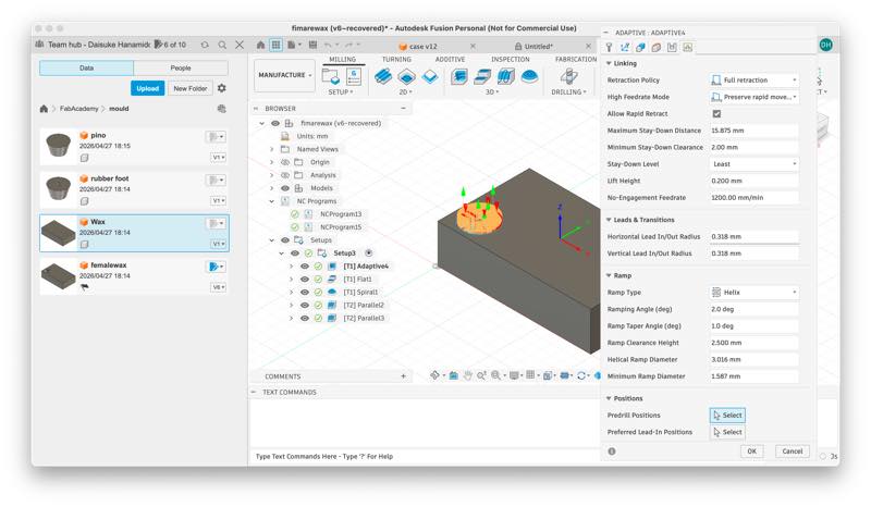
- 7. Readjust the Linking settings if you want to shorten the time (default is OK if it doesn’t matter).
This allows you to easily generate a series of cutting paths.
Especially once you’ve set it up initially, you can generate toolpaths freely by just adjusting 1, 4, and 6. In practice, you can generate a temporary path by simply selecting the cutting method and mill and the area you want to machine, and then refine the settings from there.
The settings up to this point are similar regardless of which CNC you use.
Incidentally, using Simulate in Actions will simulate the toolpath for the currently selected machining process and allow you to check the machining time. At this point, the areas highlighted in red indicate machining errors (such as the mill contacting an area it shouldn’t be machining, or the mill’s machining conditions being deviated). Therefore, you need to regenerate the cutting path with different conditions.
(Fusion may freeze due to heavy use of graphics functions, so it’s a good idea to save your work before simulating.)
Also, the size of the material to be machined (stock) can be changed from the Stock section in Setup, and the workpiece origin set here will be carried over.
3D Model&cuterpass
Postprocesser
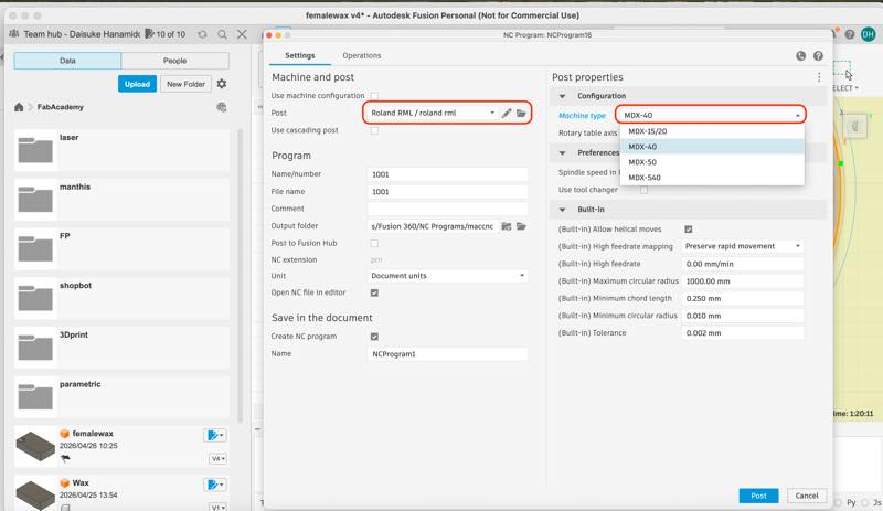
From here, the machining program for SRM-20 machining is output. The post-processor is necessary to change the generated program, and it differs depending on the machine. By changing this selection, you can change whether the machining is done with the SRM-20 or ShopBot.
Selecting Roland RML from the Fusion library and saving it to the cloud will allow you to retrieve it from the cloud next time.
By selecting Roland RML in Post and setting the Machine type to MDX40, you can generate a program .prn file that runs on the SRM-20.
Load the generated .prn file into Vpanel.
SRM-20 Setup
Setting and Operation Check
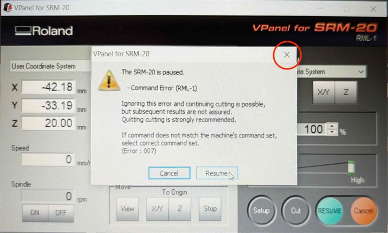
When I tried to clean the chips and stopped the machine using the stop button, an error occurred and it wouldn’t resume. While it’s not ideal to stop it like this, I was able to resume from where I left off by opening the machine lid and stopping it that way. Later, I found that Greg Buckland 2018 had posted a solution under the heading
It seems that closing the pop-up error window with the “X” button will get it working again.
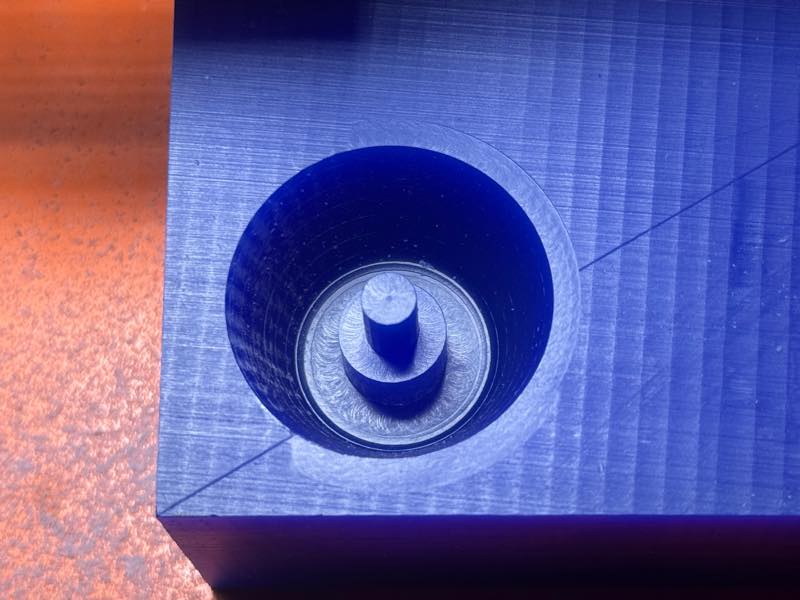
finish milling
Completed Wax Mold
Casting
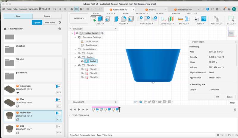
How to calculate volume in Fusion
Open the original component design from which you cut the wax. Right-click on the Body and click Properties. You can then see the volume: Volume 8021.424 mm^3.
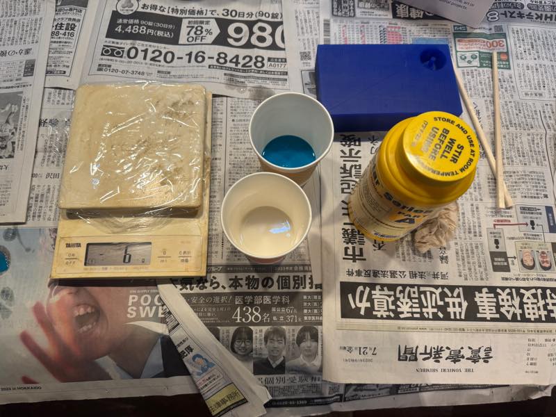
The casting material was silicone. Weighed, mixed, and poured into the mold.
Hardened and removed from the mold.
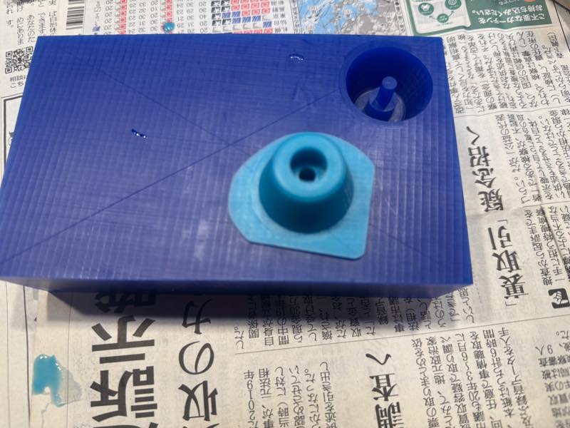
Completed
References links
-
Hashim Al Sakkaf 2017
-
Greg Buckland 2018
I’ll give a brief explanation of Fusion 360’s CAM features. by Something Technical Research Institute
Design Files
FusionFile1
MillingprogramFile2
Wax STL File3