Final Project
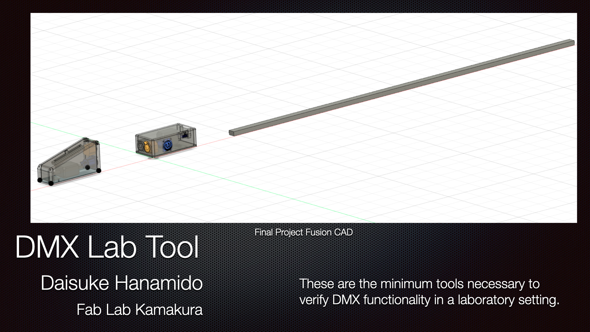
DMX Lab Tool
This is a set of modules for easily testing DMX signals.
The first device outputs DMX according to the movement of the fader.
The second device displays the current DMX value on a monitor in real time.
The third device controls the RGB brightness of NeoPixel LEDs with the DMX value.
These are connected with a 5-pin DMX signal cable.
Details of the production process can be found on the tracking page.
Final project summary slide
Final project video clip
Questions and Answers
What does it do?
This is a set of modules for easily testing DMX signals.
DMX signals are output in accordance with the fader movement, displaying the current DMX value on the monitor, and controlling the RGB brightness of the NeoPixel LEDs with the DMX value.
Who has done what before?
 by SOUND HOUSE
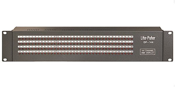
Similar displays have existed before, such as the Lite putter DP-144, but they were mainly simple 3mm bullet-shaped LEDs that blinked or required connecting to a computer, and weren’t very user-friendly.
What did you design?
I designed a DMX test and monitoring system consisting of three interconnected devices, including their custom printed circuit boards (PCBs) and enclosures:
-
DMX output control device: A master controller equipped with a physical fader to generate and send test DMX512 signals.
-
DMX monitoring device: A single-universe tester capable of receiving a DMX universe, parsing the data using an ESP32-WROOM module, and visualizing the channel status on a salvaged toy LCD screen.
-
DMX input NeoPixel LED: A receiver node that decodes incoming DMX signals and maps the channel values onto a NeoPixel addressable LED strip.
What sources did you use?
FabAcademy class page, Fab Community, Google Search, YouTube tutorials, ChatGPT, and friendly instructors! And I also received various advice from my mentor at the company, Toshihiro Hosoda.
What materials and components were used?
Here the BOM
Bill of Materials(BOM)
DMX output control device - BOM
| Component | Material | Description | Qty | Vender | Cost |
|---|---|---|---|---|---|
| PCB | Seeed Studio XIAO RP2040 | Main MCU assembly for control and signal generation | 1 | DigiKey / Fab Lab Inventory | Approx. ¥1,200 ($8.00) |
| PCB | MAX485 Transceiver IC | IC component to convert MCU UART to DMX signal | 1 | Akizuki Denshi / Fab Lab | Approx. ¥200 ($1.30) |
| PCB | Slide Fader | Assembled analog fader component for level input | 1 | Fab Lab Inventory | Approx. ¥300 ($2.00) |
| PCB | 5-pin Connector (Female) | Pre-fabricated connector component for DMX output | 1 | Sound House / Retail | Approx. ¥400 ($2.60) |
| PCB | SMD Passive Materials | Raw resistors, capacitors, and resistors for the PCB assembly | 1 | Fab Lab Inventory | Included in lab fee |
| PCB | FR-1 Single-sided Board | Raw copper-clad laminate for milling the PCB | 1 | Fab Lab Inventory | Included in lab fee |
| Case | 3D Printing Filament (PLA/PETG) | Raw filament material for printing the enclosure | 1 | Fab Lab Inventory | Approx. ¥600 ($4.00) |
| Case | MDF Board (2.5 mm) | Raw sheet material for laser cutting the under panel | 1 | Fab Lab Inventory | Included in lab fee |
DMX monitoring device - BOM
| Component | Material | Description | Qty | Vender | Cost |
|---|---|---|---|---|---|
| PCB | Freenove ESP32-Wroom | Assembled Wi-Fi/Bluetooth MCU core module | 1 | DigiKey / Fab Lab Inventory | Approx. ¥700 ($4.50) |
| PCB | MAX485 Transceiver IC | IC component for single-universe receiver line | 1 | Akizuki Denshi / Fab Lab | Approx. ¥200 ($1.30) |
| PCB | LCD Monitor Display | Complete display module salvaged from an old toy | 1 | Witch or Iris elongated LCD Display | ¥10000 (discount take off) |
| PCB | 5-pin Connector (Male) | Pre-fabricated connector component for DMX input | 1 | Sound House / Retail | Approx. ¥400 ($2.60) |
| PCB | 5-pin Connector (Female) | Pre-fabricated connector component for DMX output | 1 | Sound House / Retail | Approx. ¥400 ($2.60) |
| PCB | Passive Materials | Raw electronic elements (resistors, caps, pins) for assembly | 1 | Fab Lab Inventory | Included in lab fee |
| PCB | FR-1 Single-sided Board | Raw copper plate material for milling the adapter PCB | 1 | Fab Lab Inventory | Included in lab fee |
| Case | MDF Board (2.5 mm) | Raw sheet material for laser cutting the structural box | 1 | Fab Lab Inventory | Approx. ¥300 ($2.00) |
| Case | Black Spray Paint | Finishing material for painting the MDF exterior | 1 | Retail | Approx. ¥200 ($1.30) |
| Case | Molding & Casting Resin / Silicone | Liquid chemical materials for casting the support feet | 1 | Fab Lab Inventory | Approx. ¥600 ($4.00) |
| Case | 3D Printing Filament (PLA/PETG) | Raw filament material for small assembly joints | 1 | Fab Lab Inventory | Approx. ¥200 ($1.30) |
DMX input NeoPixel LED - BOM
| Component | Material | Description | Qty | Vender | Cost |
|---|---|---|---|---|---|
| PCB | Seeed Studio XIAO RP2040 | Main MCU assembly for parsing and | 1 | DigiKey / Fab Lab Inventory | Approx. ¥1,200 ($8.00) |
| PCB | MAX485 Transceiver IC | IC component to receive differential DMX signals | 1 | Akizuki Denshi / Fab Lab | Approx. ¥200 ($1.30) |
| LED | NeoPixel Addressable LED Strip | Assembled LED strip component for visual output | 1 | Amazon / Fab Lab Inventory | Approx. ¥1,200 ($8.00) |
| PCB | 5-pin Connector (Male) | Pre-fabricated connector component for | 1 | Sound House / Retail | Approx. ¥400 ($2.60) |
| PCB | 5-pin Connector (Female) | Pre-fabricated connector component for | 1 | Sound House / Retail | Approx. ¥400 ($2.60) |
| PCB | SMD Passive Materials | Raw electronic components for the LED decoder | 1 | Fab Lab Inventory | Included in lab fee |
| PCB | FR-1 Single-sided Board | Raw fiberglass board material for milling the PCB | 1 | Fab Lab Inventory | Included in lab fee |
| Case | 3D Printing Filament (Diffusive PLA) | Raw filament material for fabricating the | 1 | Fab Lab Inventory | Approx. ¥500 ($3.30) |
Where did they come from?
Look at the BOM
How much did they cost?
Look at the BOM
What parts and systems were made?
-
DMX output control device
-
Custom Main Controller PCB: A custom-milled circuit board fabricated in-house using an FR-1 substrate, integrating a Seeed Studio XIAO microcontroller with a MAX485 transceiver IC to convert UART signals into differential DMX512 signals.
-
DMX Generation System (Firmware): Embedded software logic that handles the analog fader input and accurately packages it into the DMX512 protocol, including precise BREAK and MAB timing generation.
-
3D-Printed Enclosure: A custom-designed handheld shell with precise cutouts optimized for user accessibility to the fader control and the XLR interface.
-
-
DMX monitoring device
-
Custom Receiver and Adapter PCB: An in-house fabricated FR-1 breakout and signal adaptation board that routes incoming DMX signals safely into an ESP32-WROOM module.
-
1-Universe Parsing and Rendering Engine (Software System): Embedded software for the ESP32-WROOM that intercepts a single universe of DMX data stream in real time and handles visual output for a salvaged display.
- Hybrid Structural Enclosure: A painted black enclosure constructed from laser-cut MDF panels, interconnected using custom 3D-printed joints.
- Molded Support Feet: Dedicated stabilization feet produced using molding and casting fabrication techniques.
-
-
DMX input NeoPixel LED
-
Custom LED Decoder PCB: A dedicated receiver board combining a MAX485 line receiver with a high-current 5V power routing network to safely drive the addressable LED strip without damaging the microcontroller.
-
DMX-to-LED Mapping Logic (Software System): A firmware system that listens to assigned DMX start addresses, extracts the corresponding data slots (e.g., Ch1=R, Ch2=G, Ch3=B), and translates them into a single-wire NeoPixel data protocol in real time.
-
LED Diffuser & Holder Enclosure: A specialized 3D-printed mounting frame structured to safely hold the LED strip while diffusing the point-source light evenly.
-
What processes were used?
-
2D Design
Monitor Case, bottom cover of each devices.
-
3D Design
Slide fader case Neo pixel controller case
-
Additive process
3D printing of Slide fader and Neo pixel controller case
-
Subtractive process
Molding and casting of silicon foot parts Laser cutting of Monitor case
-
Electronics design and production
Two pcb with XIAO and a couple of pcb to connect output signal lines.
One pcb with ESP32 and LCD connection with DMX receiver of MAX485.
-
Embedded microcontroller design, interfacing and programming
Program to PCB with XIAO (slider input control by DMX to control Neo pixel on XIAO)
Program to PCB with ESP32 (Outputting a graph of DMX signals to the LCD)
-
System integration and packaging
The wiring has been converted to connectors and bundled with cable ties. A shake test was performed on all devices to confirm that they were functioning correctly after the test.
What questions were answered?
It is possible to create changes in the DMX and visually observe the movement.
What worked? What didn’t?
-
What I accomplished:
I was able to monitor the movement of DMX signals. I created a control device that outputs DMX signals. I was able to create a device that operates using DMX signals.
-
What didn’t work out:
Many parts could not be implemented due to poor time management.
I attempted to create a monitoring device for 4 channels, but ran out of time and only managed to monitor 1 channel.
Since the control device only has one slide fader, it was only possible to control all 512 channels simultaneously.
The DMX-operated device lacks a channel setting section, so channel changes cannot be made without rewriting the program.
How was it evaluated?
It will be perfect if all devices are connected and the changes follow the fader movements.
What are the implications?
This project will make it easy to create original DMX devices using digital fabrication.
To allow many people to use this project, I have decided to release this work under CC0 1.0 Universal![]()
![]() .
.
License
Creative Commons zero
![]()
This work is marked CC0 1.0 Universal![]()
![]()
Design Files
1. DMX output control device
DMX 5-pin female board kicad File
DMX 5-pin female board Gerber File
2. DMX monitoring device
Freenove ESP32-WROOM32E Support
Freenove ESP32-WROOM32E Boaed Pinout.pdf File
Librizer Freenove ESP32-WROOM32E kicad Footprint & Symbol File
DMX 5-pin female board kicad File
DMX 5-pin female board Gerber File
DMX 5-pin male board kicad File
DMX 5-pin male board Gerber File
Rubber foot Mould SRM20 Milling program File
3. DMX input NeoPixel LED
DMX 5-pin female board kicad File
DMX 5-pin female board Gerber File
DMX 5-pin male board kicad File