3. Computer controlled cutting
Assignments and Assessment this week
Group assignment:
- Do your lab’s safety training
- Characterize your lasercutter’s focus, power, speed, rate, kerf, joint clearance and types.
- Document your work to the group work page and reflect on your individual page what you learned.
Individual assignments
-
Design, lasercut, and document a parametric construction kit, accounting for the lasercutter kerf.
-
extra credit: design it to be assembled in multiple ways
- extra credit: include elements that aren’t flat
- extra credit: engrave as well as cut
Learning outcomes
- Demonstrate and describe parametric 2D modelling processes.
- Identify and explain processes involved in using the laser cutter.
- Develop, evaluate and construct a parametric construction kit.
- Identify and explain processes involved in using the vinyl cutter.
Have you answered these questions?
- Linked to the group assignment page.
- Reflected on your individual page what you learned of your labs safety training Explained how you created your parametric design.
- Documented how you made your press-fit construction kit.
- Documented how you made something with the vinyl cutter.
- Included your original design files.
- Included hero shots of your results.
Group Assignment
Here is a group assignment page
Safety Training
The optimal parameters for the lab’s laser for the 3mm thick cardboard used in this project are summarized on the group assignment page below. This page also provides a brief summary of the details.
- Participants: Koshi Kato (2026)
Instructors:
-
Safety Training Instructor: Youka Watanabe (Lab Master)
-
Shoko Kudomi (2025)
- Maki Tanaka (2025)
- Kae Nagano (2019)
- Tsuchiya Yosuke (2019)
Laser cutting machine safety training and usage training
Things That Cannot Be Cut
Never cut materials that contain chlorine (such as vinyl chloride) as this will destroy the lens through a chemical reaction. Also, when processing mirrors, do not cut them unless safety measures against laser reflection have been taken.
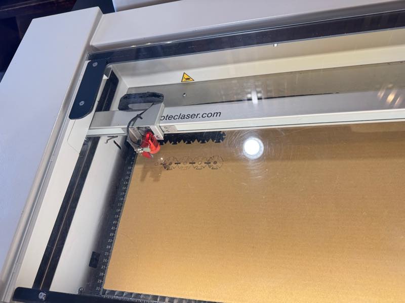
How to determine optimal parameters for processing materials
Here is vest parameters shot
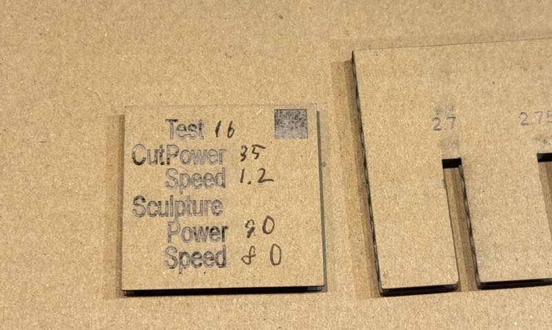
we chenge cutting speed and laser power. Our Best Setting for 3mm thickness Carton Board.
For Cutting
Power: 35
Speed: 1.2
For engraving
Power: 90
Speed: 80
Selecting the optimal width (kerf value) when creating a fit
The kerf value we used Kerf Check Parts Generator made by Daisuke Doyo (2018)
When the cardboard thickness was 3.0 mm, the base thickness was set to 3.0 mm and the pitch to 0.05 mm. Cutting data was generated by repeating a total of 11 thickness variations in the positive and negative directions.
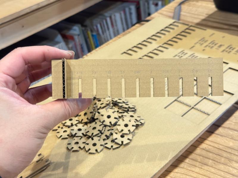
The best Slot width with was 2.7mm
What is Parametric Modeling?
This is a design method where numerical values are fixed. By writing the desired values in a spreadsheet (such as Excel) and importing it into CAD software, the model can adapt to changes in the object’s size during the design process.
Parametric Modeling in Fusion
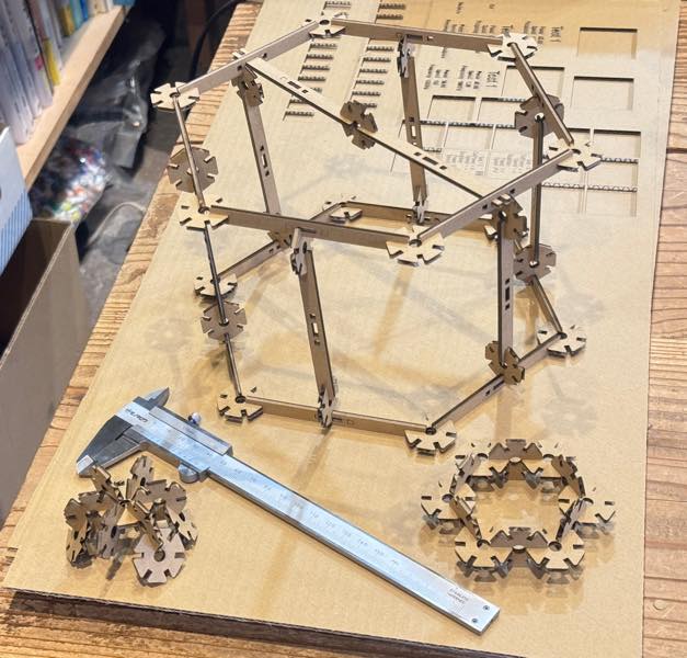
For this assignment, I designed a jointable object using parametric modeling. The shape was based on the “math counters” and “counting sticks” found in the “math sets” used in Japanese elementary schools.
After I made it, I realized that the toy blocks called Mega Bloks on Amazon were similar.

Math Marbles
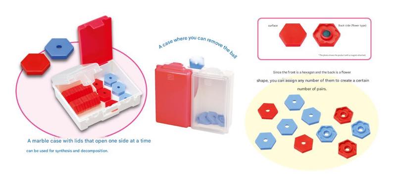
“Math Marbles,” a staple of math teaching materials, also known as “Sansu-Ohajiki” in Japanese, are small plastic discs used by elementary school students in Japan.
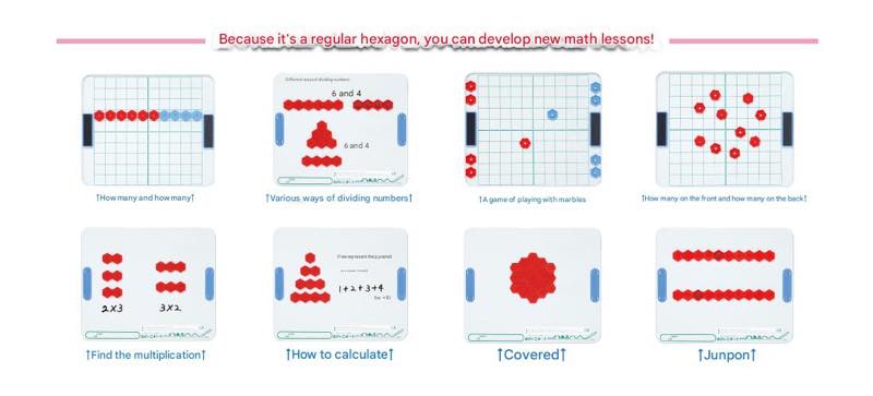
By counting these discs, children can visually understand numbers, and by practicing with their hands, they can learn the basics of addition and subtraction.
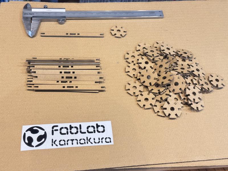
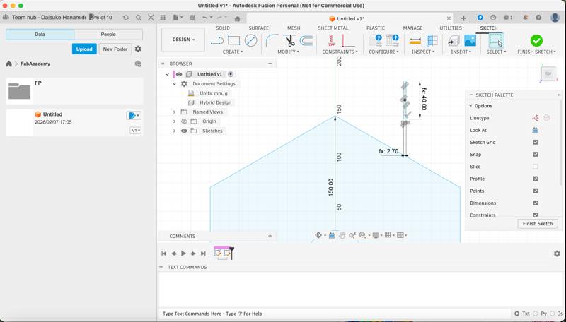
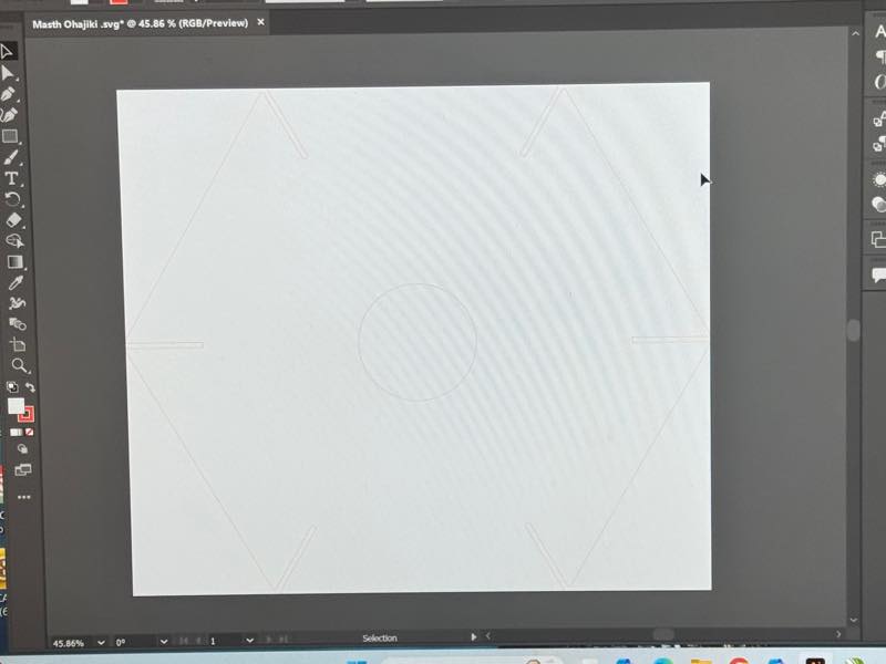
Modeling
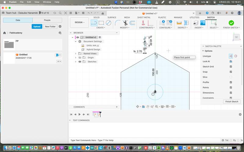
First, we model a hexagon.
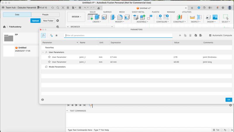
Then, we created the notches for joining using parameter trick modeling by specifying numerical values.
The 2.7mm set in joint_t is the best slot width when the parts are fitted together.
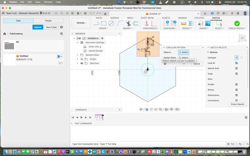
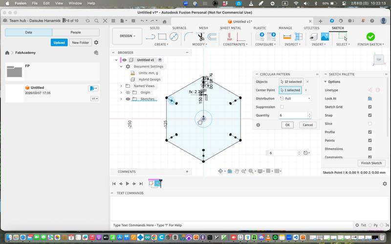
We then duplicated it six times using circular alignment, specifying the object to be duplicated and the rotation origin.
We extruded it to solidify it. We chamfered the entrance corners of the fitting parts. The previous version had a bevel (C) chamfer within the fillet, but the version was suddenly updated and the location changed, making it difficult to find immediately. A 45° chamfer was used to chamfer all the entry points where the plates fit.
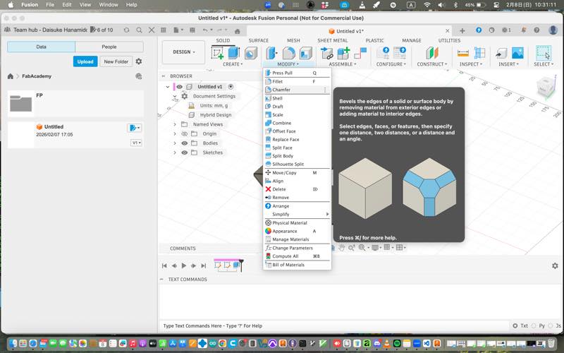
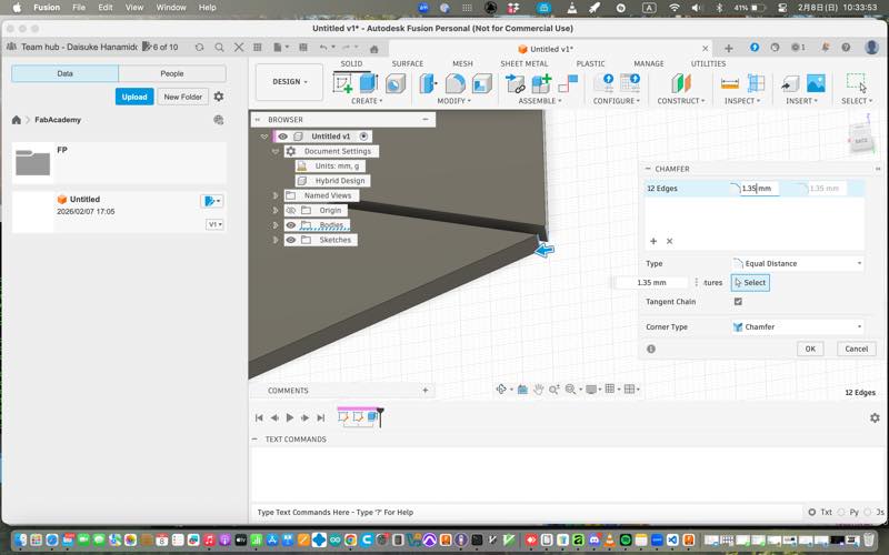
This allowed the joint to fit smoothly. The data is now complete.
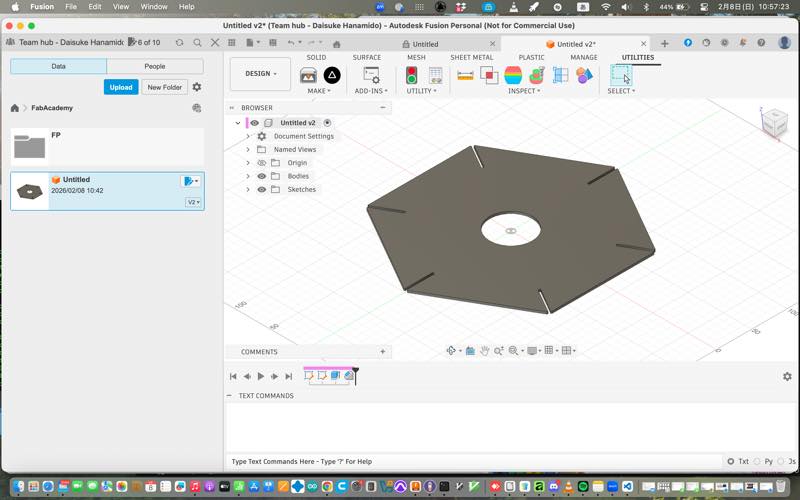

Masth Ohajiki.f3d 1
Machining Data Output
There are several methods for extracting data from Fusion for machining with a laser in Lab.
-
Extract g-code data with post-processing applied to match the machining equipment using Fusion CAM.
-
Create a drawing, export it as a .pdf, and import it into Torotec’s Ruby®. (Ruby® can read .ai, .pdf, .svg, and .dxf files; for engraving only, it can read .png, .jpg, .jpeg, and .bmp files.)
-
After importing the PDF into CorelDRAW, open Torotec’s JobControl® from the print menu. Alternatively, open JobControl® from vector software such as Adobe Illustrator, InkScape, or Affiliate.
-
This method involves installing the “Shaper Utilities” plugin in Fusion, opening the image in InkScape, editing it, and then launching JobControl® from the print menu for further processing.
Installing Shaper Utilities
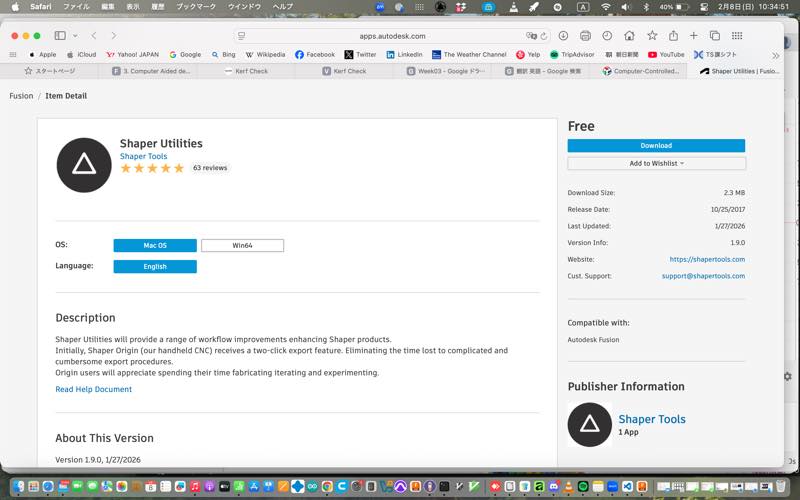
Shaper Utilities Download and install from this site, then restart Fusion.
How to Output as SVG
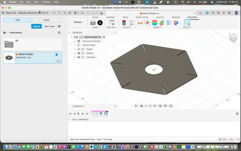
Open Utilities from the top menu in Fusion and click the Shaper Utilities icon. This will open Screenshots. Select the faces of the model you want to output as SVG and click OK. The .svg file will be output to the specified folder.
In Inkscape
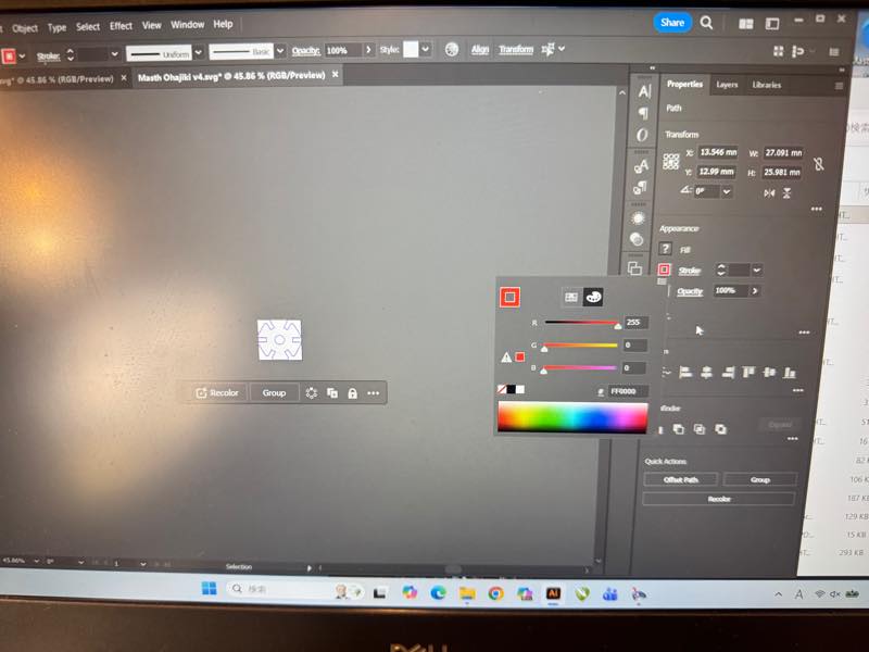
Import the output file. The image will have a black border and be filled with black. To make it suitable for laser cutting, remove the fill from the inside, change the color of the outer border (stroke) to red (R255G0B0), and set the line thickness to 0.001mm. If the line is too thin to see, turn on the “Visible Hairline” option in the View tab. Also, it’s best to use the same version of Inkscape on your computer as the version installed on the computer containing the laser controller to avoid errors. Furthermore, a common problem is that while the image appears red in Inkscape, nothing is displayed when imported into JobControl®.
In this case, possible causes include incorrect line thickness, increased color transparency, or the use of CMY instead of RGB for creating red. Furthermore, if data created in Inkscape doesn’t display correctly when opened in Illustrator or another version of Inkscape, check the color profile settings, as these may differ between the two applications. After setting the border to R255 and width 0.01mm, transfer the data to the PC connected to the laser cutter.
Masth Ohajiki.svg 2
Counting Sticks
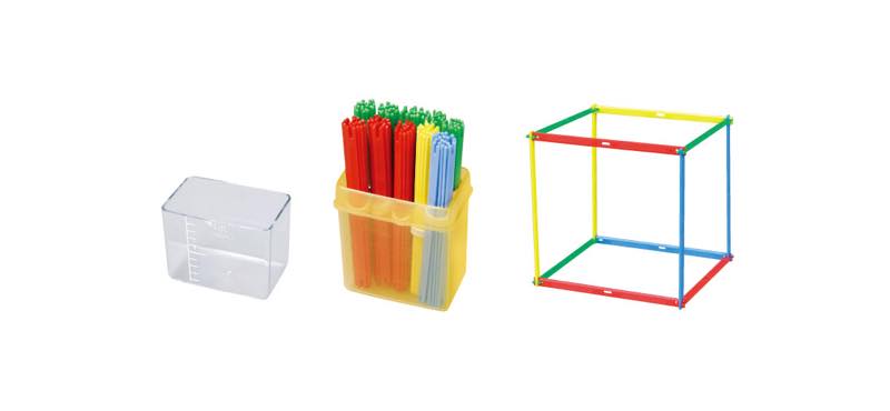
Counting sticks, or “kazoe-bou,” are colorful plastic sticks used in Japanese math teaching materials to teach the concept of numbers. They are particularly effective for learning the decimal system, as bundles of 10 sticks are used to represent the tens position.
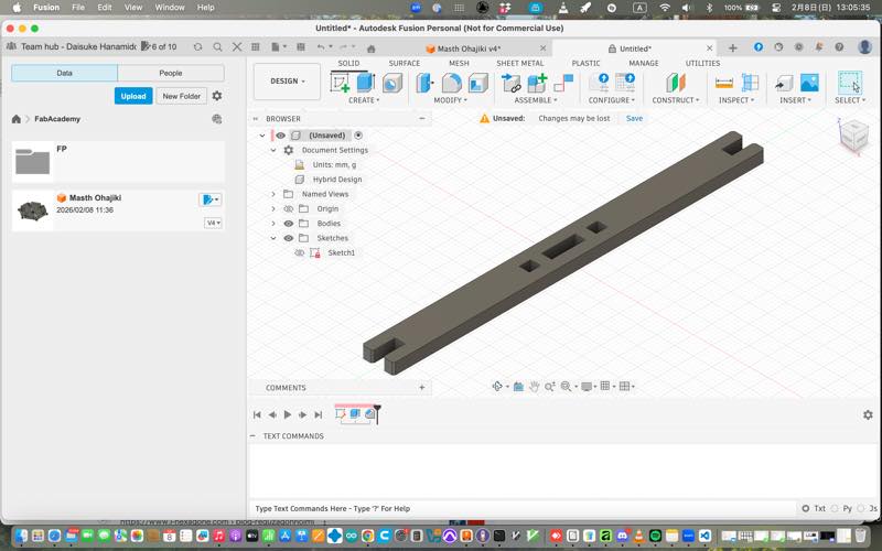
I modeled the counting sticks in the same way and exported them as SVG.
counting-sticks.f3d 3
counting sticks.svg 4
Laser Cutter
What is a Laser Cutter?
A laser cutter is a computer-controlled machine that uses a high-power laser beam to cut or engrave materials with extreme precision. It works by directing the output of a high-power laser through optics to melt, burn, or vaporize the material.
Types of Lasers
CO2
CO2 lasers use a gas mixture to produce a laser beam and are the most common type for cutting non-metallic materials like wood, acrylic, and leather. They are versatile and cost-effective for various hobbyist and industrial applications.
Diode
Diode lasers are compact, affordable, and energy-efficient, often found in entry-level engraving machines. While they are less powerful than CO2 or Fiber lasers, they are excellent for detailed engraving on wood and soft materials.
Fiber
Fiber lasers are solid-state lasers designed specifically for high-speed cutting and marking of metals and hard plastics. They offer a long lifespan, low maintenance, and exceptional precision due to their extremely small beam diameter.
UV
UV lasers use a short wavelength to perform “cold processing,” which allows for marking and cutting without damaging the surrounding material with heat. They are ideal for delicate tasks on glass, ceramics, and sensitive electronic components.
YAG
YAG lasers are versatile solid-state lasers often used for heavy-duty metal marking and thin-sheet cutting. Though increasingly replaced by fiber lasers, they remain valued for specific industrial processes requiring high peak power.
Drive Method
XYasix
The XY-axis drive method, or gantry system, moves the laser head along a physical rail system to cover the entire work area. This method is ideal for large-scale cutting because it maintains consistent precision across a flat surface.
garubano
The Galvano method uses high-speed motorized mirrors to direct the laser beam, allowing for incredibly fast movement over a smaller area. It is primarily used for high-speed marking and engraving where production time is critical.
Use Laser Cutter
it is missing size return fujion cange 150mm to 15mm
thrue size
cuting
finish
meke things
Vinyl Cutter
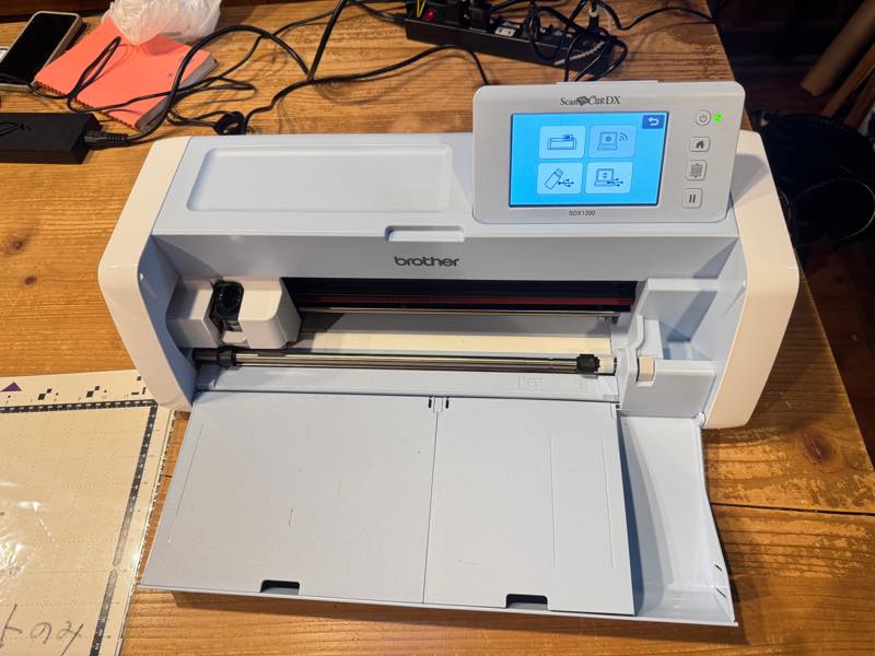
I edited the Fablab Kamakura logo in Inkscape and printed it out.
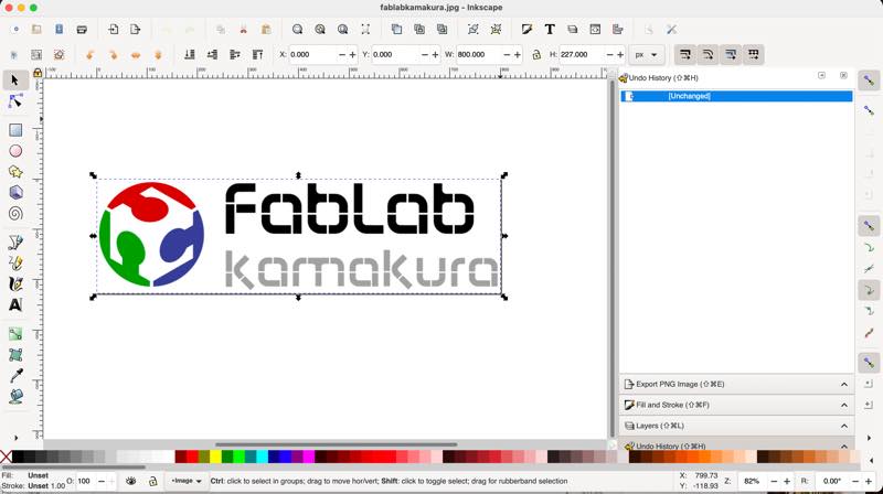
I traced the edges (black and white border) of the image in Inkscape to create the cut data.
I loaded the resulting outline data into a vinyl cutter.
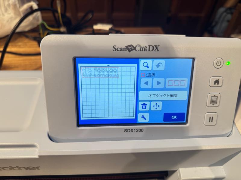
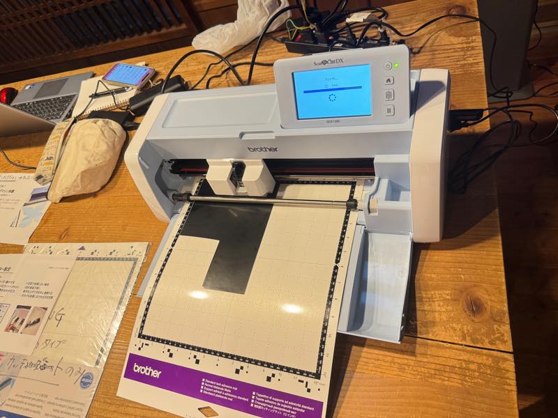
I set the cutting sheet.
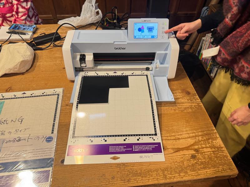
I cut it.
I peeled off the unnecessary parts.

I attached a transparent release sheet and trimmed the shape with scissors along with the backing paper to complete the process.
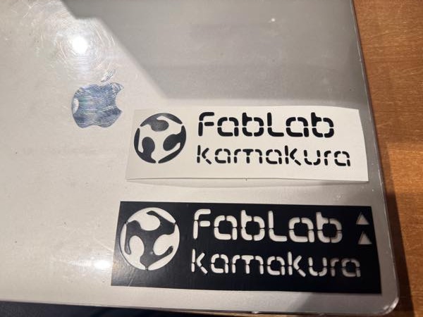
fablabkamakura.svg 5