7. Computer controlled machining
Assignments and Assessment this week
Group assignment:
- Complete your lab’s safety training
- Test runout, alignment, fixturing, speeds, feeds, materials and toolpaths for your machine
- Document your work to the group work page and reflect on your individual page what you learned
Individual project
- Make (design+mill+assemble) something big (~meter-scale) • extra credit: don’t use fasteners or glue • extra credit: include curved surfaces • extra credit: use three-axis toolpaths
Learning outcomes
- Demonstrate 2D design development for CNC milling production
- Describe workflows and operation for large format CNC machining
Have you answered these questions?
- Linked to the group assignment page
- Reflected on your individual page what you learned of your labs safety training
- Documented how you designed your object and made your CAM-toolpath
- Documented how you milled and assembled your final product (including setting up the machine, fixturing, feeds, speeds etc.)
- Described problems and how you fixed them
- Included your design files and ‘hero shot’ of your final product
Group Assignment
Here is a group assignment page
Research
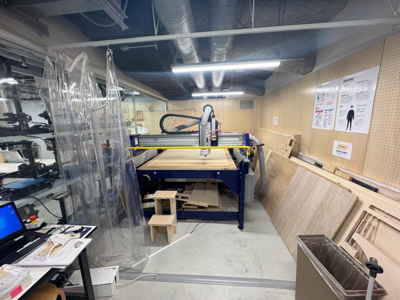
Tom and Tony, it was a great class! Thank you. This week, there was no large CNC installed at FabLab Kamakura, so we used the ShopBot installed at FabLab Minato Mirai. At Minato Mirai, we also met Murasaki, a 2017 graduate. Also, this time, Asako, a 2015 graduate, came as a special lecturer. We’d like to express our sincere gratitude to everyone who provided us with such a wonderful environment. Thank you very much.
How do you make
Construction of a TV studio by r-crew *Japanise
SANKEN Engineering Stage Set Scenery
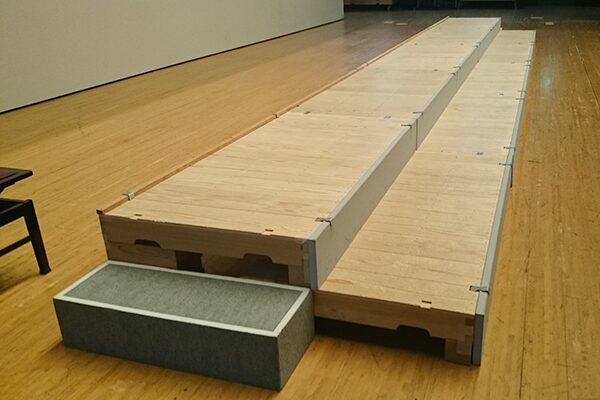
What I made this week was a “hakouma,” a device commonly used in Japanese stage productions. It serves as a base when assembled with a platform stage, and is often used in place of a chair or step stool. It’s based on the shaku (approx. 45cm) measurement, which is similar to the American inch. It measures 1.5 shaku (approx. 30cm) x 1 shaku (approx. 30cm) x 5 sun (approx. 15cm), with a 1:2:3 ratio, allowing the platform height to be adjusted depending on how it’s placed.
A similar American example is the Matthews Apple Box, used in Hollywood.

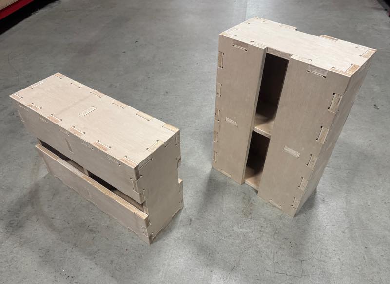
However, hakouma can be quite inconvenient when transporting them to a set. Because they’re fastened together with nails and can’t be disassembled, they’re bulky. Transporting a large number of hakouma is like transporting boxes filled with air. To address this issue, I designed a interlocking hakouma.
Design of an Interlocking Hakouma
I used Fusion360 to design three interlocking parts. The plate inserted in the middle is structurally necessary, otherwise the plate would break when a heavy object was placed on it. Also, since the inner 90-degree corners cannot be machined, I drew a 6.35mm (1/4 inch) circle, the same diameter as the end mill, and created a T-bone or dog bone to allow the end mill to escape, allowing for a right-angle fit.
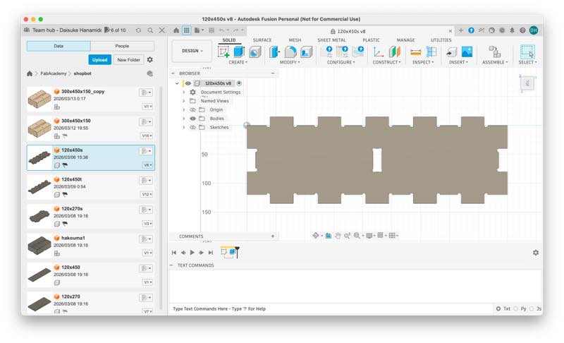
I also applied parametric design techniques to the design, allowing the joint size to be adjusted based on the fit test results for the group assignment.
Click here for the Fusion last data.1
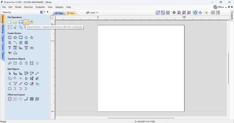
Creating Cutting Paths and Post-Processing in Vcarve
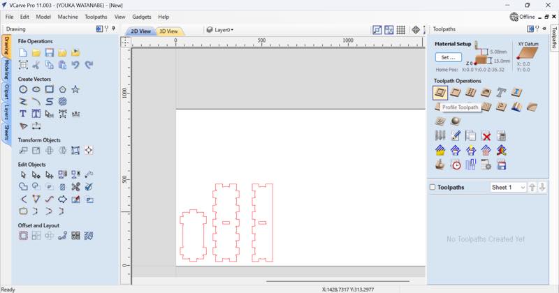
The data designed in Fusion was imported into Vcarve, a software installed on FabLab Kamakura’s PC, to create the cutting paths.
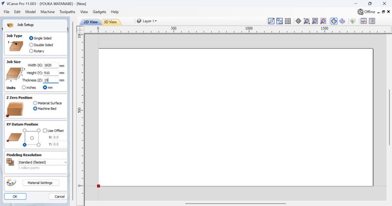
Machining Size
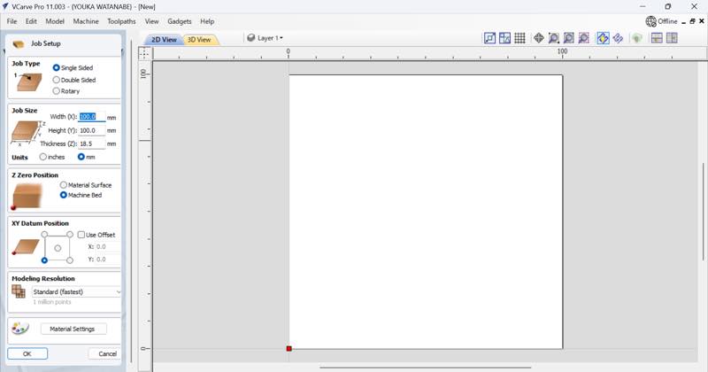
Job Type: Single-Sided Job Size: Width: 1820, Height: 910, Thickness: 15 (units in mm) The lauan lumber core material used here is a 15mm thick, 910mm x 1820mm (3 shaku x 6 shaku) board, commonly referred to as a “saburoku” board. Z Zero Position: Machine Bed The material surface sets the z zero point on the board to be machined, so depending on the warping of the material, there may be areas that cannot be cut. Once this is set, press OK to finish the design.
| Parameter | Value |
|---|---|
| Job Type | Single Sided |
| Job Size Width (X) | 1820 mm |
| Job Size Height (Y) | 910 mm |
| Job Size Thickness (Z) | 15 mm |
| Z Zero Position | Machine Bed |
| XY Datum Position | Bottom-Left |
| Modeling Resolution | Standard (fastest) |
Import File
DXF files are recommended, but there’s a fee to export them in Fusion.
I wanted to be able to modify the file and import it into Vcarve in the future without paying a fee (even though I had activated Academy via Luchiana’s email), so I tried other output methods.
First, I output an .svg using Shaper Utilities, which I used in the laser cutter week in week 3, but the scale was wrong, with 300mm becoming 3mm, resulting in inconsistent dimensions. Next, I looked at files that can be imported into Vcarve and exported from Fusion, and found that a CAD file called SketchUp (.skp) was compatible.
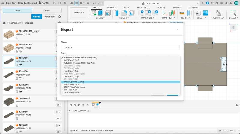
I tried that, and it worked fine.
However, because the paths were integrated, I had to later undo the integration between the outline and hole paths.
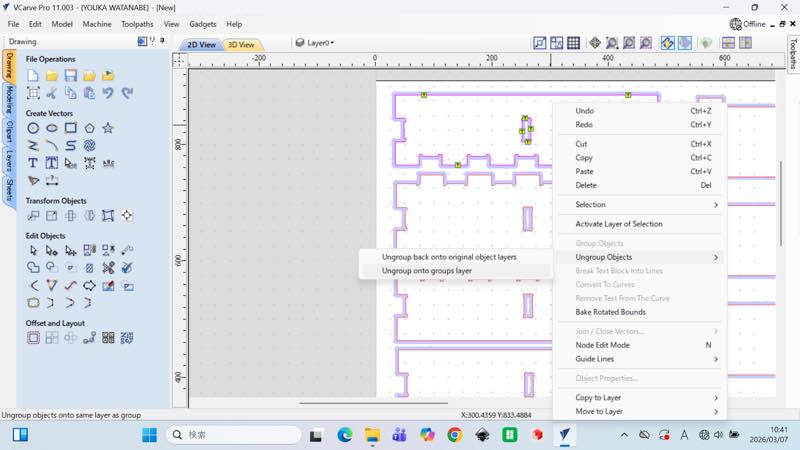
The .skp last file is here.2
Creating a Cutting Path
Next, create a cutting path.
| Parameter | Value |
|---|---|
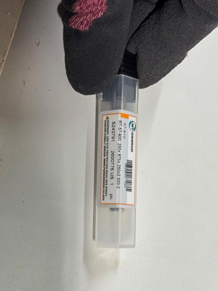
| Tool Information | |
| Tool Name | 57-910Downcut1/4 |
| Tool Type | End Mill |
| Geometry | |
| Units | inches |
| Diameter (D) | 0.25 inches (6.35mm) |
| No. Flutes | 2 |
| Cutting Parameters | |
| Pass Depth | 0.125 inches (3.1750mm) |
| Stepover | 0.1 inches(2.54mm) (40 %) |
| Feeds and Speeds | |
| Spindle Speed | 18000 r.p.m |
| Feed Units | mm/sec |
| Feed Rate | 75 mm/sec |
| Plunge Rate | 30 mm/sec |
| Chip Load | 0.125 mm |
| Tool Number | |
| Tool Number | 1 |
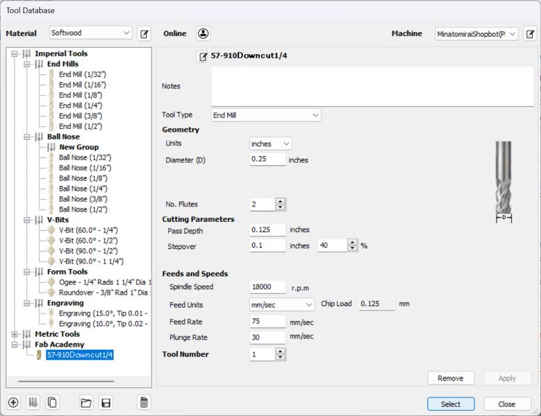
To create a cutting path, set the cutting speed (feed) based on the tool diameter, machine spindle rotation speed, and material properties.
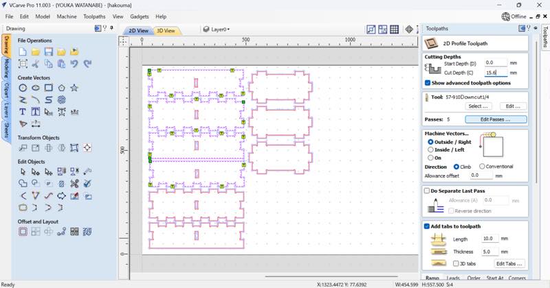
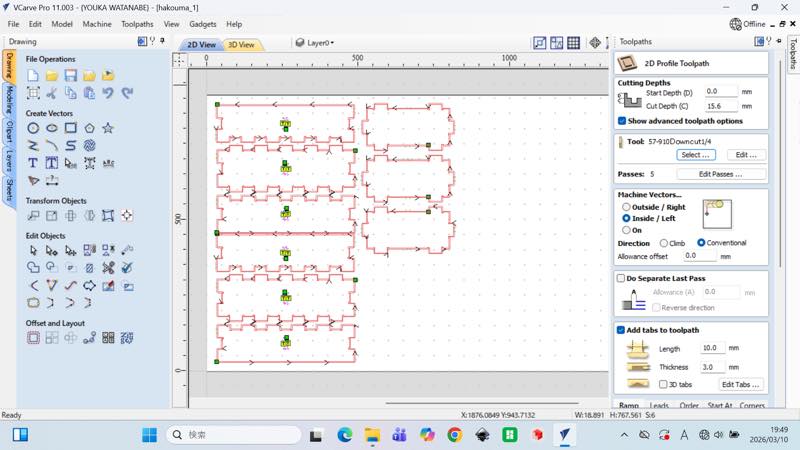
For example, the cut depth was initially 15.1mm, but it was changed to 15.6mm because the material couldn’t be cut through during the test cut. Also, the path settings differ for combination pocket machining and outer shape machining. This is the pocket setting.
| Cutting Depths | Outside Value | Inside Value |
|---|---|---|
| Start Depth (D) | 0.0 mm | 0.0 mm |
| Cut Depth (C) | 15.6 mm | 15.6 mm |
| Show advanced toolpath options | ✓ | ✓ |
| Tool | Outside Value | Inside Value |
|---|---|---|
| Tool Name | 57-910Downcut1/4 | 57-910Downcut1/4 |
| Passes | 5 | 5 |
| Machine Vectors | Outside Value | Inside Value |
|---|---|---|
| Vector Position | Outside / Right | Inside / Left |
| Direction | Climb | Conventional |
| Allowance offset | 0.0 mm | 0.0 mm |
| Add tabs to toolpath | Outside Value | Inside Value |
|---|---|---|
| Enable Tabs | [✓] | [✓] |
| Length | 10.0 mm | 10.0 mm |
| Thickness | 5.0 mm | 3.0 mm |
| 3D tabs | - | - |
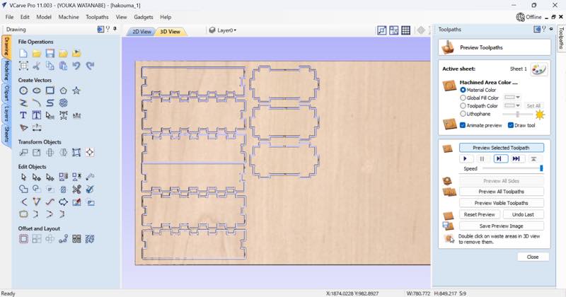
3D tool paths
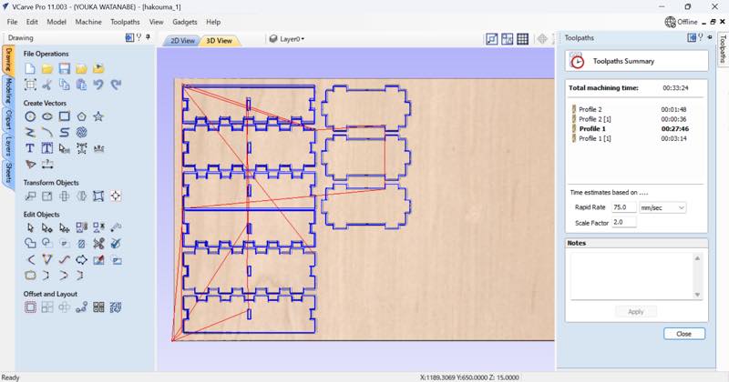
How long will it take?
Post-Processing

Once the cutting path is complete, generate a .sbp G-code file to be read by the ShopBot. This is a G-code file in a format suitable for the ShopBot, and once this format is generated, the ShopBot can perform machining.
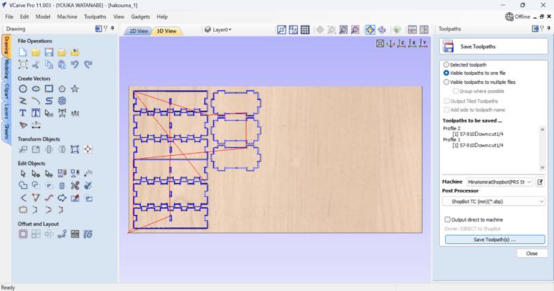
The Vcarve last file is here.3
The .sbp last file is here.4
Machining with a ShopBot
The general steps for machining are: Power on the ShopBot Launch the ShopBot Control Software Check that each axis moves.
Processing can be done by loading the .sbp file into the ShopBot Control Software, but before that, we prepared the ShopBot so that processing could begin.
| Fraction (inch) | Decimal (inch) | Metric (mm) |
|---|---|---|
| 1/8 | 0.1250 | 3.1750 |
| 3/16 | 0.1875 | 4.7625 |
| 1/4 | 0.2500 | 6.3500 |
| 5/16 | 0.3125 | 7.9375 |
| 3/8 | 0.3750 | 9.5250 |
| 7/16 | 0.4375 | 11.1125 |
| 1/2 | 0.5000 | 12.7000 |
| 9/16 | 0.5625 | 14.2875 |
| 5/8 | 0.6250 | 15.8750 |
| 11/16 | 0.6875 | 17.4625 |
| 3/4 | 0.7500 | 19.0500 |
| 13/16 | 0.8125 | 20.6375 |
| 7/8 | 0.8750 | 22.2250 |
| 15/16 | 0.9375 | 23.8125 |
| 1 | 1.0000 | 25.4000 |
Crash Point
Chuck’s electrical conductivity
When attempting to locate the Z0 origin, the mill crashed into an aluminum plate, likely due to a loss of electrical conductivity. The chuck’s electrical conductivity was poor, so I established a circuit using a less rusty bolt or similar.
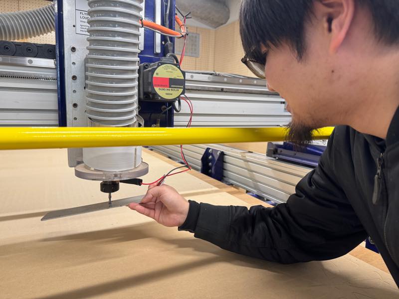
Not goot toch senser
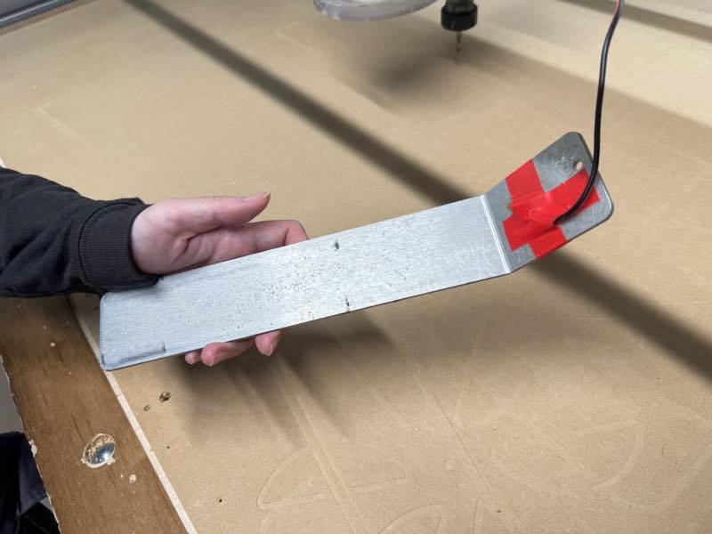
meny Crash endmills
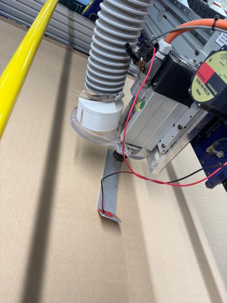
Good Z0 origin
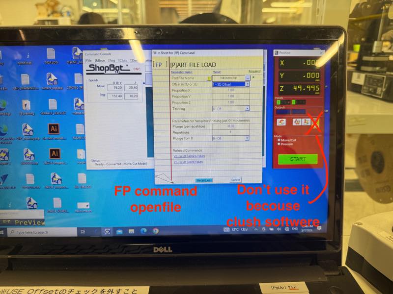
Not moved axis open the .sbp file
When I returned to the origin and attempted an air pass, the control software crashed because I operated the machine with a file open using the FP command. After that, I tried to restart the software, but it would display an error and would not start up, so Asako reinstalled the control software for me. At this time, I didn’t have a backup of the ini file, so I lost track of the offset from the machine origin. Fortunately, I hadn’t moved the X and Y axes from the origin, so I was able to recover. The only other change I made was changing inches to mm.
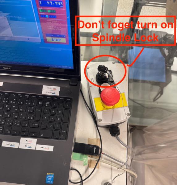
Check the spindle lock
I nearly crashed after pressing start with the spindle locked, so I did an emergency stop.
Safe distance
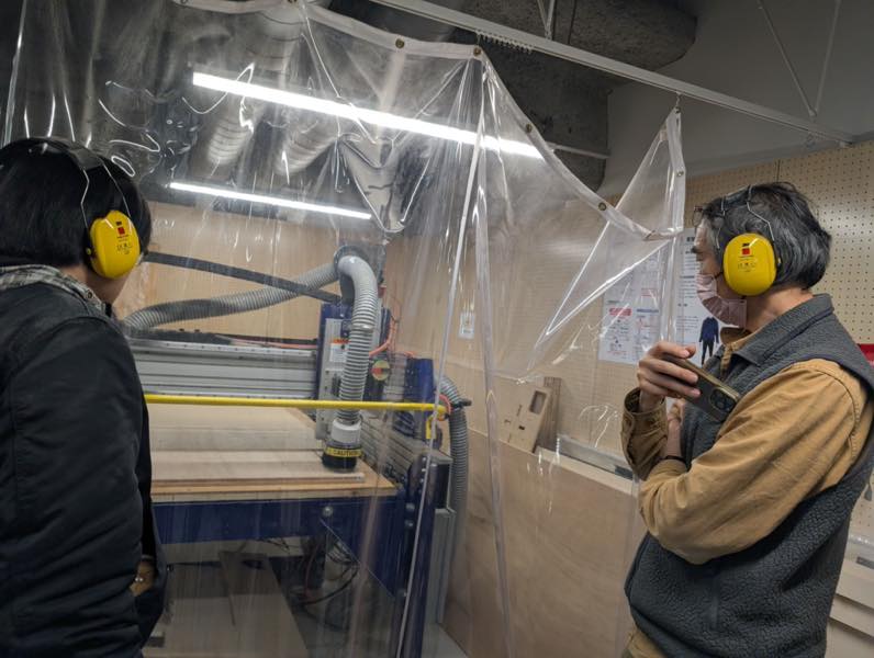
During processing, the curtains were closed, safety equipment was worn, and the workers monitored the process from a safe distance to prevent injury from flying debris, while also being able to immediately stop the machine if anything happened.
Three passes
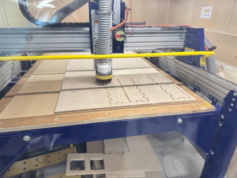
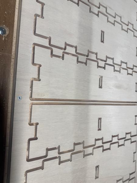
The first time, the depth was too shallow to cut through. I added depth from -0.3mm to -0.6mm and cut in one pass, finishing with only a thin layer remaining.
I heard that the hole path would be narrower than it actually was and wouldn’t fit, so I made the hole diameter 0.1mm larger than the actual size, but it ended up being too loose.
Fortunately, it fit within half the board, so I cut it again.
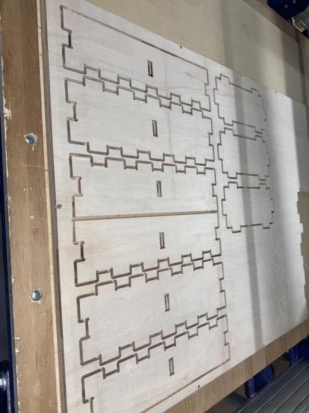
This time it cut fine.
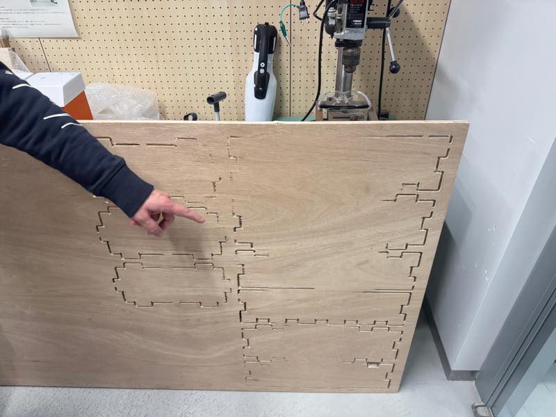
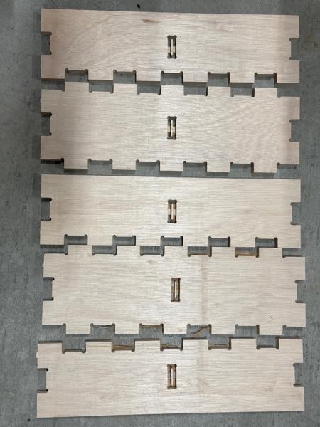 After that, I brought it back from the lab and sanded it down and removed the tabs.
I used an electric sander, chisel, and hammer.
After that, I brought it back from the lab and sanded it down and removed the tabs.
I used an electric sander, chisel, and hammer.
As expected, the first hole was too loose, but the second hole fit perfectly.
Finished
After that, I found a Fusion to ShopBot post processor ShopBot post prosseser to Fusion Fusionhakouma.sbp File 5
This plugin automatically generates Dogbone, which was introduced in Asia Review. I wish I had known about it sooner.That way I wouldn’t have had to draw so many borders.
Dogbone addin for fusion 360 download a self extracting file or extracting file install at the user file reboot fusion
Nifty Dogbone for Autodesk® Fusion® - 60-day full functionality trial - can purchase a perpetual license for $20 USD