11. Networking and Communications
Contents
Assignments and Assessment this week
Connecting with other products
Assignments and Assessment this week
Group assignment
- Send a message between two projects
- Document your work to the group work page and reflect on your individual page what you learned
Individual assignment
- design, build and connect wired or wireless node(s) with network or bus addresses and a local input and/or output device(s)
Learning outcomes
- Demonstrate workflows used in network design
- Implement and interpret networking protocols and/or communication protocols
Have you answered these questions?
- Linked to the group assignment page
- Documented your project and what you have learned from implementing networking and/or communication protocols.
- Explained the programming process(es) you used.
- Ensured and documented that your addressing for boards works
- Outlined problems and how you fixed them.
- Included design files (or linked to where they are located if you are using a board you have designed and fabricated earlier) and original source code.
- Included a ‘hero shot’ of your network and/or communications setup
Group Assignment
Here is a group assignment page
This week, after communicating with Koushi-san using UART serial communication, I worked on a separate assignment involving DMX communication.
I work as a technical specialist at a stage lighting company in Japan.
My final project is to build a DMX measuring device.
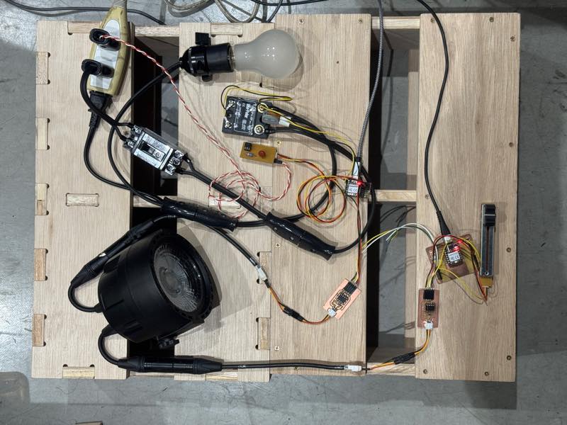
This week’s is to focus on DMX, which is closely related to this project. Therefore, I made a minimam DMX system. That is incluthe time to send one data signal Start/Stop bit MX signal output and a DMX signal input to light bulbs dimming.
What is DMX?
DMX is a digital communication standard derived from RS485 and still widely used in the stage lighting field. Because it transmits 0 and 1 signals differentially, it is highly resistant to noise. Theoretically, up to 32 devices can be connected on a single communication bus line, and signal lines can be extended up to 300m in length.
In terms of hardware, if you can connect the TX and RX terminals of the UART to the MAX485 chip for RS485 output and enable serial communication at 250kbps, you can create a working system.
Communication protocol
| Baud rate | 250kbps |
| Start bit | 1 bit (LOW) |
| Stop bit | 2 bits (HIGH) |
| Data bits | 8 bits (1 byte) |
This is the configuration. Baud rate refers to the number of HIGH (1) and LOW (0) signals sent per second. A baud rate of 250 kbit/sec means 250,000 1s and 0s can be sent.
Furthermore, the time to send one data signal Start/Stop bit is 1/250,000 seconds, meaning it takes 4 μs to send one data signal. Incidentally, one HIGH (1) or LOW (0) data signal is called a 1-bit.
data bit
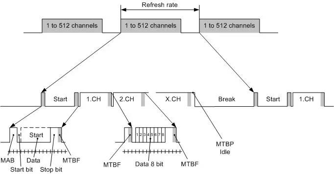
The essence of DMX is the 8 bits (1 byte) of data, each consisting of eight 1-bit signals, with values ranging from 0 to 255. This is also called a data bit.
start/stop bit
These data bits are arranged from 1 to 512, but simply arranging them makes it difficult to distinguish the data boundaries, leading to data loss. Therefore, a 1-bit LOW signal is added as a start bit at the beginning of the data bits, and a 2-bit HIGH signal is added at the end. This 11-bit sequence of start, data, and stop bits constitutes the data for one DMX channel.
DMX Address
The DMX address is a number that determines which data point to use first in the sequence of incoming data.
by TamaTechlab
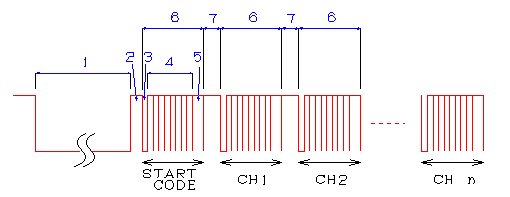
Start Code
Incidentally, when viewing the waveform on an oscilloscope, there is another data point, number 0, before signals 1 through 512. This is called the start code, and in the case of dimming control signals, 0 is always sent. If anything else is sent, it is recognized as something other than a DMX dimming control signal, and dimming control will not be possible.
Break, Mark After Break
by TamaTechlab
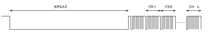
DMX repeatedly sends 513 data points, including these, and up to this point, the data is almost the same as RS485. However, when sending data repeatedly, since the same width of 11 bits (44 μs) is being sent, it becomes difficult to determine the beginning. This is where the most distinctive features of DMX, Break and Mark After Break, come in.
The Break signal is a long, low-level signal used to find the beginning of the data, defined as being between 88 μs (22 bits) and 1 second, with a range in length.
The Mark After Break signal is a high-level signal between 8 μs (2 bits) and 1 second, existing to distinguish between the Break and the start bit, as both signals are low.
However, because these two signals have a range in duration from the minimum value up to 1 second, compatibility issues often occur. Nevertheless, the allowed delay time between sending one signal to one channel and sending the next is 1 second, so a signal will be sent at least once every 1 second.
Reference site
Theater Technisch Lab BV : What is the DMX512 protocol ?
DMX512 PrimerWritten by Doug FleenorDoug Fleenor
production-partner.wiki dmx-512
Japanese
Xiao RP2040 DMX
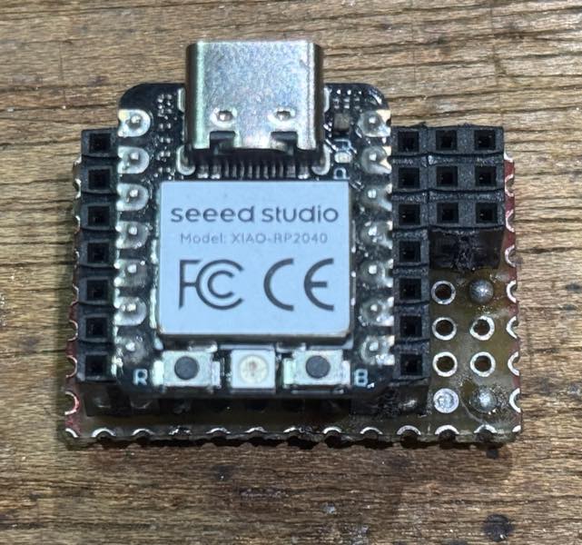
While there weren’t many examples of DMX projects using Xiao, I found several examples using Arduino and Raspberry Pi Pi-Pico. Therefore, this time, I aimed to create a project that could transmit and receive DMX signals using the RP2040.
DMX512 control with Seed XIAO RP2040 and MAX485
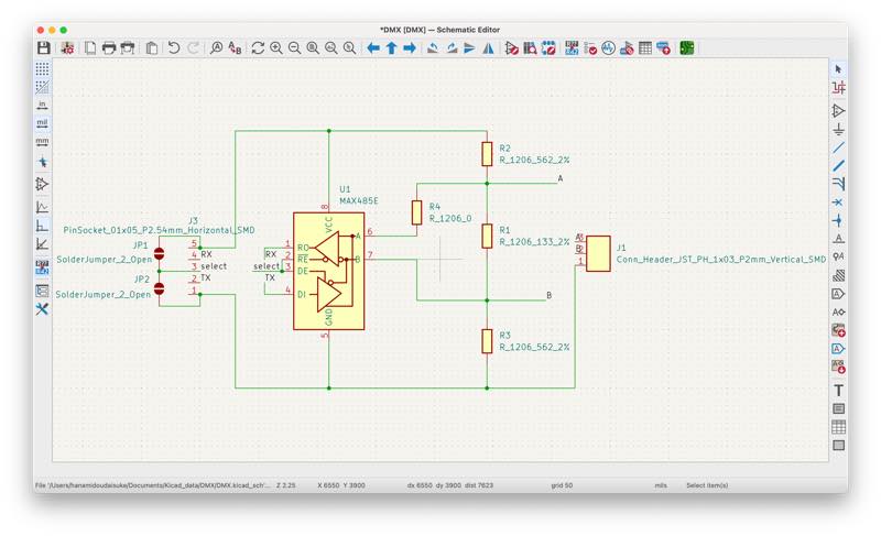
I had the MAX485 driver mentioned on this site, so I used it to create the signal input/output circuit.
Circuit Diagram
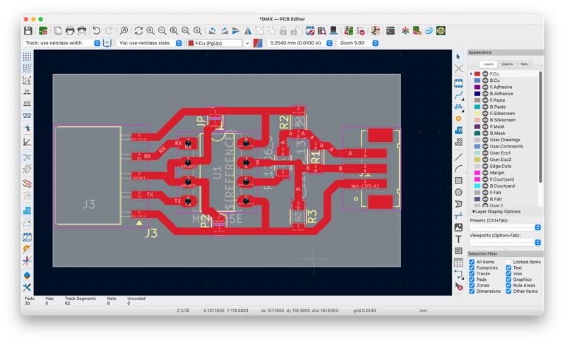
Wiring Diagram
KICAD Data1
Gerber File2
rml File3
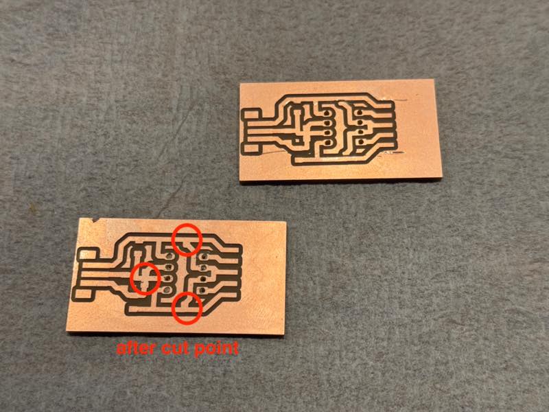
missing milld pcb
Jumper pads were placed to allow communication with fewer wires. It can also be operated by desoldering and specifying the port. Pads for pull-up/down resistors for port stabilization and a 120-ohm signal termination resistor were placed on the DMX signal output circuit. It will work even without them. There was one spot where I absolutely had to use a 0-ohm jumper.
I tried using the following library for the DMX output:
The sample code uses software serial, and both INPUT and OUTPUT worked when connected to Xiao GPIO0.
At this point, it was 6 PM on Sunday, FabLab Kamakura was closing, and our work time was over, leaving the rest to be done at home.
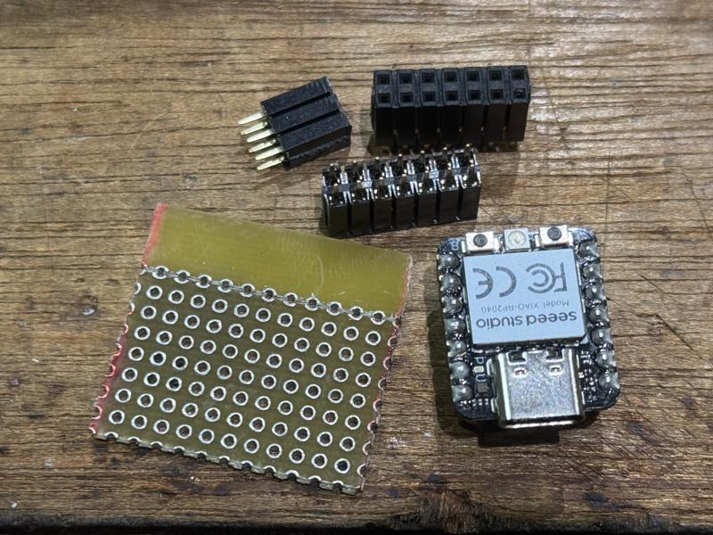
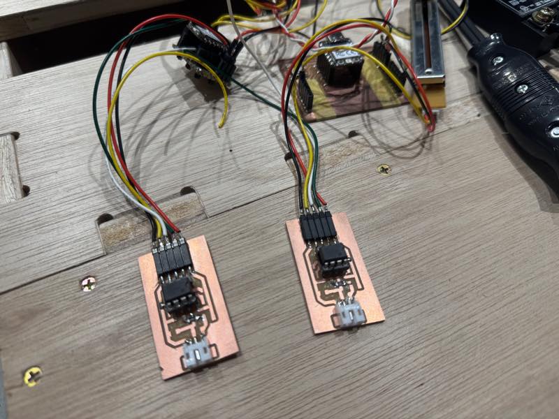
I realized that communication wouldn’t work without two boards, but I didn’t have time to mill them, so I went home, soldered a scrap of Universal PCB and a two-row pin socket to make a makeshift board, and implemented the output side.
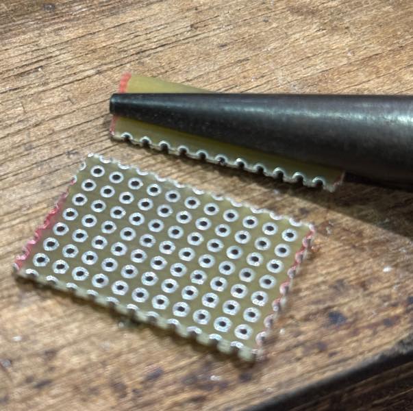
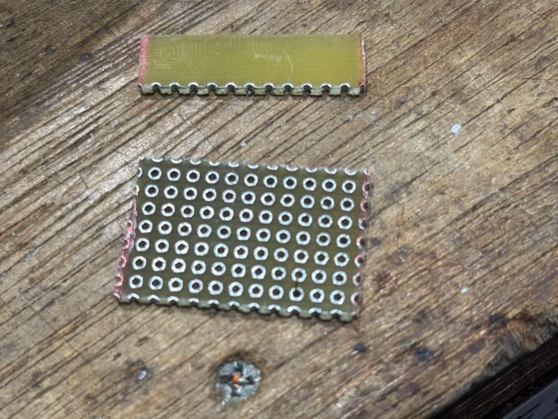
cut pcb
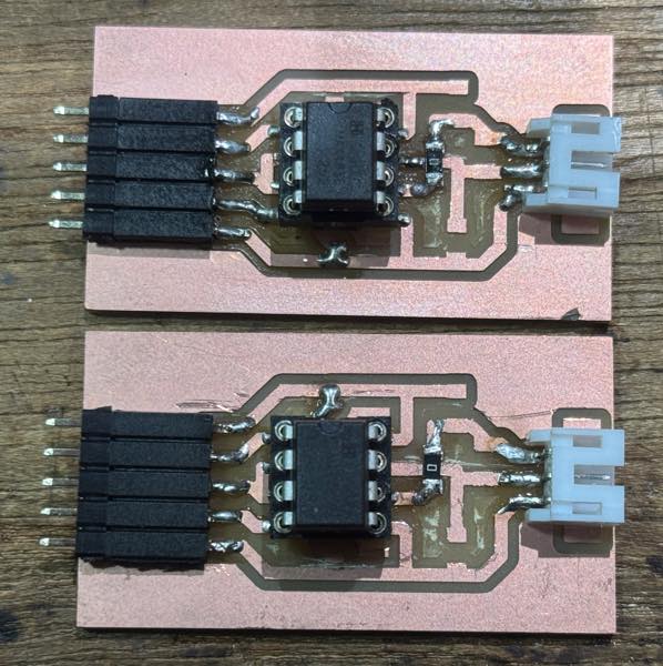
soldering
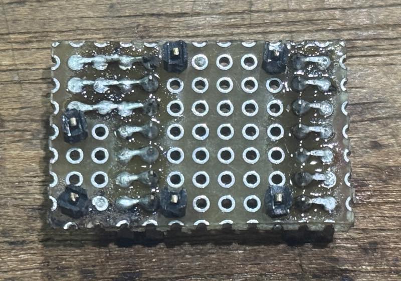
finish
I didn’t have enough time this week, but I want to finish milling pcb the next week.
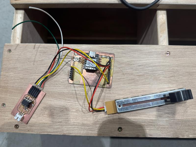
Input/Output wiring to the main boards
DMX output device
I implemented a program that changes the value of a DMX using the slider used in the input section, and outputs the result. The current slider value was output as an 8-bit value at all addresses from 1 to 512.
The program is here.
#include <Arduino.h>
#include <DmxOutput.h>

// Declare an instance of the DMX Output
DmxOutput dmx;

// Create a universe that we want to send.
// The universe must be maximum 512 bytes + 1 byte of start code
#define UNIVERSE_LENGTH 512
uint8_t universe[UNIVERSE_LENGTH + 1];

void setup()
{
    // Start the DMX Output on GPIO-pin 0
    dmx.begin(0);

    analogReadResolution(8);

    // Set all channels in the universe to the max allowed value (512)
    for (int i = 1; i < UNIVERSE_LENGTH + 1; i++)
    {
        universe[i] = 0;
    }
}

void loop()
{
    int val = analogRead(A0);
    //10bit=1/4 analogRead(A0) >> 2
    //12bit=1/16 analogRead(A0) >> 4

    for (int i = 1; i < UNIVERSE_LENGTH + 1; i++)
    {
        universe[i] = val;
    }
    // Send out universe on GPIO-pin 1
    dmx.write(universe, UNIVERSE_LENGTH);

    while (dmx.busy())
    {
        /* Do nothing while the DMX frame transmits */
    }
    // delay a millisecond for stability (Not strictly necessary)
    delay(1);
}
Connection photo
DMX dimming device
go to the Non-Zero-Crossing SSR Output week10
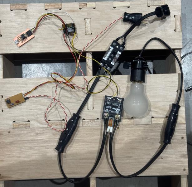
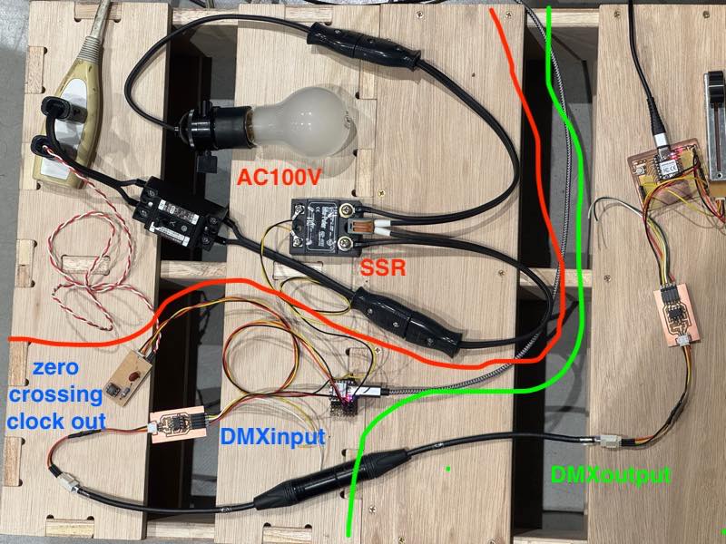
The 100V dimming system is complete. The DMX uses a single address, allowing brightness adjustment between 0 and 255. In this case, address 1 was set in the program. The libraries used were Pico-DMX and dimmable-light, with the necessary parts implemented from the sample code.
The output circuit consists of a DMX receiver, a main RP2040 board, an AC waveform zero-crossing detection circuit, and an SSR circuit. See the output section for details.
The output program is here.
#include <Arduino.h>
#include <dimmable_light.h>
#include "DmxInput.h"
DmxInput dmxInput;

#define START_CHANNEL 1
#define NUM_CHANNELS 1
#define USER_LED_RED 17
#define USER_LED_GREEN 16

const int syncPin = 26; //zero_cross
const int thyristorPin = 27; //SSR
DimmableLight light(thyristorPin);

volatile uint8_t buffer[DMXINPUT_BUFFER_SIZE(START_CHANNEL, NUM_CHANNELS)];

void setup()
{
    // Setup our DMX Input to read on GPIO 0, from channel 1
    dmxInput.begin(0, START_CHANNEL, NUM_CHANNELS);
    dmxInput.read_async(buffer);

    // Setup the onboard LED so that we can blink when we receives packets
    pinMode(LED_BUILTIN, OUTPUT);
    pinMode(USER_LED_GREEN, OUTPUT);
    digitalWrite(LED_BUILTIN, HIGH);
    digitalWrite(USER_LED_GREEN, HIGH);

    analogWriteFreq(50);
    analogWriteRange(255);
    pinMode(USER_LED_RED, OUTPUT);
    analogWrite(USER_LED_RED, 255);

    //dimming setup
    //DimmableLight::setFrequency(50); //AC Frequency 50/60 Hz
    DimmableLight::setSyncPin(syncPin);
    // VERY IMPORTANT: Call this method to activate the library
    DimmableLight::begin();
}

void loop()
{
    delay(30);
    //DMX no data
    if(millis() > 100+dmxInput.latest_packet_timestamp()) {
        digitalWrite(LED_BUILTIN, HIGH);
        Serial.println("no data!");
        return;
    }
    ///* Print the DMX channels
    Serial.print("Received packet: ");
    for (uint i = 0; i < sizeof(buffer); i++)
    {
        Serial.print(buffer[i]);
        Serial.print(", ");
    }
    Serial.println("");

    analogWrite(USER_LED_RED,255-buffer[1]);
    light.setBrightness(buffer[1]);

    //analogWrite(SSR,buffer[1]);

    /*//SSR sw
    if(128<buffer[1]){
        digitalWrite(SSR,HIGH);
    }else{
        digitalWrite(SSR,LOW);
    }
    */


    // Blink the LED to indicate that a packet was received

    digitalWrite(LED_BUILTIN, LOW);
    delay(10);
    digitalWrite(LED_BUILTIN, HIGH);


}
The AC waveform during 100V dimming is here.
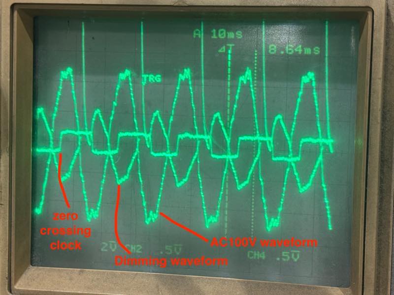
It appears to be tracking the zero-crossing clock point, but the waveform isn’t what I expected. There’s a problem with the program. First, it needs to react not only to the falling edge of the clock but also to the rising edge, otherwise the dimming will only apply to half of the AC power. Also, the SSR’s operating point needs to be delayed to match the zero-crossing point of the AC waveform, rather than when the clock arrives. However, it is still working to some extent in this state.
Operation confirmed with DMX connection.
It worked!!
Connecting with other products
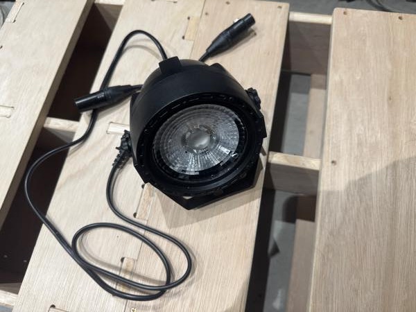 Mini COB LED Par byAliexpress
I incorporated this product into a custom-made DMX circuit and confirmed that it actually operates in RGB 3-channel mode by specifying the start address. Regarding DMX addresses The start address is set to 2, which is in a mode to adjust the brightness of the three RGB LEDs, so addresses up to 4 are received and used for this product to operate.
DMX does not use 3-pin XLR connectors! This is clearly stated in the standard, but many cheap Chinese devices use 3-pin XLR connectors.
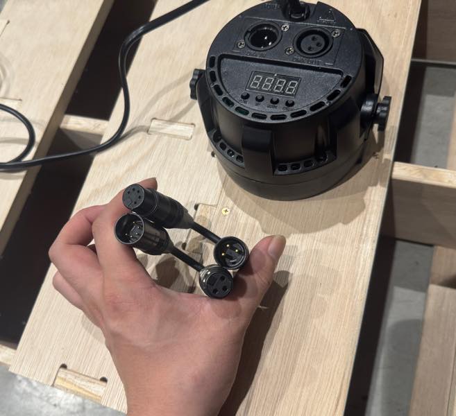
Please convert the 3-pin XLR connector to a 5-pin XLR connector.
I connected everything and confirmed that it worked.
It worked!!
This time, due to time constraints, I changed all the address values simultaneously, but by implementing a switch to change addresses, it is possible to change individual addresses.
Meaning of DMX Addresses
DMX always sends signals from the output device. For example, if the DMX output sends 255 to DMX address 1, 255 to 2, 0 to 3, 255 to 4, and so on, if the dimming device’s address is programmed to 1 on the DMX receiving side, the dimming device will constantly receive changes in DMX address 1.
Also, if the LED Par’s address is set to 2 and the mode is set to a mode where RGB changes with the movement of the three channels, then address 2 will be 255, red will be fully lit; address 3 will be 0, green will be off; and address 4 will be 255, blue will be fully lit. Therefore, the LED Par will light up in magenta.
Useful links
Design Files
the time to send one data signal Start/stop bit
the time to send one data signal Start/Stop bit