10. Output Devices

Motorized fader
Non-Zero-Crossing SSR
Assignments and Assessment this week
Group assignment
Measure the power consumption of an output device. Document your work on the group work page and reflect on your individual page what you learned.
Individual assignment
Add an output device to a microcontroller board you’ve designed and program it to do something.
Learning outcomes
Demonstrate workflows used in controlling an output device(s) with MCU board you have designed.
Have you answered these questions?
Linked to the group assignment page. Documented how you determined power consumption of an output device with your group. Documented what you learned from interfacing output device(s) to microcontroller and controlling the device(s). Linked to the board you made in a previous assignment or documented your design and fabrication process if you made a new board. Explained how your code works. Explained any problems you encountered and how you fixed them. Included original source code and any new design files. Included a ‘hero shot’ of your board.
Group Assignment
Here is a group assignment page
This week, in a group project, we learned about Ohm’s law, parallel circuits, series circuits, how to calculate the power consumed in those circuits, how to handle DC regulated power supplies, and how to use the current measurement function of a multimeter.
Motorized fader
To operate the motorized fader mentioned in the input week, we created a motor driver board and performed a test plug-and-play to verify its operation. The reason the input week was shorter was because we were preparing for this week’s work.

First, we checked what voltage the motor operates at by connecting it directly to a regulated power supply. We thought it would work from 5V, but in reality, it wouldn’t operate stably unless we applied around 6V, as it would get stuck midway through the voltage cycle.(Later, I discovered that the datasheet contained the motor specifications. According to this, the rated voltage is 10V DC, the operating voltage range is 6-11V DC, the starting current is 800mA, the movement speed at the rated voltage is 20mm/0.1sec, and the current flowing when the lever is fixed and the motor is locked is 400-800mA.)
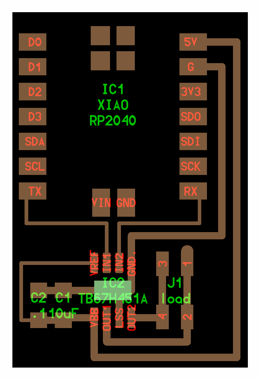
Therefore, a separate power supply design is necessary, and this time, it was decided to supply power from a stabilized power supply. Also, since the direction of rotation needs to be reversed to move it up and down, an H-bridge circuit is required for operation from the microcontroller. This time, I used the motor driver TB67H450FNG provided by instructor Kae Nagano (2019).

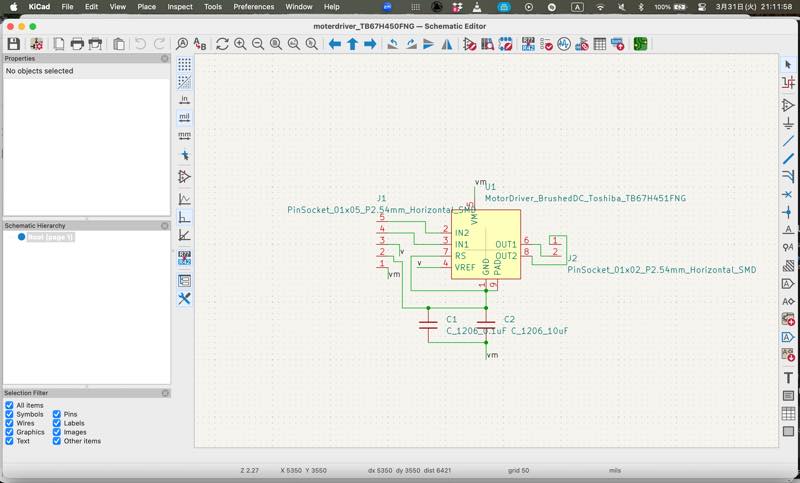
The circuit was based on Neil’s TB67H451AFNG example, and I added a noise-suppressing capacitor to the power supply circuit. Also, in the example, the chip power supply and motor power supply were shared, but I decided to separate the motor power supply to accommodate 6V.
KiCad data 1
Designed circuit diagram
Wiring diagram
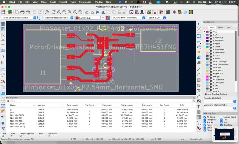
Gerber data output with Fabrication tool kit plugin 2
PNG file output with gerber2png plugin 3
Note that the drill holes will be larger by the diameter of the mill used, reducing the land area. If this is not a concern, you can proceed with milling directly into Mods.
RML file output from Mods 4
Completed milling of the circuit board.
After soldering.
Initially, I connected it to a microcontroller and performed a test run using a sample program, but it didn’t work, so I investigated the cause.
I decided to perform a test run using 5V without connecting to a microcontroller.
I connected the H-bridge inputs directly to 5V and ground, and then reversed them to confirm that the motor driver was working correctly.
This confirmed that the problem wasn’t with the circuit itself, so I changed the program to a simple digital output high/low and tried running it.
It worked!!!
I also added an analog lead program to acquire the value of the slide volume fader.
The Arduino IDE program for the xiaoRP2040 worked.
const int VOL_PIN = 26;
const int DA_PIN = 27;
const int DB_PIN = 28;


void setup() {
  pinMode(DA_PIN,OUTPUT);
  pinMode(DB_PIN,OUTPUT);
  Serial.begin(115200);
  // put your setup code here, to run once:

}

void loop() {
  int value;

  value = analogRead( VOL_PIN );

  Serial.println( value );
  digitalWrite(DA_PIN,HIGH);
  digitalWrite(DB_PIN,LOW);
  delay(1000);
  value = analogRead( VOL_PIN );
  Serial.println( value );
  digitalWrite(DA_PIN,LOW);
  digitalWrite(DB_PIN,HIGH);
  delay(1000);
  // put your main code here, to run repeatedly:

}
In the future, I plan to create a program that moves the motor towards a set value, stops it when the value is exceeded, reverses direction, stops again when the opposite target value is reached, and then starts moving towards the initial target value again.
Consideration of 3-terminal power regulator
LM317: The most commonly used, it can output from 1.2V to 1.7V. A 1μF ceramic capacitor is required at the input and a 1μF tantalum capacitor at the output. Optionally, a diode from the output to the input prevents discharge even if the output capacitor shorts out at the input. LM358, LM393, and NE555 are also available.
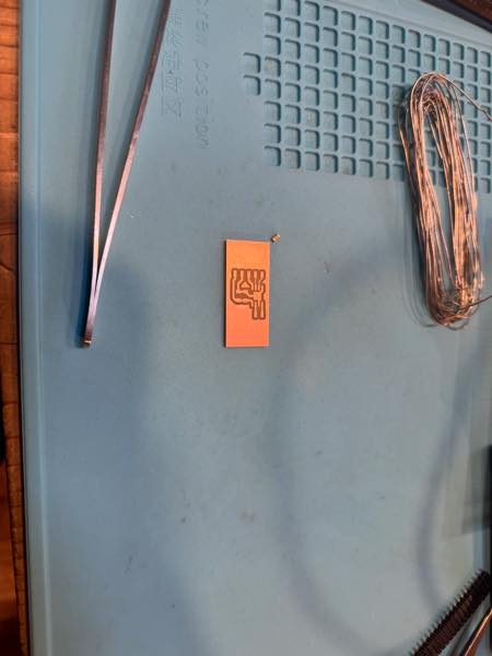
NeoPixel
![]()
I also tried using the NeoPixel/WS2812B, which will be used as a DMX output device in the final project.
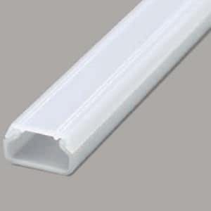
The LED tape I used this time was 1m long and 1cm wide, placed in Masaru Kogyo’s New F-Mall No. 0 1m translucent color SFM0HT (approximately 250 yen) purchased from Tomoka Electric.
 by amazon
LED pitchs 5050

If 144 LEDs are used per meter, the current consumption per LED is approximately 60mA with all RGB lights on. Converting this to power, P=I\times\ V gives $ 0.06A \times\ 5V=0.3W $ , and with 144 LEDs, this becomes 0.06 \times\ 144=8.64A, 0.3 \times\ 144=43.2W. Since the lab’s stabilized power supply had an output of up to 5A, I purchased a 5V 10A AC adapter. It cost approximately 1500 yen. (For safety, I chose a 10A power supply to operate at 80% power output.) Incidentally, with 60 LEDs per meter (a common setup), it uses approximately 3.6A (18W), while 30 LEDs per meter allows operation at 1.8A (9W).
| Wire Size (sq) | AWG (Approx.) | Allowable Current (A) |
|---|---|---|
| 0.03 sq | AWG 32 | 0.53 A |
| 0.05 sq | AWG 30 | 0.86 A |
| 0.08 sq | AWG 28 | 1.4 A |
| 0.12 sq | AWG 26 | 3 A |
| 0.2 sq | AWG 24 | 5 A |
| 0.3 sq | AWG 22 | 7 A |
| 0.5 sq | AWG 20 | 11 A |
| 0.75 sq | AWG 18 | 13 A |
| 1.25 sq | AWG 16 | 19 A |
| 2.0 sq | AWG 14 | 27 A |
| 3.5 sq | AWG 12 | 37 A |
| 4.0 sq | AWG 12 | 30 A |
| 5.0 sq | AWG 10 | 45 A |
| 5.5 sq | AWG 10 | 49 A |
| 8.0 sq | AWG 8 | 61 A |
| 14 sq | AWG 6 | 88 A |
| 22 sq | AWG 4 | 115 A |
| 38 sq | AWG 2 | 162 A |
| 60 sq | AWG | A |
| 100 sq | AWG | A |
At this point, it was 4 PM on Sunday, so to easily get it working, I decided to use the Adafruit_NeoPixel library. However, the Arduino compilation failed. The reason was that I was using an older setting for the RP2040 board.
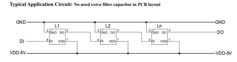 conect WS2812B by tape dataseet
5V:AC adapter
DI:RP2040 26
GND:RP2040 GND and 10A AC adapter
conect WS2812B by tape dataseet
5V:AC adapter
DI:RP2040 26
GND:RP2040 GND and 10A AC adapter
The program is this:
#include <Adafruit_NeoPixel.h>

#define PIN 26          // GP0
#define NUMPIXELS 144  // LEDpixels

Adafruit_NeoPixel strip(NUMPIXELS, PIN, NEO_GRB + NEO_KHZ800);

void setup() {
  strip.begin();
  strip.show(); // black
}

void loop() {
  // all red
  for (int i = 0; i < NUMPIXELS; i++) {
    strip.setPixelColor(i, strip.Color(255, 0, 0));
  }
  strip.show();
  delay(1000);

  // all green
  for (int i = 0; i < NUMPIXELS; i++) {
    strip.setPixelColor(i, strip.Color(0, 255, 0));
  }
  strip.show();
  delay(1000);

  // all blue
  for (int i = 0; i < NUMPIXELS; i++) {
    strip.setPixelColor(i, strip.Color(0, 0, 255));
  }
  strip.show();
  delay(1000);
}
When lighting up in rainbow colors:
#include <Adafruit_NeoPixel.h>

#define PIN 26          // GP0
#define NUMPIXELS 144  // LEDpixels

Adafruit_NeoPixel strip(NUMPIXELS, PIN, NEO_GRB + NEO_KHZ800);

void setup() {
  strip.begin();
  strip.show(); // black
}

uint32_t Wheel(byte pos) {
  if(pos < 85) {
    return strip.Color(pos * 3, 255 - pos * 3, 0);
  } else if(pos < 170) {
    pos -= 85;
    return strip.Color(255 - pos * 3, 0, pos * 3);
  } else {
    pos -= 170;
    return strip.Color(0, pos * 3, 255 - pos * 3);
  }
}

void loop() {
  static int j = 0;

  for (int i = 0; i < NUMPIXELS; i++) {
    strip.setPixelColor(i, Wheel((i + j) & 255));
  }
  strip.show();

  j++;
  delay(20);
}
Non-Zero-Crossing-SSR
In the stage lighting industry, phase control dimming is a common method for adjusting the brightness (dimming) of light bulbs that operate on 100V or 200V. In the past, dimming was achieved by switching resistors or transformer taps to compress the AC waveform. However, nowadays, semiconductors are used to segment the AC waveform for dimming, freeing us from the need for large resistors.
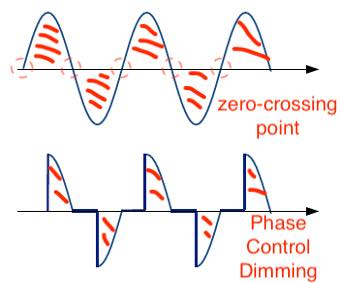
What is Phase Control Dimming?
Dimming that fails to capture the zero-crossing point
In phase control dimming, the SSR is turned OFF for a certain period from the rising edge (zero-crossing point) of the AC wave, and then turned ON midway through the wave. This effectively reduces the amount of electricity flowing. The red shaded area represents the actual amount of electrical energy flowing.
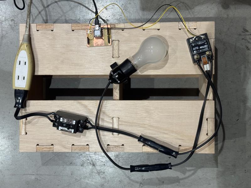
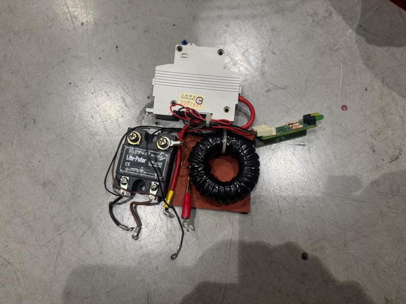
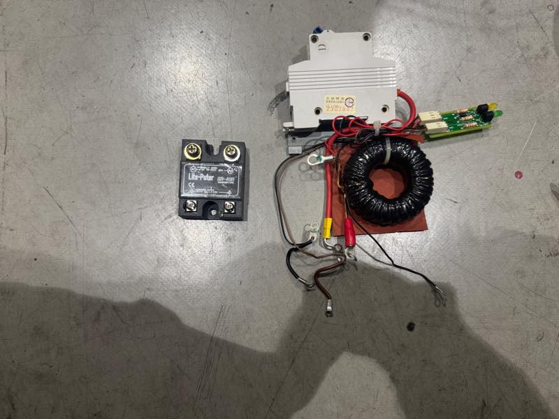
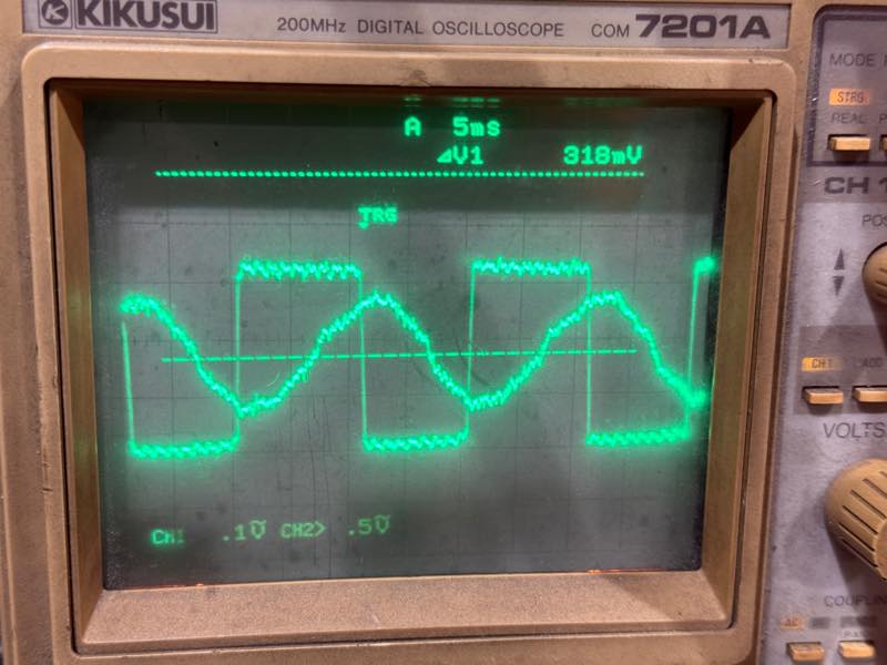
The SSR used in this project is the LITEPUTER: Solid State Relay (SSR) 40A SR-40R In P-27 This is a non-zero-crossing type. With this type, the ON timing can be easily detected by triggering it with an oscilloscope, as it turns ON in the middle of the AC waveform. In the case of a zero-crossing type (which is more commonly used), the oscilloscope shows that it turns ON when the AC waveform becomes 0V, eliminating the noise at the moment of ON. Furthermore, unlike triacs, SSRs have a built-in photocoupler for isolation, allowing for safe operation by directly connecting to a microcontroller.
SSR Operation Check
 in the dust box
 I have ssr
Since the SSR was procured from discarded equipment, an operation test was performed. The circuit is connected by inserting the SSR’s OUT into the L side of a circuit that connects an incandescent light bulb via a circuit breaker. Because the N side was also cut, the N sides are connected with a quick-connect connector.
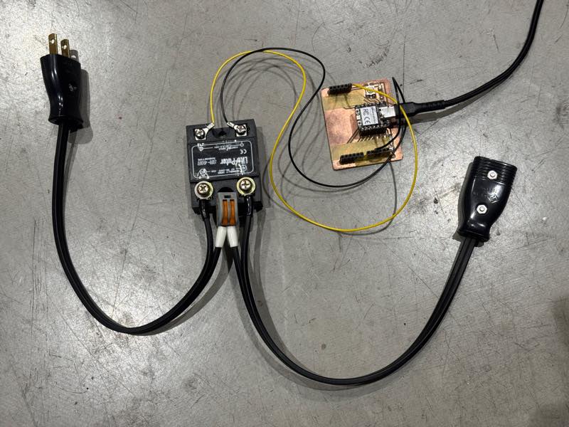
connect all circuit
The program was written to repeatedly switch between HIGH and LOW every second.
#define PIN 26

void setup() {
  pinMode(PIN,OUTPUT);
}
void loop() {
  digitalWrite(PIN,HIGH);
  delay(1000);
  digitalWrite(PIN,LOW);
  delay(1000);
}
SSR was alive!!!
The waveform at the moment of ON was checked with an oscilloscope.
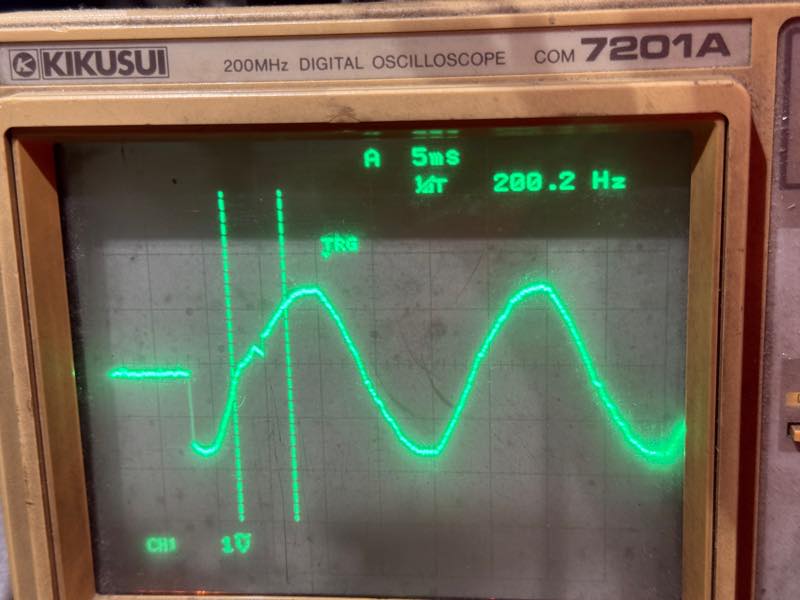
Since it turns ON midway through the waveform, it can be seen that it is a non-zero-crossing type SSR.
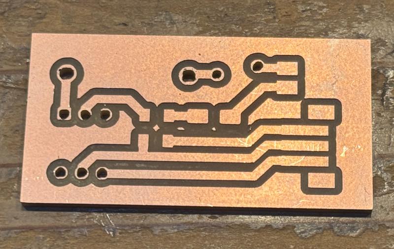
Input Zero-Crossing Circuit
The zero-crossing circuit should have been created in the input section, but it hasn’t been created yet, so only the circuit diagram is shown.
Minimum Requirements
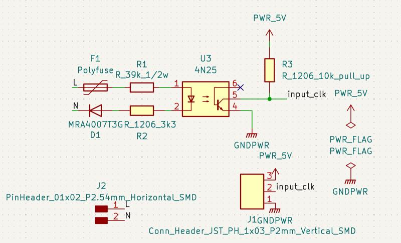
When an AC sine wave is input, the photocoupler’s LED turns ON with a slight delay, and the pulled-up circuit drops to 0V. Then, when the waveform switches from positive to negative, the photocoupler’s LED turns off with a slight delay, and the INPUT becomes the pulled-up voltage.
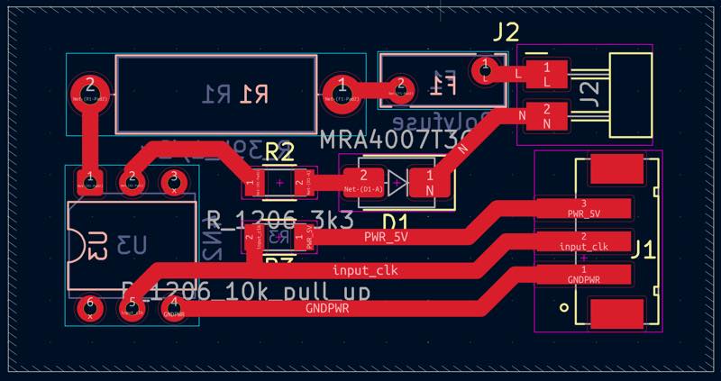
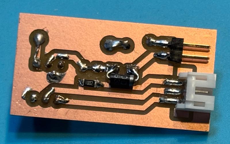
excange top to botom press kye F
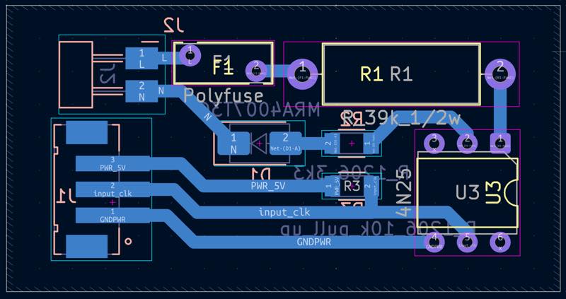
milling
makeit
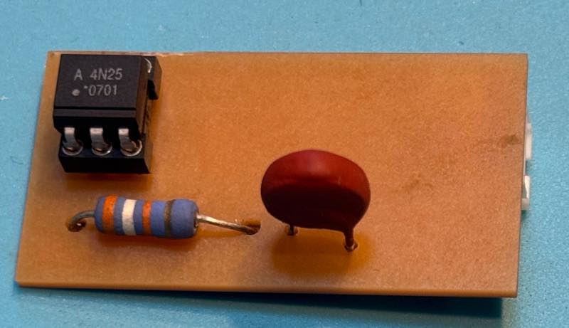
Improved Version
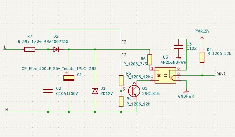
This version has been improved to remove noise from the AC waveform and to detect the zero-crossing point even when abnormal waveforms are present.
I want to use this circuit in combination with a 200V detection circuit to control dimming based on the DMX value received by the RP2040.
Furthermore, I believe the program can read the pulse sent from the zero-crossing circuit, compare it with the internal clock to calculate the frequency and zero-crossing timing, and then assign the input AC frequency to the PWM frequency based on this, changing the duty cycle ratio. I haven’t done this yet…
Special Elongated LCD
I found an LCD that seemed just right for displaying DMX512 channel signals as a bar graph.
Searching for “Majoka Iris Hack” brings up various construction articles.
 by amazon
The original toy looks like this.
by amazon
The original toy looks like this.
Disassembling it yields an LCD with a rather unusual size: 640x48 pixels. Since the width is 640 pixels, it’s possible to display one channel at a time, and it seemed usable after processing the 256 steps to 48 pixels.