16. System Integration
Assignments and Assessment this week
- Design and document the system integration for your final project
Learning outcomes
- Define and apply system integration to your final project
Have you answered these questions?
- made a plan for system integration for your final project?
- documented your plan with CAD and/or sketches for system integration?
- implemented methods of packaging? designed your final project to look like a finished product?
- documented system integration of your final project?
- linked to your system integration documentation from your final project page?
Final Project Task List
| Category | Task Description | Status |
|---|---|---|
| Device 1: Input & Output | Unit testing for all input components (Fader, Switch, Encoder) | Done |
| Verification of DMX signal output | Done | |
| Enclosure 3D printing | Done | |
| PCB design and final circuit fabrication | In Progress | |
| Final assembly and component integration | Pending | |
| Device 2: Monitoring | Basic DMX input signal verification | Done |
| TFT/LCD monitor functional testing | Pending | |
| Development of 512ch bar graph rendering engine | Pending | |
| Enclosure design and fabrication | Pending | |
| Circuit fabrication including DMX Thru port | Pending | |
| Device 3: LED Output | Basic DMX input signal verification | Done |
| Individual NeoPixel strip illumination test | Done | |
| Implementation of DMX-to-LED mapping logic | Done | |
| Enclosure design and fabrication | In Progress | |
| Final circuit fabrication and assembly | Pending | |
| Common / Review | Full system integration and stress testing | Pending |
| Graded Review meeting with instructors | Scheduled | |
| Final documentation and video demonstration | Pending |
gantt
    title Final Project Timeline (Updated: May 12)
    dateFormat  YYYY-MM-DD
    axisFormat  %m/%d
    tickInterval 1week

    section Device 1: I/O
    Unit Testing (Inputs/DMX)    :done, d1_1, 2024-04-15, 10d
    Enclosure 3D Print          :done, d1_2, 2024-04-25, 3d
    PCB Design & Fabrication     :active, d1_3, 2024-04-28, 10d
    Final Assembly               :d1_4, after d1_3, 5d

    section Device 2: Monitor
    DMX Input Verification       :done, d2_1, 2024-04-20, 5d
    TFT/LCD Functional Test      :active, d2_2, 2024-05-10, 4d
    Rendering Engine Dev         :d2_3, after d2_2, 7d
    Enclosure & Circuit Build    :d2_4, after d2_3, 7d

    section Device 3: LED
    DMX & NeoPixel Basic Test    :done, d3_1, 2024-04-25, 5d
    DMX-to-LED Mapping Logic     :done, d3_2, 2024-05-01, 7d
    Enclosure Design & Fab       :active, d3_3, 2024-05-08, 6d
    Final Circuit & Assembly     :d3_4, after d3_3, 5d

    section Common / Review
    System Integration Test      :crit, 2024-05-22, 5d
    Graded Review (Scheduled)    :milestone, 2024-05-28, 0d
    Documentation & Video Demo   :2024-05-25, 6d
    Project Completion           :milestone, 2024-05-31, 0d
System diagrams
This is the overall plan for this final project.
graph TD
    A[DMX Output Device] -- DMX Signal --> B[DMX Monitoring Device]
    B -- DMX Signal --> C[DMX Input Device]
graph TD
A[DMX Output Device] -- DMX Signal --> B[DMX Monitoring Device]
B -- DMX Signal --> C[DMX Input Device]Here are the system diagrams for each system.
Movement input & DMX output device
graph TD
    subgraph Device1 [DMX Output Device]
        %% Processing Section
        XIAO[Seeed Studio XIAO RP2040]

        %% Interface Section
        subgraph Interface [Hardware Interface]
            SF[Slide Fader] -- Analog Signal --> XIAO
            MAX485[MAX485 Transceiver]
        end

        %% Connection to Processing
        XIAO -- UART Serial --> MAX485

        %% Output Port inside Device1 but outside Interface
        Out([DMX Output Port])
        MAX485 -- DMX Signal --> Out
    end

    %% Styling
    style XIAO fill:#f96,stroke:#333,stroke-width:2px
    style MAX485 fill:#bbf,stroke:#333,stroke-width:2px
DMX signal monitoring device
graph TD
    subgraph Device_Monitor [DMX Monitoring device]
        %% Ports
        In([DMX Input Port])
        Thru([DMX Thru Port])

        %% Interface Section
        subgraph Interface [Hardware Interface]
            MAX485[MAX485 Transceiver]
            Pico[Raspberry Pi Pico RP2040]
            Graphics[Bar Graph Engine]
            Monitor[TFT/LCD Monitor]
        end

        %% Connection Flow
        In -- DMX Signal --> MAX485
        MAX485 -- DMX Signal --> Thru
        MAX485 -- UART Serial --> Pico

        %% Processing & Display
        Pico -- "Process Ch 1-512" --> Graphics
        Graphics -- Video Signal --> Monitor
    end

    %% Styling
    style Pico fill:#f96,stroke:#333,stroke-width:2px
    style MAX485 fill:#bbf,stroke:#333,stroke-width:2px
    style Monitor fill:#dfd,stroke:#333,stroke-width:2px
DMX input & Movement or lighting output device
graph TD
    subgraph Device_LED [DMX Input Device: 1 NeoPixel Strip]
        %% Input Port inside Device_LED
        In([DMX Input Port])

        %% Revised Interface Section
        subgraph Interface [Hardware Interface]
            MAX485[MAX485 Receiver]
            XIAO[Seeed Studio XIAO RP2040]
            Mapping[RGB Pixel Control Logic]
        end

        In -- DMX Signal --> MAX485
        MAX485 -- UART Serial --> XIAO
        XIAO -- "Map DMX Ch 1-432" --> Mapping

        %% Output Section
        Mapping -- One-Wire Data --> NP[NeoPixel LED Strip]

        subgraph Detail [LED Details]
            NP --- L1[LED 1: Ch 1-3]
            NP --- L2[LED 2: Ch 4-6]
            NP --- L3[LED 144: Ch 430-432]
        end
    end

    %% Styling
    style XIAO fill:#f96,stroke:#333,stroke-width:2px
    style MAX485 fill:#bbf,stroke:#333,stroke-width:2px
    style NP fill:#dfd,stroke:#333,stroke-width:2px
Movement input & DMX output device
The system I integrated this week was a movement input & DMX output device.
This enclosure was designed in Week 2 and then 3D printed at the same time 1 as the slider circuit board was created in Week 9.
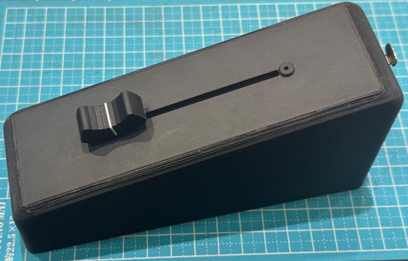
At this point, the design for the internal circuit board hadn’t been completed yet, and the slider and connector were simply attached.
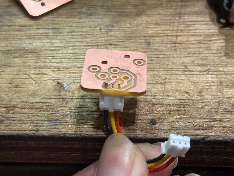
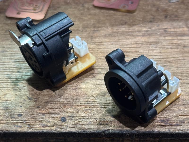
5 pin XLR PCB board
Neutrik NC5MAH NC5FAH, JST PH connectors
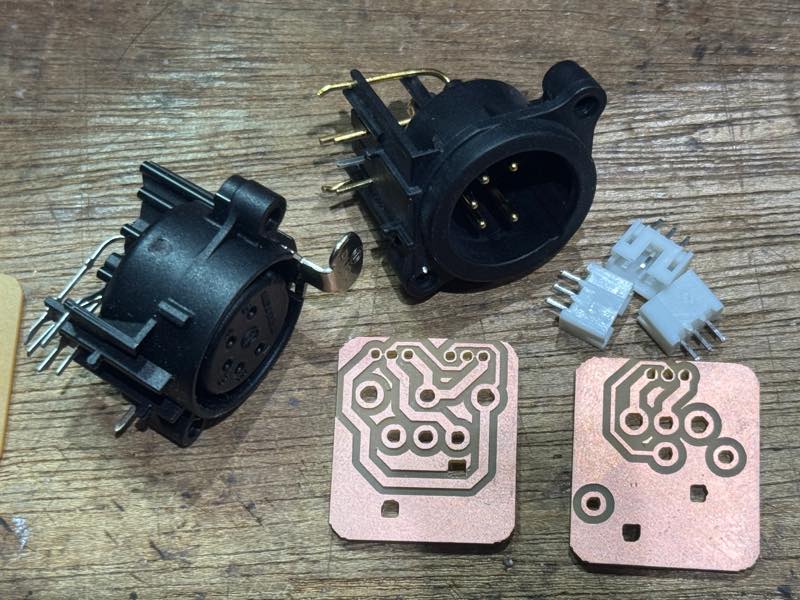
So I started by creating a circuit board for a PCB-mounted DMX connector. Internally, PH connectors are used to connect the signals, but the wiring between devices is done using 5-pin XLR connectors that conform to the DMX standard.
I attached the PH connector and soldered the posts.
The quality of the connector I bought from Amazon wasn’t very good, and I did this to prevent the plastic from melting and the pins from bending if I applied the correct amount of heat for soldering.
This is the KiCad data for the DMX connector. 2
DMX parts
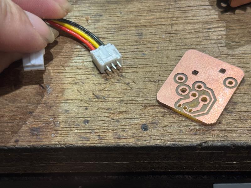
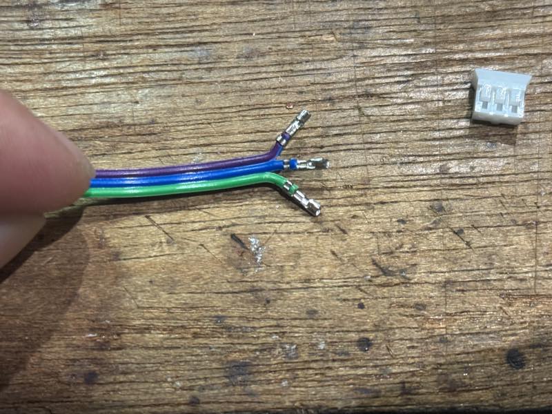
JST PH crimp connector
Crimp the PH connector.
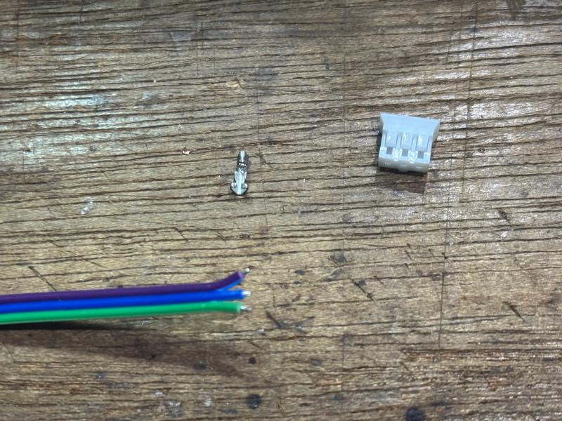
To achieve a clean crimp, using the correct crimping tool is ideal, but these are very expensive and unaffordable. However, a trick to successfully crimping with commercially available tools is to bend the back of the metal contact inward from the start; this will allow for a clean crimp.
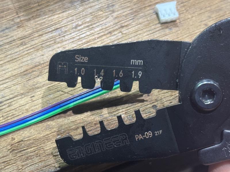
First, crimp the wires after stripping about 5mm of the wire.
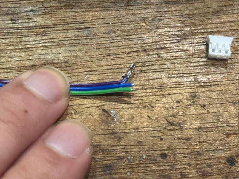
It turned out beautifully.
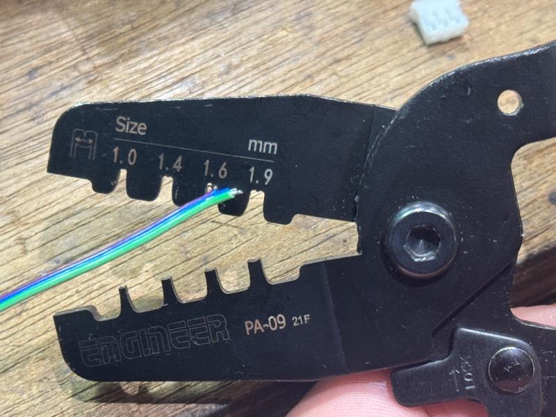
Next, use the larger crimping die next to it to crimp it so that it bites into the coating slightly.
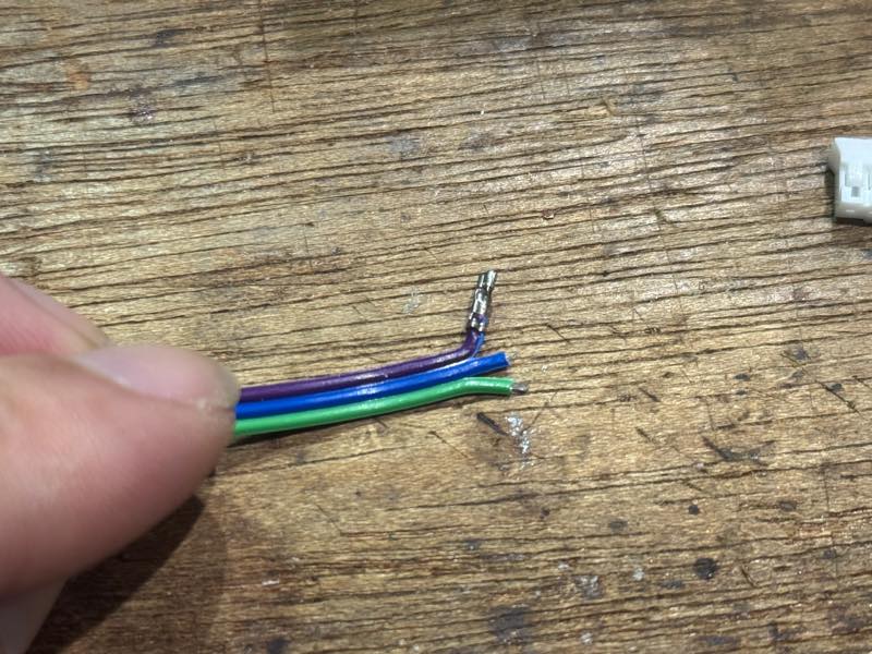
Done
Crimp all three in the same way.
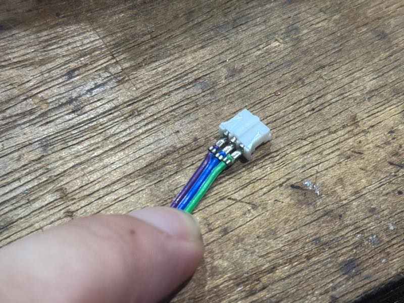
Put it into the housing
Push firmly until the part that catches goes past the tab. After this, pull on the connector and wiring to make sure they don’t come loose.
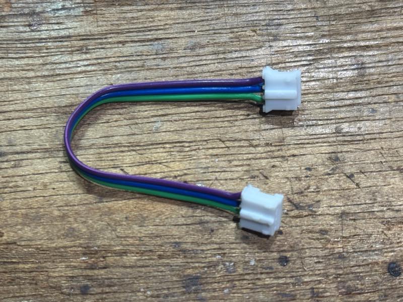
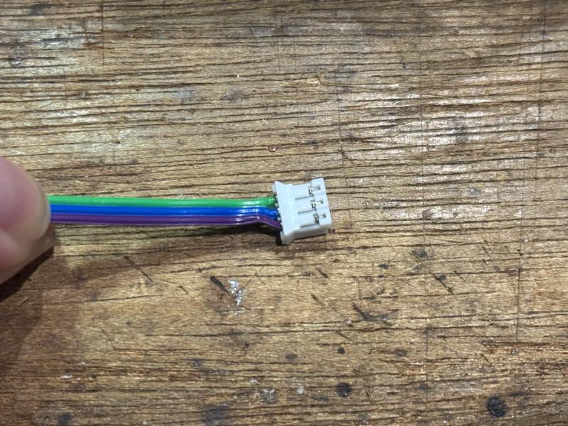
Completed
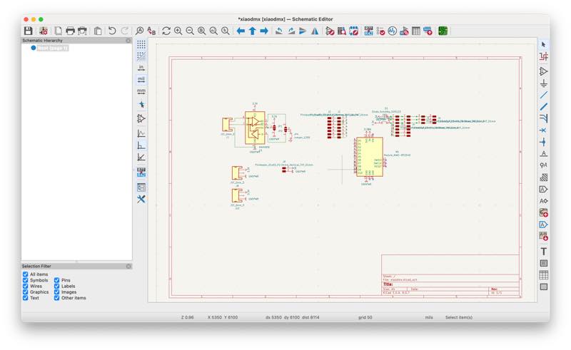
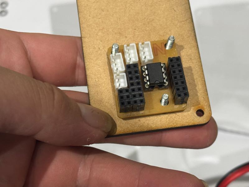
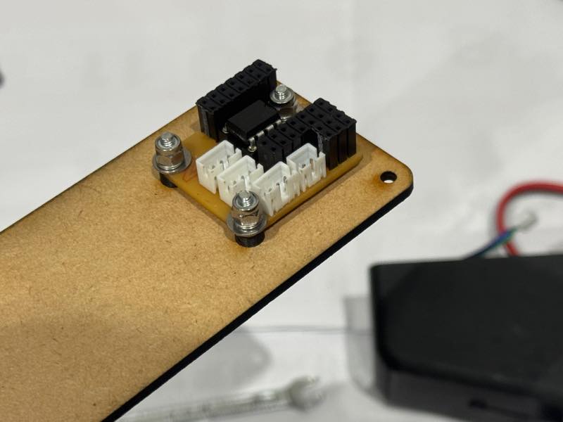
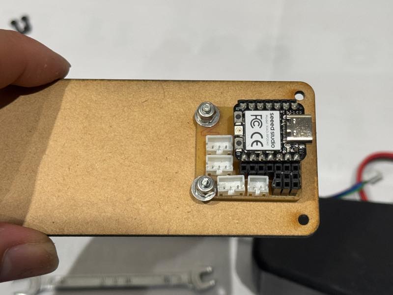
XIAO DMX Board
Schematic
PCB
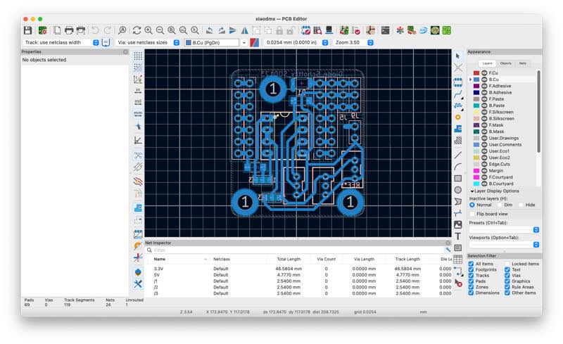
The initial circuit board was too large to fit inside, so a new board was created that combined the XIAO and RS485 chips.3
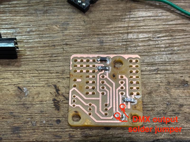
On the board during the soldering process, you can secure the DMX’s IN and OUT by using solder to jumper the parts indicated by the red circles.
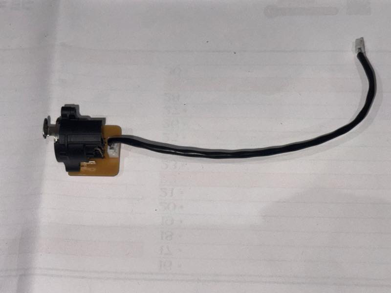
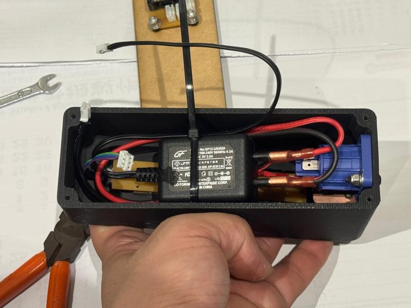
Power line
I decided to use a 5V AC adapter I bought from Akizuki Denshi as a power supply module.
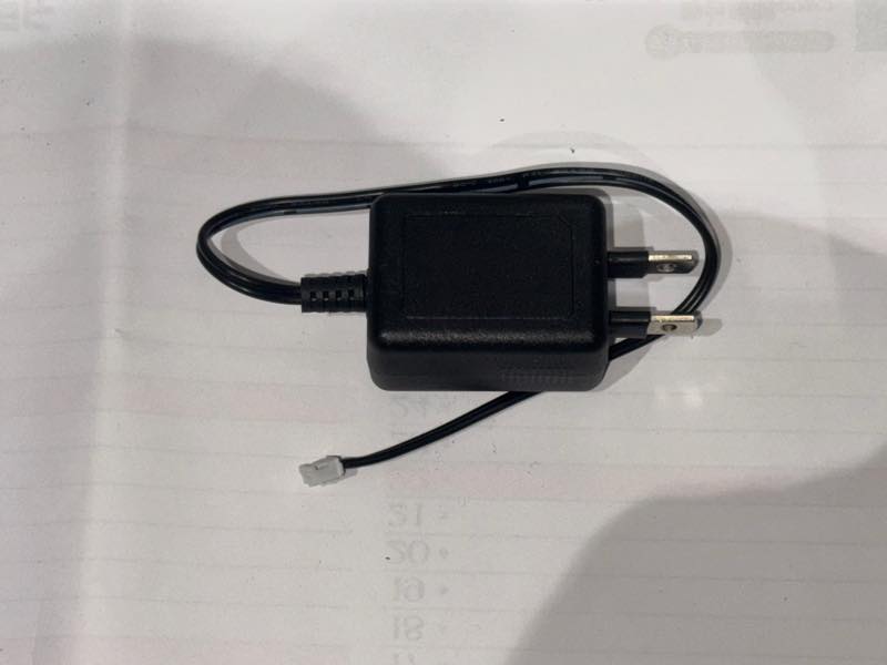
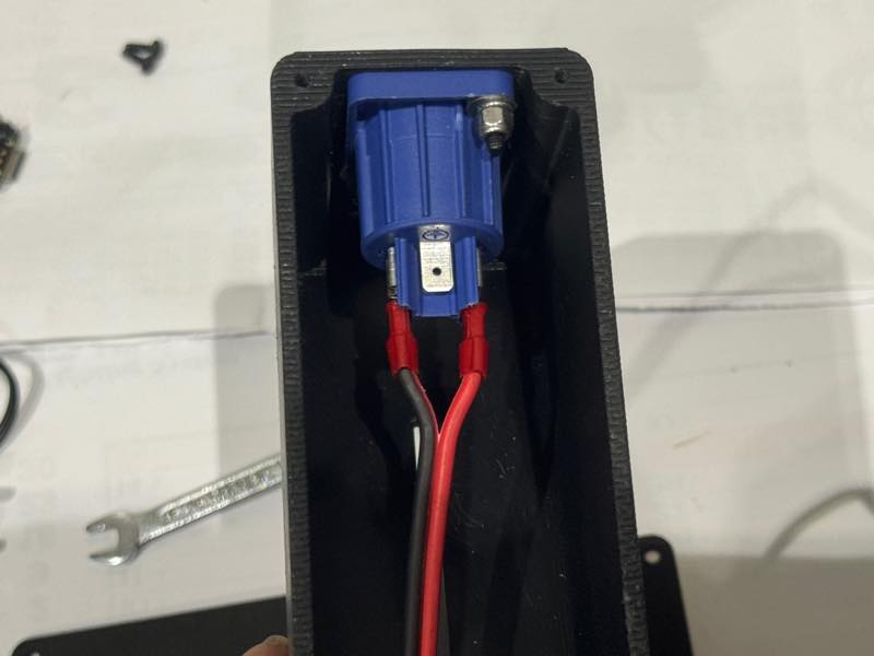
On the 5V output side, a 2-pin PH connector is attached, and on the AC side, heat shrink tubing is applied to about half of the cable, with a 250-size faston terminal attached. On the other end, a 187-size faston terminal is attached so that it can be connected to the NEUTRIK power conditioner receptacle.
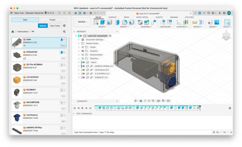
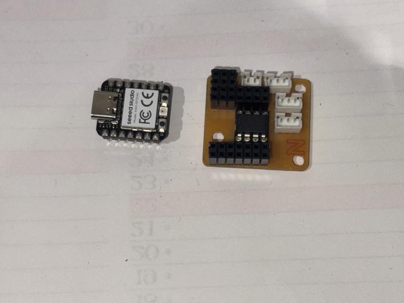
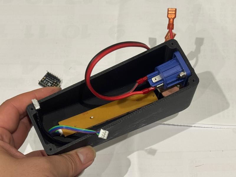
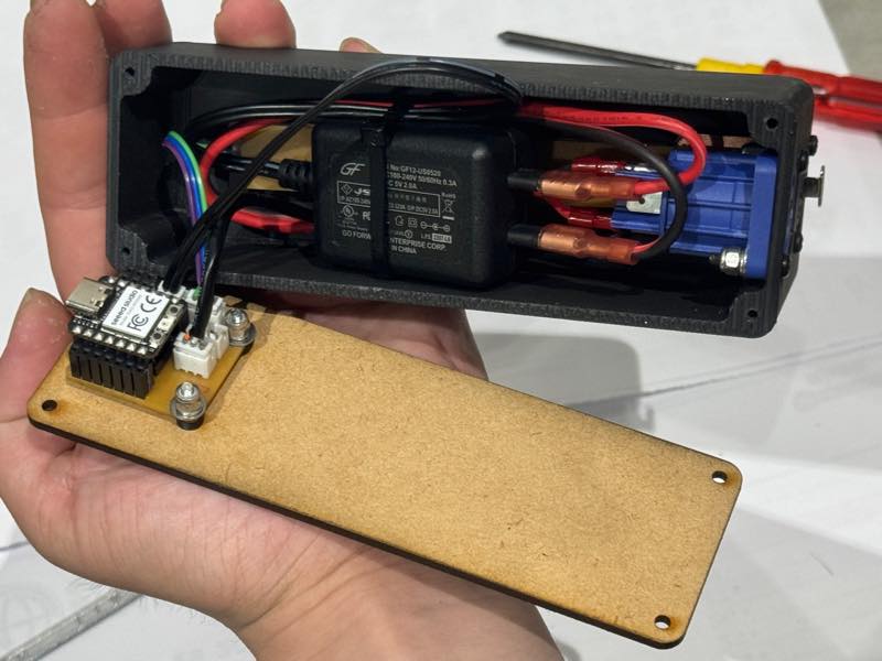
System Integration
These are all the parts that will be integrated this time.
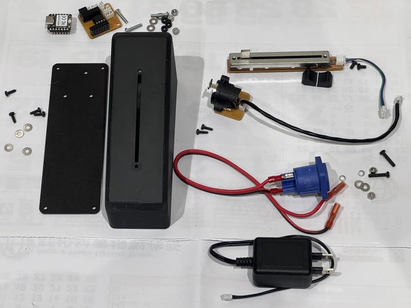
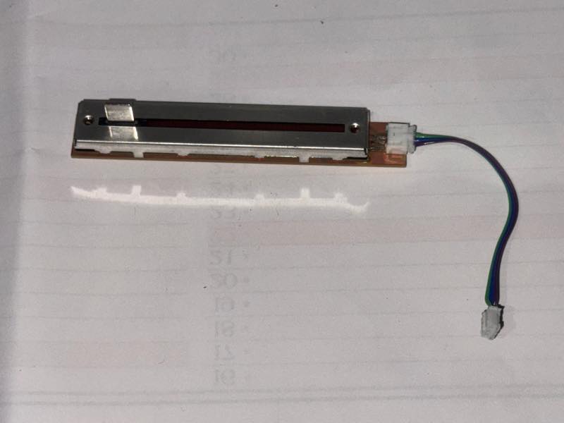
Slide volume created during week 9, the week of input devices.
XIAO RP2040 and main board The program packed inside is here4
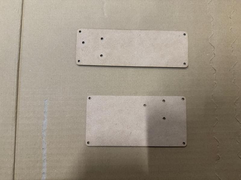
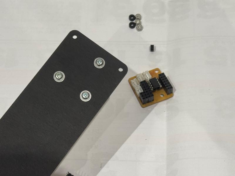
3D printed case and laser-cut bottom cover
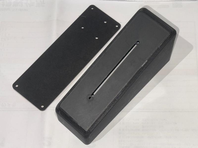
This week, I created the bottom cover using a laser cutter.5
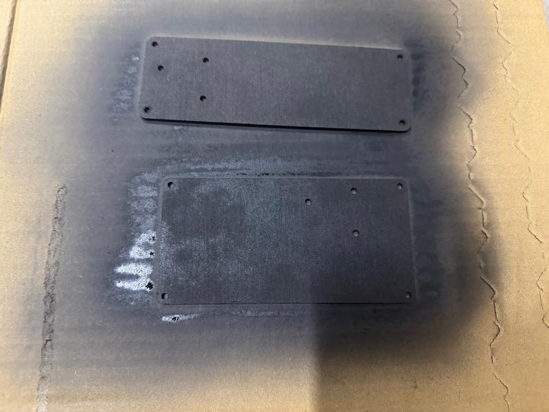
Painted black
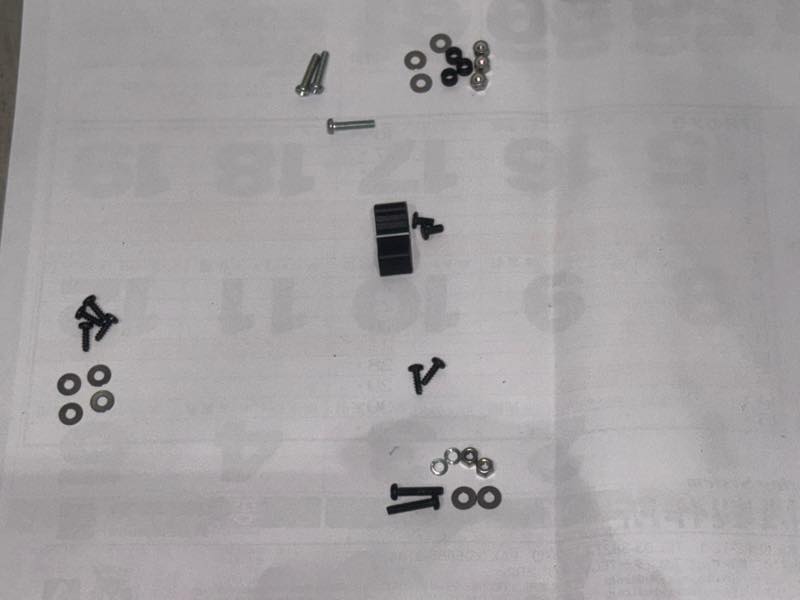
The screws that hold these in place
First, we’ll assemble the parts that attach to the 3D printed case.
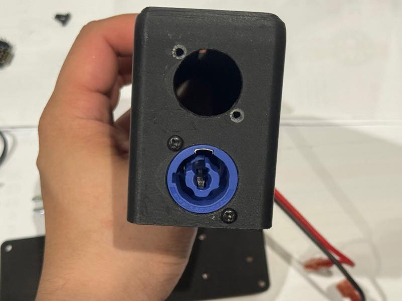
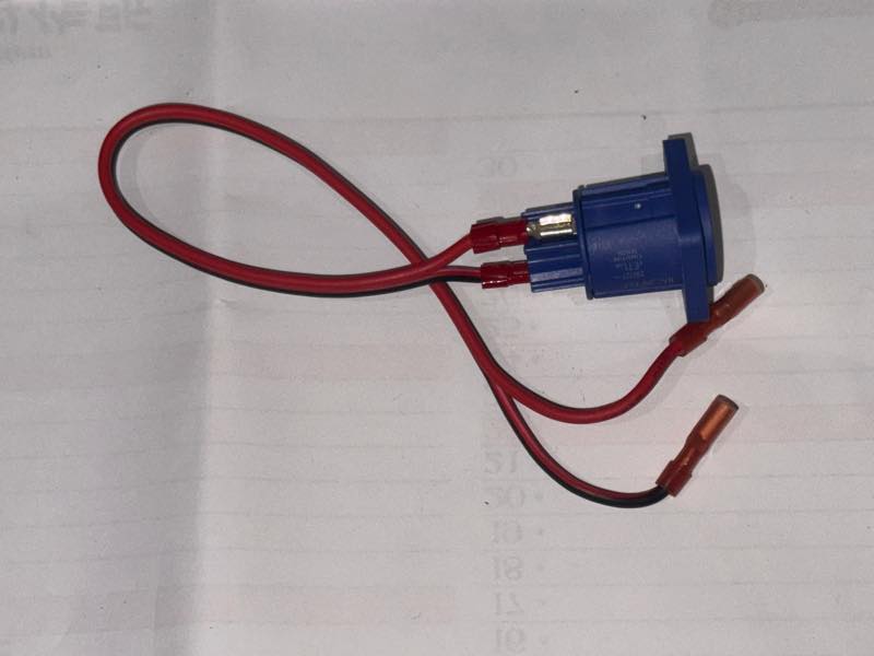
We attached the power conditioner receptacle connector.
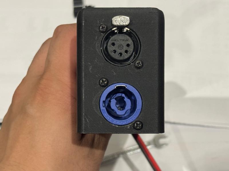
Next, I attached the DMX connector.
The AC line cable and the DMX signal cable are coming out.
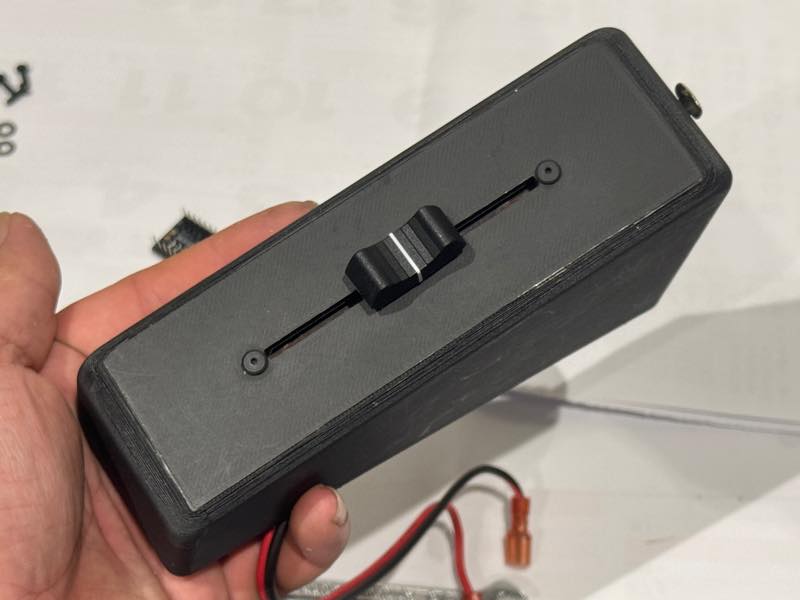
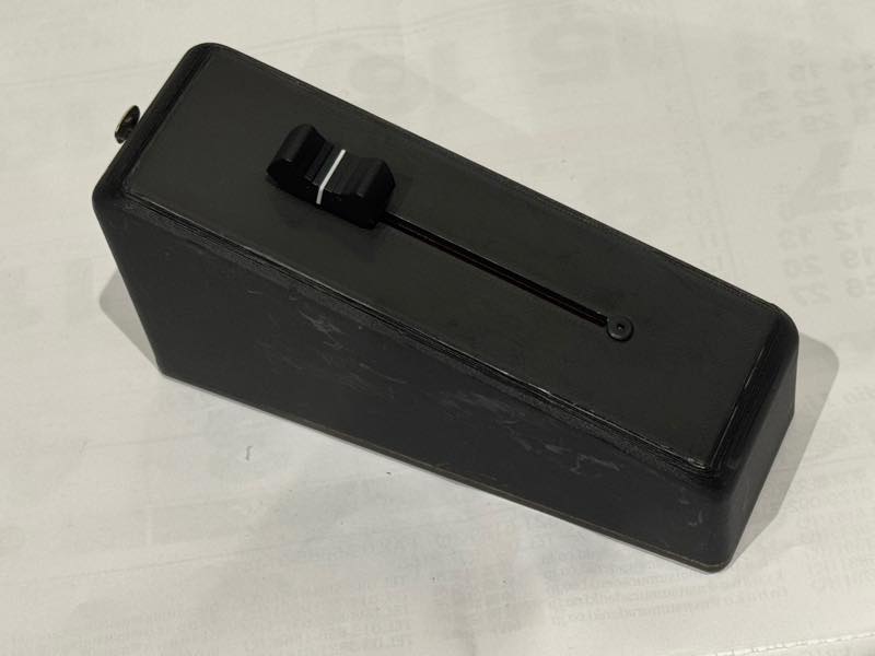
Install a slide volume control.
If you don’t use hexagonal low-profile screws to mount it, it will interfere with the fader knob.
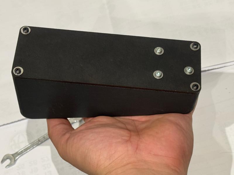
Insert the screws that attach the main circuit board to the back cover.
Insert a 3D-printed M3 spacer with a height of 3mm.
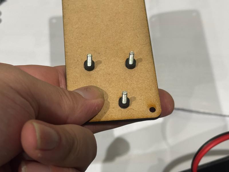
Install the main board.
I added a washer and attached it with an M3 lock nut.
Completed photo
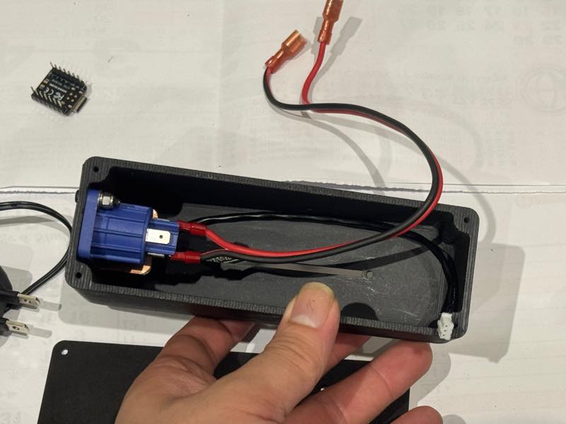
I secured the AC adapter and wiring together with cable ties to prevent them from moving.
Attach the cable to the connector.
Close the lid with screws.
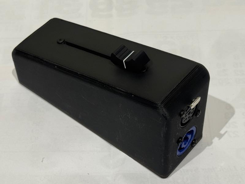
Completed
From the connector side