12. Mechanical Design, Machine Design
Assignments and Assessment this week
Mechanical Design (part 1 of 2)
Group assignment
- Design a machine that includes mechanism + actuation + automation + application
- Build the mechanical parts and operate it manually
- Document the group project
Individual assignment
- Document your individual contribution
Machine Design (part 2 of 2)
Group assignment
- Actuate and automate your machine
- Document the group project
Individual assignment
- Document your individual contribution
Learning outcomes
- Work and communicate effectively as a team
- Design, plan and build a machine
- Analyse and solve technical problems
- Recognise opportunities for improvements in the design
Have you answered these questions?
- Documented the machine building process to the group page
- Documented your individual contribution to this project on your own website
- Linked to the group page from your individual page as well as from group page to your individual pages
- Shown how your team planned, allocated tasks and executed the project (Group page)
- Described problems and how the team solved them (Group page)
- Listed possible improvements for this project (Group page)
- Included your design files (Group page)
- You need to present your machine globally and/or include a 1 min video (1920x1080 HTML5 MP4) + slide (1920x1080 PNG) (Group page)
Group Assignment
Here is a group assignment page
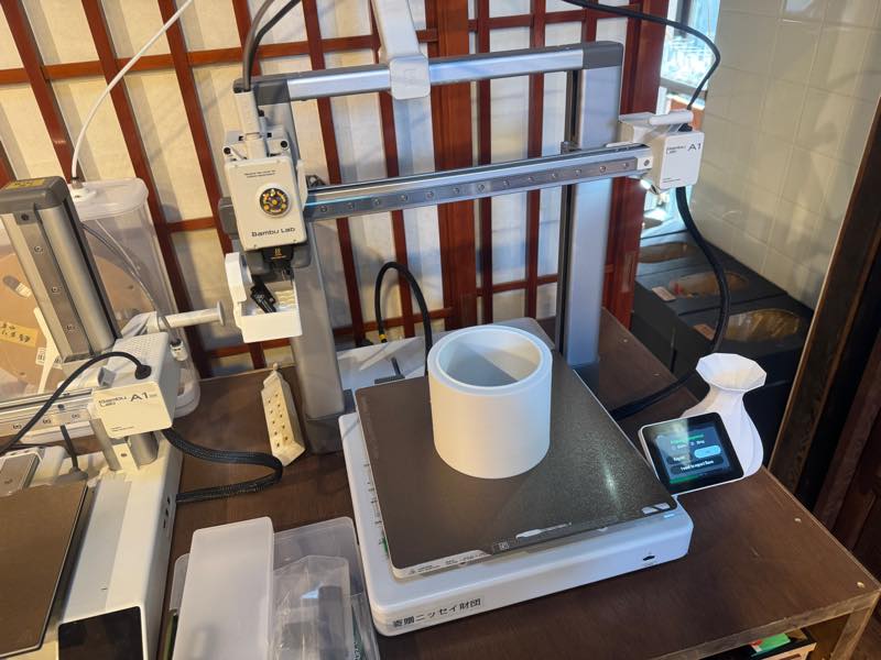
Handmade material inspection device
This week, we’re working on a project conceived by Koshi Kato (2026), with the goal of creating a homemade material inspection device that can automatically measure Young’s modulus.
Explanations of Young’s modulus and other related concepts can be found on the group page.
My design responsibilities included creating the material placement platform, the electronic components, and the program.
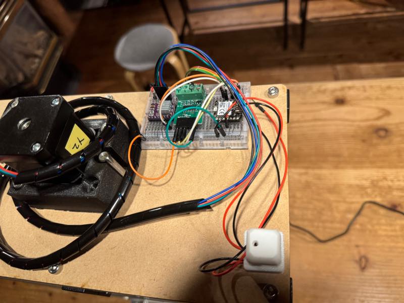
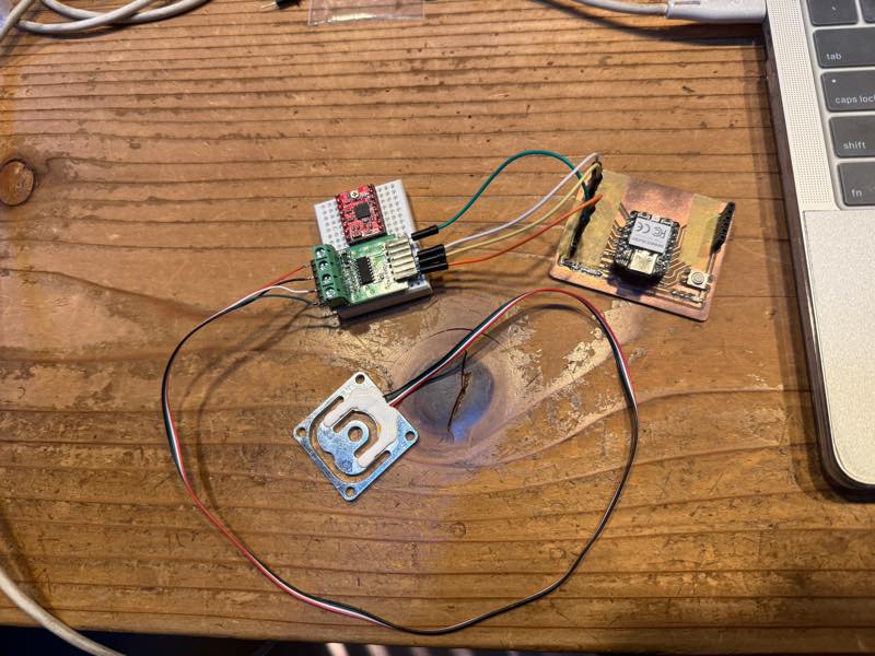
In the first week, our goal was to connect the components, get it working, and obtain measurements.
First Spiral
We decided to try modifying an onigiri machine using First Spiral.
I designed a support structure Supports Creation to hold the materials.
The completed version of First Spiral can be found on this group page.
Next, I decided to learn how to operate each of the electronic components I would be using.
Stepper motor
How to connect A4988
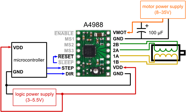
Written by mirrorn from a blog about a homemade CNC machine and laser cutter.
How to connect DRV8825
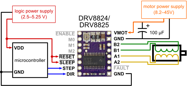
Written by mirrorn from a blog about a homemade CNC machine and laser cutter.
First, I did the wiring and programmed the servo motor to work.
Using the Arduino library AccelStepper
#include <AccelStepper.h>


const int  INTERFACE_TYPE = 1;
const byte STEP_PIN       = D5;
const byte DIR_PIN        = D4;


const float MOVE_SPEED    = 2000;

AccelStepper Xaxis(INTERFACE_TYPE, STEP_PIN, DIR_PIN);

void setup() {

  Xaxis.setMaxSpeed(10000);
  Xaxis.setSpeed(MOVE_SPEED);
}

void loop() {

  Xaxis.runSpeed();
}
Minimum distance traveled relative to the rotation step of the lead screw
Screw pitch=2mm Screw lead=1 It moves 2mm per rotation.
A NEMA17 motor rotates once every 200 pulses.
The DRV8825 has \frac{1}{32} microstepping, a maximum voltage of 45V, and a rated current of 1.5A (maximum 2.5A).
Minimum distance traveled \frac{2}{200} \times 32
Load cell & HX711 AD converter
A load cell uses a strain gauge, a sensor that changes resistance when force is applied to a metal, to detect even slight deformations in the metal and output the result as a change in resistance. However, this output is a very small value and cannot be seen without signal amplification. By passing the signal through a module called the HX711, which combines an amplifier circuit and an analog-to-digital converter (AD converter), the microcontroller can easily read the output as 24 bits.
Using the HX711 from the Arduino library
#include "HX711.h"

// HX711 circuit wiring
const int LOADCELL_DOUT_PIN = D9;
const int LOADCELL_SCK_PIN = D8;

HX711 scale;

void setup() {
  Serial.begin(115200);
  scale.begin(LOADCELL_DOUT_PIN, LOADCELL_SCK_PIN);
}

void loop() {

  if (scale.is_ready()) {
    int reading = scale.read();

    //Serial.print("HX711_reading ");
    //Serial.print(",");
    Serial.println(reading);
    //Serial.println(",");

  } else {
    Serial.println("HX711 not found.");
  }

  delay(100);

}
Program Design Plan
Press switch
L start
| Lpless unit down
| L Load Cell touch
| L pless unit up
| L pless unit Slow down
| L Load Cell touch
| L pless unit stop
| L start meguaring Young’s Modulus
| L pless unit Slow down
| L serial print text to csv
| L Load Cell not pressing
| L Finish meguaring
| L pless unit up to start point
| L sleep
|
L Elce sleep
I’ve decided to have ChatGP organize the rough outline of this program’s operation into a more visually appealing diagram.
Please output a flowchart and sequence diagram in a format that can be directly used with Markdown, based on this rough program design.
Flowchart
graph TD
    Start([1. Press Switch Start]) --> Down1[2. Press Unit Down <br>Fast Approach]
    Down1 --> Touch1{3. Load Cell Touch? <br>First Contact}
    Touch1 -- Yes --> Up1[4. Press Unit Up <br>Slight Retraction]
    Up1 --> SlowDown1[5. Press Unit Slow Down <br>Precision Approach]
    SlowDown1 --> Touch2{6. Load Cell Touch? <br>Measurement Origin}
    Touch2 -- Yes --> Stop1[7. Press Unit Stop <br>Temporary Stop]
    Stop1 --> Measure[8. Start Measuring <br>Young's Modulus]
    Measure --> SlowDown2[9. Press Unit Slow Down <br>Controlled Pressing]
    SlowDown2 --> CSV[10. Serial Print Text to CSV <br>Data Export]
    CSV --> NotPressing{11. Load Cell Not Pressing? <br>Unloading Check}
    NotPressing -- Yes --> Finish[12. Finish Measuring]
    Finish --> Return[13. Press Unit Up to Start Point <br>Home Position]
    Return --> Sleep[14. Sleep / Else Sleep <br>Standby Mode]
Sequence Diagram
sequenceDiagram
    autonumber
    actor User as Operator / Host System
    participant Ctrl as Controller
    participant Press as Press Unit
    participant LC as Load Cell

    User->>Ctrl: press switch start
    Ctrl->>Press: unit down (Fast Approach)
    LC-->>Ctrl: load cell touch (First Contact)
    Ctrl->>Press: unit up (Slight Retraction)

    Ctrl->>Press: unit slow down (Precision Approach)
    LC-->>Ctrl: load cell touch (Measurement Origin)
    Ctrl->>Press: unit stop

    Ctrl->>Ctrl: start measuring young's modulus
    Ctrl->>Press: unit slow down (Controlled Pressing)
    Ctrl->>User: serial print text to csv

    LC-->>Ctrl: load cell not pressing (Unloaded)
    Ctrl->>Ctrl: finish measuring
    Ctrl->>Press: unit up to start point (Return Home)
    Ctrl->>Ctrl: sleep / else sleep (Standby)
Although we were unable to implement all the functions shown in this diagram, we were able to implement the operation of the press unit descending, taking measurements, and returning to its initial position.
Programs
First, I simply combined the two and tried to control them with a switch.
#include <AccelStepper.h>
#include "HX711.h"

// Pin configuration
const int INTERFACE_TYPE = 1;
const int STEP_PIN       = 2;
const int DIR_PIN        = 5;

const int BUTTON_PIN     = 3;

const int LOADCELL_DOUT  = 9;
const int LOADCELL_SCK   = 8;

// Parameters
const long  THRESHOLD     = 50000;// Test you are loadcell
const int   STEPS_PER_REV = 6400; // Total pulses for 1 rotation (1/32 step)
const int   BACK_REV      = 5;    // Reversal amount (rotations)
const float MOVE_SPEED    = 2000.0;

AccelStepper Xaxis(INTERFACE_TYPE, STEP_PIN, DIR_PIN);
HX711 scale;

// Control state machine
enum State { WAIT_BUTTON, MOVING, REVERSING };
State currentState = WAIT_BUTTON;

void setup() {
  Serial.begin(115200);
  pinMode(BUTTON_PIN, INPUT_PULLUP); // Button between pin 3 and GND
  scale.begin(LOADCELL_DOUT, LOADCELL_SCK);

  Xaxis.setMaxSpeed(12800);
  Xaxis.setAcceleration(5000);
  Xaxis.setMinPulseWidth(2); // For RP2040 high speed stability
}

void loop() {
  switch (currentState) {
    case WAIT_BUTTON:
      // Start sequence on button press
      if (digitalRead(BUTTON_PIN) == LOW) {
        delay(200); // Debounce
        Xaxis.setSpeed(MOVE_SPEED);
        currentState = MOVING;
      }
      break;

    case MOVING:
      // Constant speed rotation
      Xaxis.runSpeed();

      // Load cell trigger check
      if (scale.is_ready() && scale.read() > THRESHOLD) {
        // Calculate 5-rev reverse target from current position
        long target = Xaxis.currentPosition() - (long)(STEPS_PER_REV * BACK_REV);
        Xaxis.moveTo(target);
        currentState = REVERSING;
      }
      break;

    case REVERSING:
      // Move with acceleration to target
      if (Xaxis.distanceToGo() != 0) {
        Xaxis.run();
      } else {
        // Sequence finished
        currentState = WAIT_BUTTON;
      }
      break;
  }
}
#include <AccelStepper.h>
#include "HX711.h"

const int INTERFACE_TYPE = 1;
const int STEP_PIN       = D9;
const int DIR_PIN        = D8;

const int BUTTON_PIN     = D10;

const int LOADCELL_DOUT  = D4;
const int LOADCELL_SCK   = D5;

const long  THRESHOLD      = 50000;
const int   STEPS_PER_REV  = 6400;
const int   BACK_REV       = 5;
const float MOVE_SPEED     = 2000.0;
const float SLOW_SPEED     = 500.0;
const float SCREW_PITCH    = 2.0;

AccelStepper Xaxis(INTERFACE_TYPE, STEP_PIN, DIR_PIN);
HX711 scale;

enum State { WAIT_BUTTON, MOVING, REVERSING, REPROACH, MEASURING };
State currentState = WAIT_BUTTON;

long zeroStepPos = 0;
long lastLoad    = 0;

void setup() {
  Serial.begin(115200);
  pinMode(BUTTON_PIN, INPUT_PULLUP);
  scale.begin(LOADCELL_DOUT, LOADCELL_SCK);
  Xaxis.setMaxSpeed(12800);
  Xaxis.setAcceleration(5000);
  Xaxis.setMinPulseWidth(2);
}

void loop() {
  long currentLoad = scale.is_ready() ? scale.read() : 0;

  switch (currentState) {
    case WAIT_BUTTON:
      if (digitalRead(BUTTON_PIN) == LOW) {
        delay(200);
        Xaxis.setSpeed(MOVE_SPEED);
        currentState = MOVING;
      }
      break;

    case MOVING:
      Xaxis.runSpeed();
      if (currentLoad > THRESHOLD) {
        Xaxis.moveTo(Xaxis.currentPosition() - (long)(STEPS_PER_REV * BACK_REV));
        currentState = REVERSING;
      }
      break;

    case REVERSING:
      if (Xaxis.distanceToGo() != 0) {
        Xaxis.run();
      } else {
        Xaxis.setSpeed(SLOW_SPEED);
        currentState = REPROACH;
      }
      break;

    case REPROACH:
      Xaxis.runSpeed();
      if (currentLoad > THRESHOLD) {
        zeroStepPos = Xaxis.currentPosition();
        lastLoad = currentLoad;
        currentState = MEASURING;
      }
      break;

    case MEASURING:
      Xaxis.runSpeed();
      float distance = (Xaxis.currentPosition() - zeroStepPos) * (SCREW_PITCH / (float)STEPS_PER_REV);

      Serial.print(distance, 4);
      Serial.print(",");
      Serial.println(currentLoad);

      if (currentLoad < lastLoad) {
        Xaxis.setSpeed(0);
        currentState = WAIT_BUTTON;
      }
      lastLoad = currentLoad;
      break;
  }
}
It is not working programs because the sensor readings were interfering with the motor’s movement. However, we wanted to read the sensor readings as precisely as possible.
As a solution, our instructor,Kae Nagano (2019), offered a good suggestion.
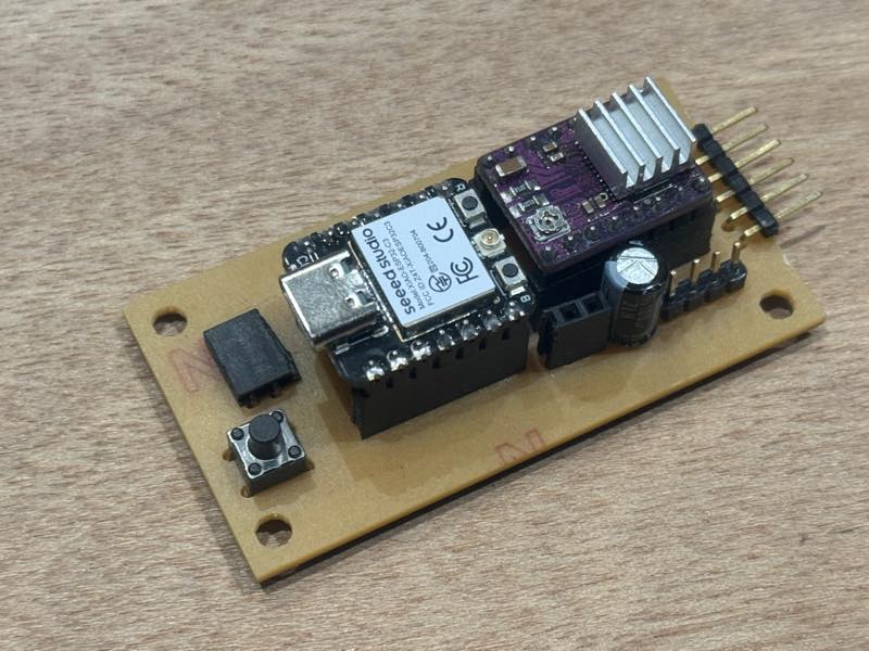
Since our microcontroller was an RP2040, we used a second core (setup 1, loop 1) and created a program that constantly measured force and distance while activating the motor when a button was pressed.
// The normal, core0 setup
#include <AccelStepper.h>
#include "HX711.h"

const int INTERFACE_TYPE = 1;
const int STEP_PIN = D5;
const int DIR_PIN = D4;

const int LOADCELL_DOUT_PIN = D1;
const int LOADCELL_SCK_PIN = D0;
long HX711_reading = 0;
int sensorValue = 0;

const int analogInPin = A2;

int switch_status = 1;
int machine_status = 0;
int Inverted_status = 1;
const int SW_PIN = D10;

const float MOVE_SPEED = 5000;
HX711 scale;

AccelStepper Xaxis(INTERFACE_TYPE, STEP_PIN, DIR_PIN);

void setup() {
  pinMode(SW_PIN,INPUT_PULLUP);
  Xaxis.setMaxSpeed(10000);
  Xaxis.setSpeed(MOVE_SPEED);
  Serial.begin(115200);
}

void loop() {
  int current_switch = digitalRead(SW_PIN);
  //Serial.println(current_switch);
  // switch was plessd
  if (current_switch != switch_status && current_switch == LOW) {
    if (machine_status == 0) {
      machine_status = 1;
      Inverted_status = 1;
    } else {
      machine_status = 0;
      Inverted_status = -1;
    }

    Serial.print("machine_status = ");
    Serial.print(machine_status);
    Serial.print("  SW = ");
    Serial.println(current_switch);

    delay(200);
  }

  // moveing moter
  if (machine_status == 1) {

    //Serial.println(machine_status);
    //for(int i=0;i<100;i++){
    Xaxis.runSpeed();
    //}
  }else{
    Xaxis.disableOutputs();
  }

  switch_status = current_switch;
}

// Running on core1

void setup1() {
  Serial.begin(115200);
  scale.begin(LOADCELL_DOUT_PIN, LOADCELL_SCK_PIN);
}

void loop1() {

  if (scale.is_ready()) {
    HX711_reading = scale.read();
    sensorValue = analogRead(analogInPin);
    Serial.print(600);
    Serial.print(",");
    Serial.print(sensorValue);
    Serial.print(",");
    Serial.println(HX711_reading);
    //Serial.println(",");

  } else {
    Serial.println("HX711 not found.");
  }

  delay(100);

}
Even with this program, the motor’s movement was still erratic. Ultimately, we sent the motor movement part to the AI Gemini for verification.
The prompt I gave to Gemini is the following quoted section:
The motor movement in this program is erratic. In this program, when the switch is pressed, the motor rotates, and based on the data measured in Loop 1 of another core, if a certain threshold is exceeded, the motor stops and reverses rotation. The switch should start the motor when it is not operating, and stop the motor when it is operating, regardless of whether it is moving forward or backward.
The program that Gemini returned from this prompt is the following program.
#include <AccelStepper.h>
#include "HX711.h"

// Pin settings
const int INTERFACE_TYPE = 1;
const int STEP_PIN = D5;
const int DIR_PIN = D4;
const int LOADCELL_DOUT_PIN = D1;
const int LOADCELL_SCK_PIN = D0;
const int SW_PIN = D10;
const int analogInPin = A2;

// Variables
long HX711_reading = 0;
int sensorValue = 0;
int switch_status = 1;
int machine_status = 0; // 0:Idle, 1:Forward(Down), 2:Reverse(Up)

// Custom settings
const long THRESHOLD = 250000;
const float MOVE_SPEED = 10000;   // Forward speed
const float ESCAPE_SPEED = 5000;  // Reverse speed

HX711 scale;
AccelStepper Xaxis(INTERFACE_TYPE, STEP_PIN, DIR_PIN);

void setup() {
  pinMode(SW_PIN, INPUT_PULLUP);
  Xaxis.setMaxSpeed(10000);
  Serial.begin(115200);
}

void loop() {
  int current_switch = digitalRead(SW_PIN);

  // --- 1. Switch Control ---
  if (current_switch != switch_status && current_switch == LOW) {
    if (machine_status == 0) {
      machine_status = 1; // Start movement
      Xaxis.setSpeed(MOVE_SPEED);
      Serial.println("START: FORWARD");
    } else {
      machine_status = 0; // Stop movement
      Xaxis.stop();
      Xaxis.disableOutputs();
      Serial.println("STOP: BY SWITCH");
    }
    delay(200); // Debounce
  }
  switch_status = current_switch;

  // --- 2. Motor Logic ---
  if (machine_status == 1) {
    // Forward mode: check for overload
    if (HX711_reading < -THRESHOLD) {
      machine_status = 2; // Auto-reverse
      Xaxis.setSpeed(-ESCAPE_SPEED);
      Serial.println("!!! OVERLOAD: REVERSING !!!");
    } else {
      Xaxis.runSpeed();
    }
  }
  else if (machine_status == 2) {
    // Reverse mode: keep moving back
    Xaxis.runSpeed();
  }
  else {
    // Stop mode
    Xaxis.disableOutputs();
  }
}

// --- Data Acquisition (Core 1) ---
void setup1() {
  scale.begin(LOADCELL_DOUT_PIN, LOADCELL_SCK_PIN);
}

void loop1() {
  if (scale.is_ready()) {
    HX711_reading = scale.read();
    sensorValue = analogRead(analogInPin);

    // Print data for Serial Plotter
    Serial.print(600);
    Serial.print(",");
    Serial.print(sensorValue);
    Serial.print(",");
    Serial.println(HX711_reading);
  }
  delay(100);
}
This final program allows the motor to be started and stopped by a switch, and the movement to reverse and ascend based on the load cell value. Furthermore, previous experiments showed that bending the bamboo was difficult due to insufficient torque at slow motor rotation speeds, so the speed can now be adjusted using MOVE_SPEED: 10000 and ESCAPE_SPEED: 5000. The distance traveled was achieved by recording the change in resistance value (analogInPin = A2) due to the rotation of a potentiometer, as suggested by Koushi-san. The load cell and potentiometer values are routed in a separate loop using Loop 1 to eliminate their influence on the motor’s rotation.
Here’s the video of the measurement.
The change in the potentiometer value was too small to be clearly visible on the graph, but it was definitely changing.
Failed circuit board manufacturing
I tried to create a PCB from a circuit I built on a breadboard. However, I accidentally flipped a component by pressing the F key on the keyboard during the PCB layout process, which seemed to have disrupted the circuit’s alignment. I learned that when creating a circuit on the back side in KiCad, selecting the back layer (blue) and drawing the circuit transparently from the front side works well.
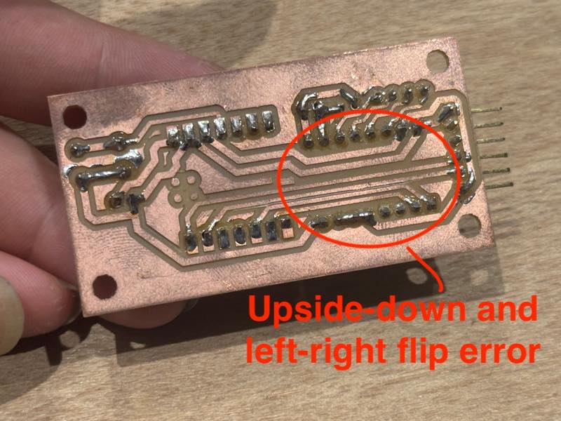
Due to time constraints, I had to postpone manufacturing the corrected PCB and temporarily test the circuit on the breadboard.