Week 11: Machine Design
The main outcomes for the week
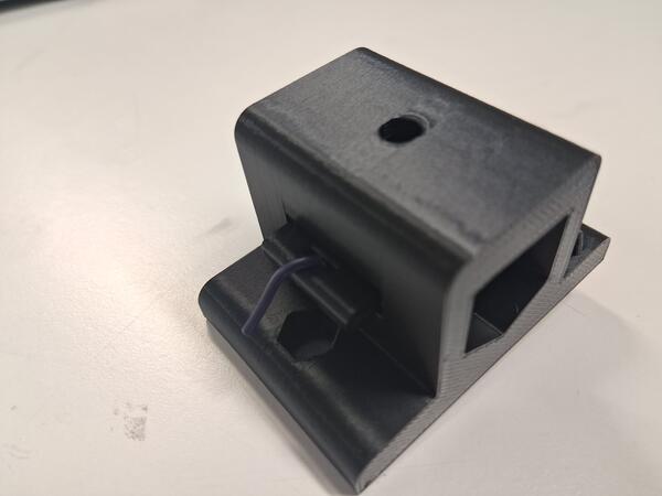
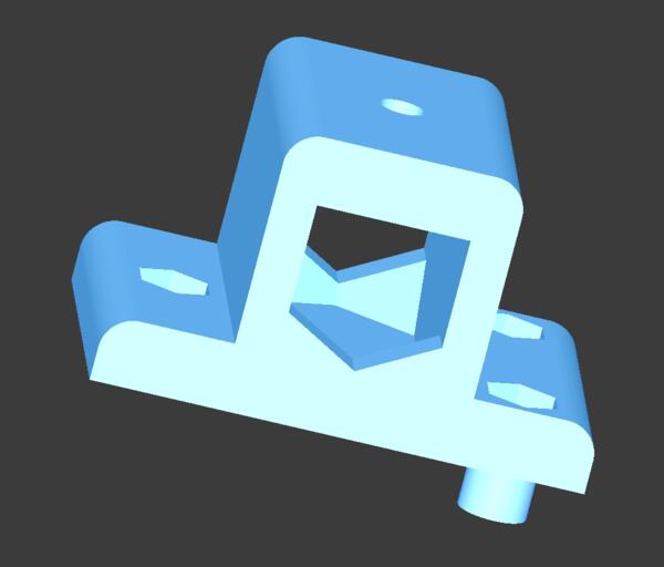
I rethought, designed, 3D printed and assembled a more usable (?) tool holder for Blot plotting machine:
Design files made in these week are available at my gitlab repository
Group assignment
This week was about collaborative machine design project. I was in Istanbul and met with people at Fab Lab Hisar. However, I was somewhat sick most of the time so we were working together at the lab for only in one day. Our project was a replication of a machine plotter Blot by Hackclub. Our group assignment page can be found here. Here in my own documentation page I document my contribution to the whole: setting up the group assignment project on Gitlab, publishing the documentation, and redesigning the tool/pen holder piece of the machine.
Setting up the group page
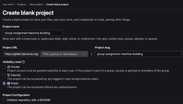
At my Gitlab account I created a new public repository without Readme file.
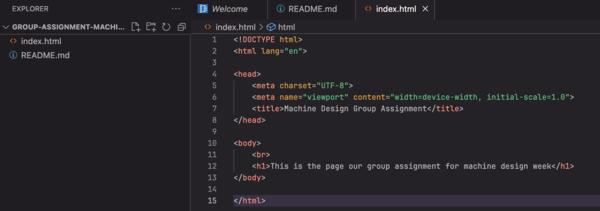
I opened the repository in Web IDE and created README.md, in which I copy pasted the group assignment, and index.html, which I later moved to a new directory named public. These were just basic skeletons to add content as the assignment goes on. Then I commited and pushed to main.
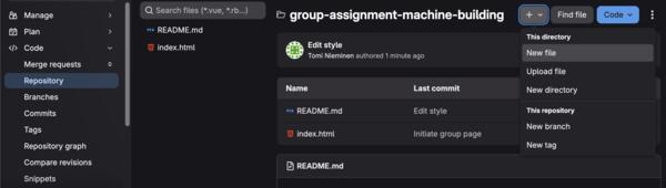
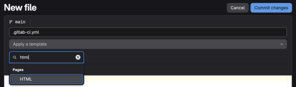
In the project main page, I created a new file which I named .gitlab-ci.yml which gives instructions on how the page is published.
After writing the name, a field Add a template became visible: on it I selected HTML and the content for the file became as below.
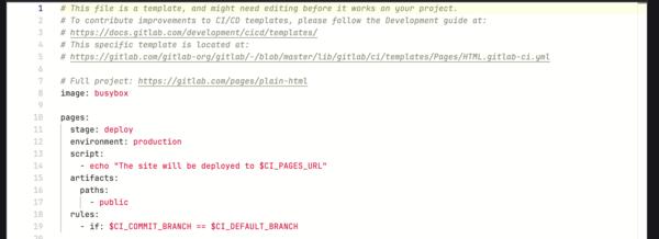
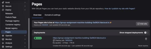
Then I committed changes. At Deploy > Pages I was now able to see that the page was published in the given URL.
At the project's Gitlab main page, I invited other members of the group to the project based on their Gitlab account names or emails if not found.
Styling the page with AI
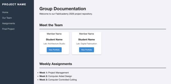
Continuing to style the page a bit more I asked Gemini Pro: “Hi, could you provide me html and css templates for a group assignment to fill in content of our project, similar to other documentation pages done in FabAcademy: https://fabacademy.org/2026/people.html?”
The outcome looked liked this:
I further prompted: “Actually, can you provide html and css files for just a one page of documentation for a single week, similar to most original (ie. not template based) documentation pages in https://fabacademy.org/2026/people.html?” The outcome looked liked this, with the page margins inconsistent:
I asked to: “Can you make the margins consistent across the whole page? Also add a frame for adding images on the page as well, thanks.” Now the result was with consistent margins but it was still quite plain with the styling.
I also tried the same first prompt with Claude’s free version, and the result looked much more impressive:
I began editing Claude’s version to be more suitable for the purposes of our group assignment. After a while I found that it was a bit too complex code/slow to edit so asked Claude to simplify the code. It looks quite the same but code is much simpler. On the left is the first more complex version and on the right the simpler one.
Code examples for comparison:
Then I pruned the content on the left bar, made the style a bit more discreet and began adding our documentation content from out shared docs.
Redesigning Blot machine's tool holder
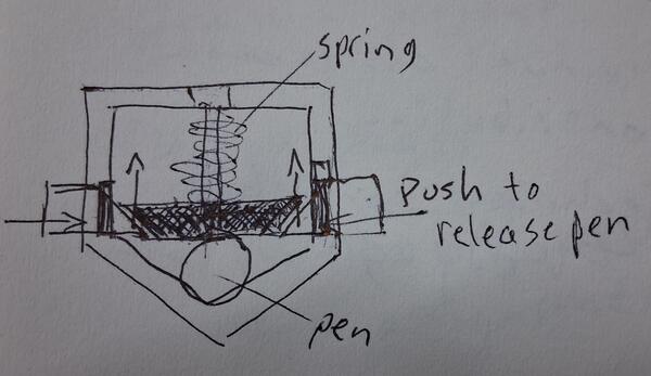
The problem is that changing the pen is difficult with just a screw holding it in it's place.
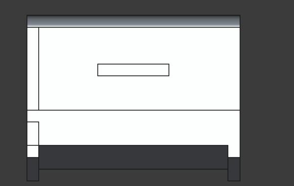
My sketch for a solution:
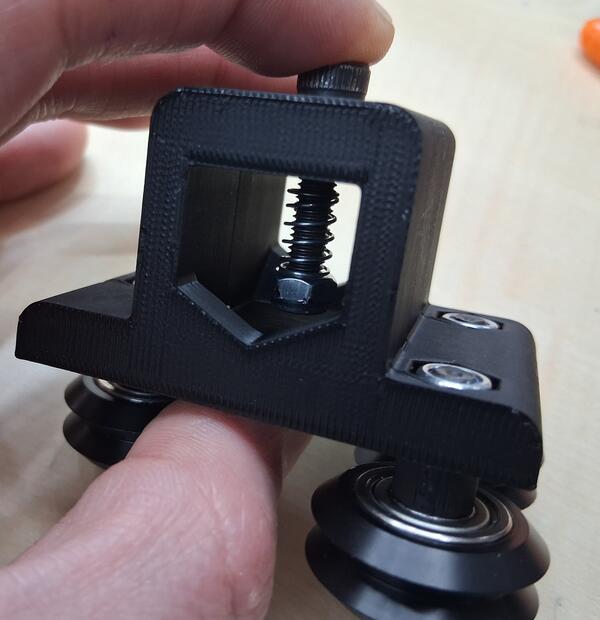
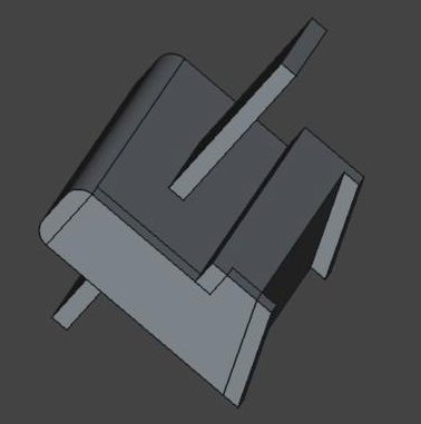
Early prototype of the idea:
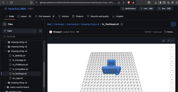
I downloaded the original tool holder's 3D-model stl-file from Hackclub's github page
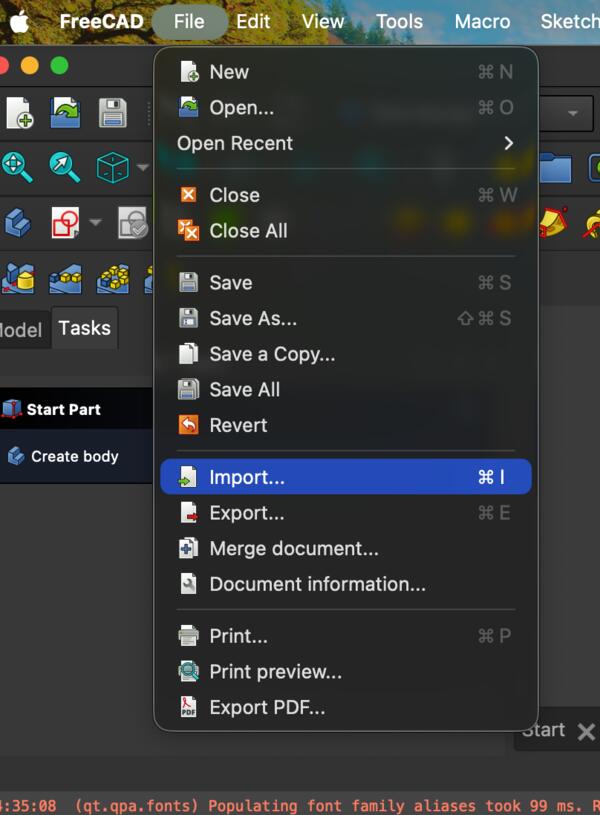
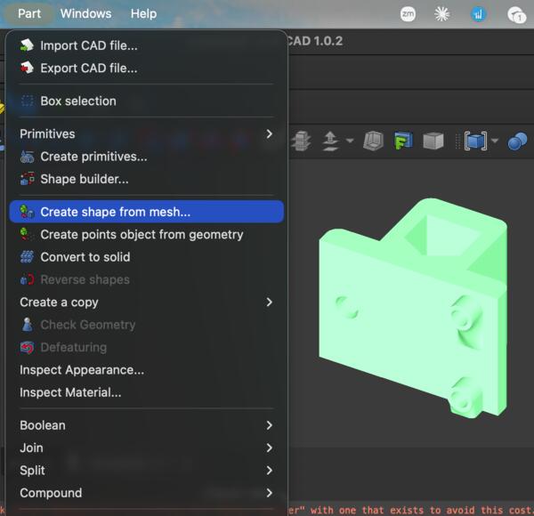
I opened FreeCad and imported the file. According to Gemini, the file is opened as a mesh which is difficult to edit, so it has to go through a few steps. I followed these steps:
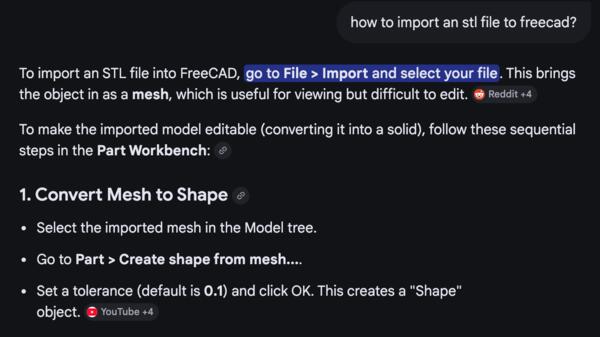
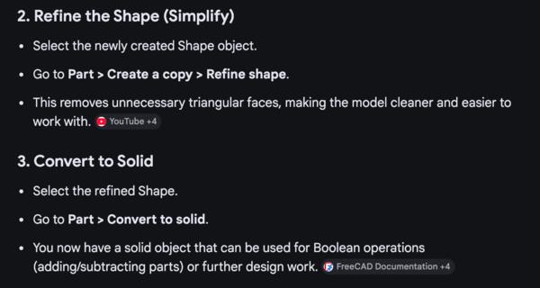
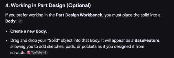
In screenshots it goes like following
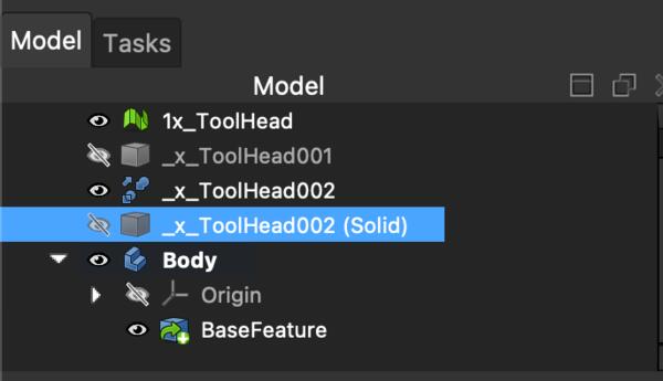
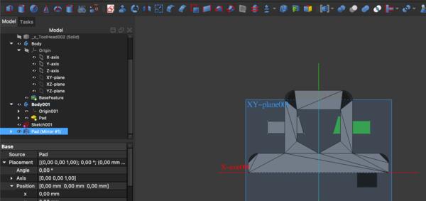
In Part workbench have the part selected:
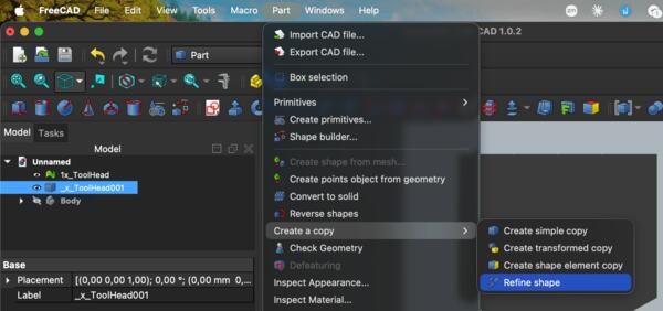
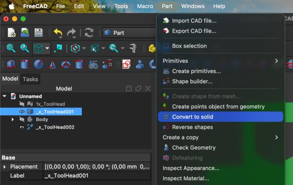
The resulting Tree view looked like this:
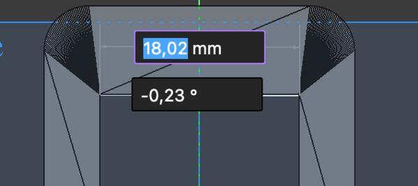
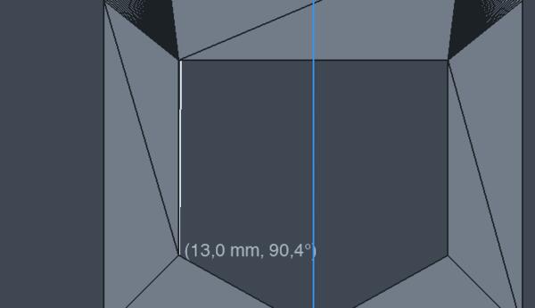
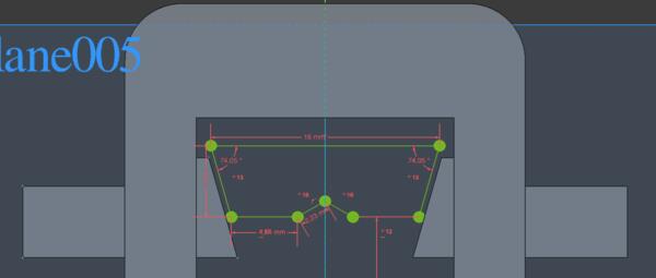
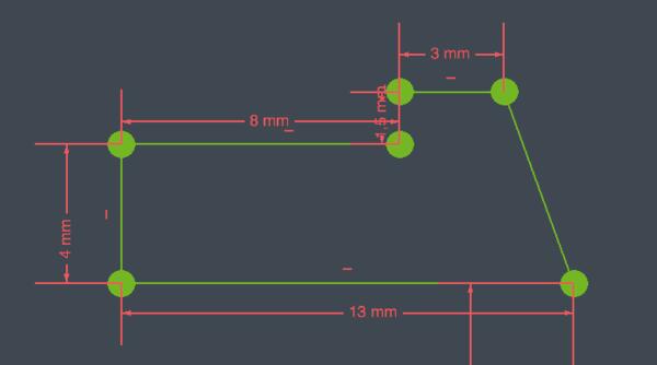
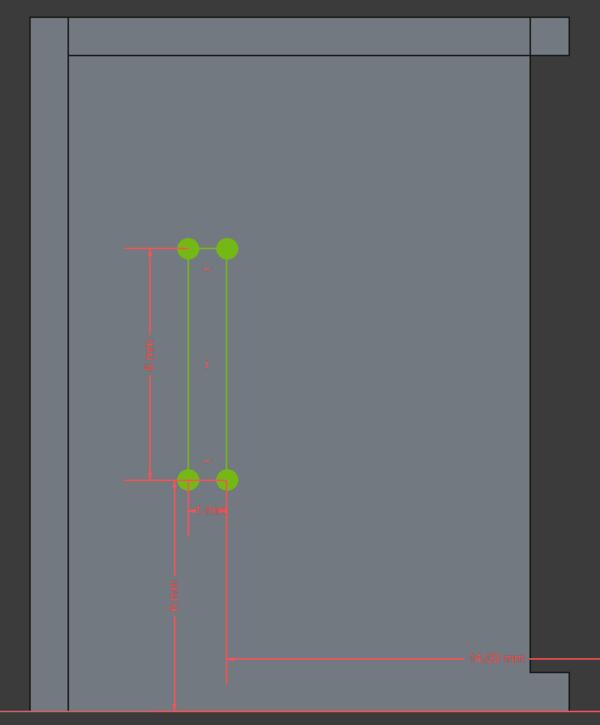
The dimensions for the hole in the holder were about 18mm wide and 13mm high.
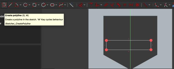
So I began modeling the first piece in Sketcher with the original holder visible.
I soon switched to polyline instead of rectangle as the idea clarified.
Then I added constraints (in short) and ended up with this sketch:
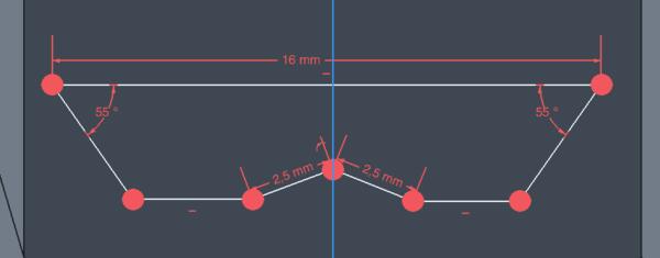
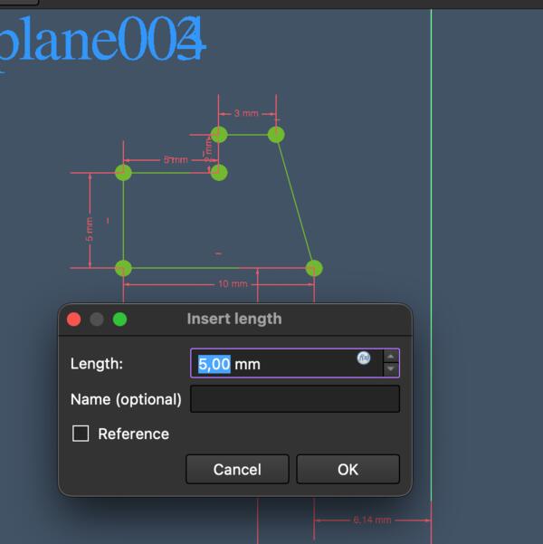
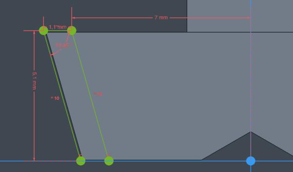
I decided to move to sketch the side buttons, which would probably inform the middle button mechanism as well. I used polyline tool and after setting constraints, the result looked like this:
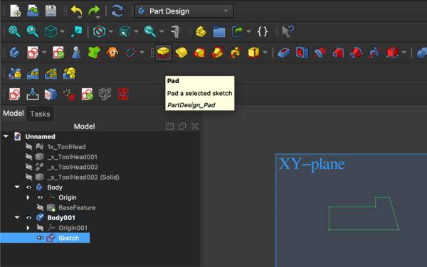
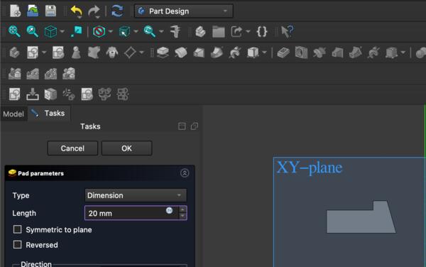
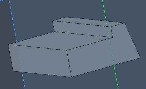
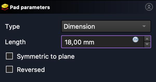
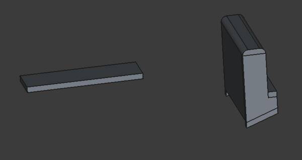
As the sketch was fully constrained, I moved to Part Design workbench and made a Pad out of the sketch.
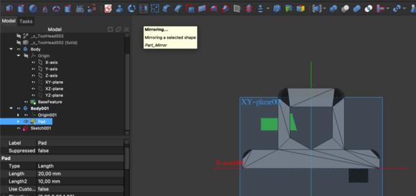
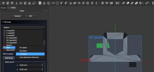
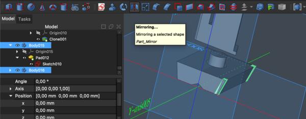
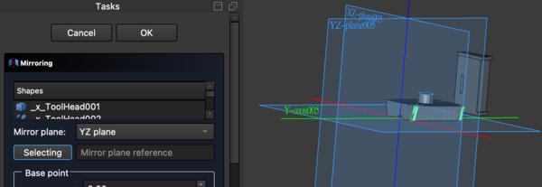
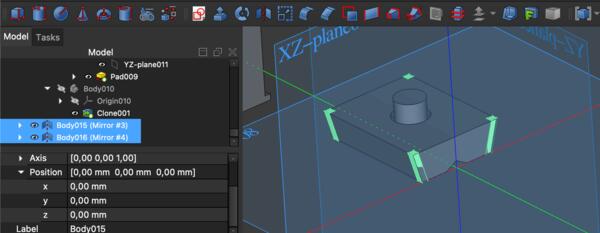
I continued to make a mirror piece for the side button. After a while of trying it out, I learned that this operation has to be done in Part workbench and use Mirroring instead of in Part Design using Mirror.
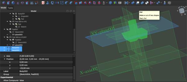
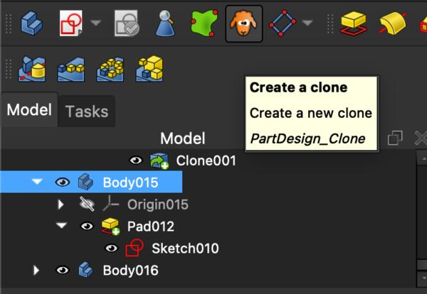
Then I moved on to make the holes for the side buttons to the original tool holder piece with boolean cut operation on Part workbench. The piece that is to be to cut needs to be selected first and the piece that "does the cutting" is selected after.
After the boolean cut, I realized that I lose the piece that was used for cutting so I had to reverse it and make the boolean cut with a clone of the piece.Then I repeated it on the other side as well.
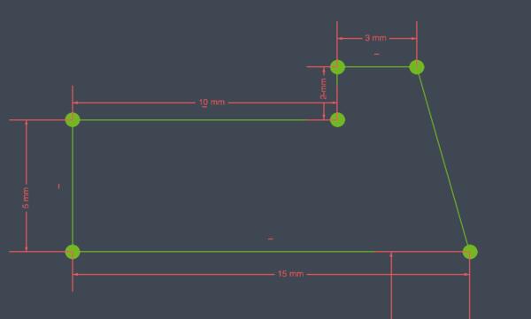
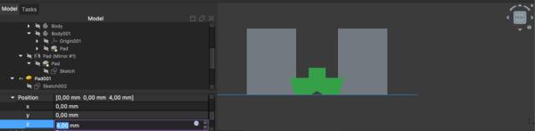
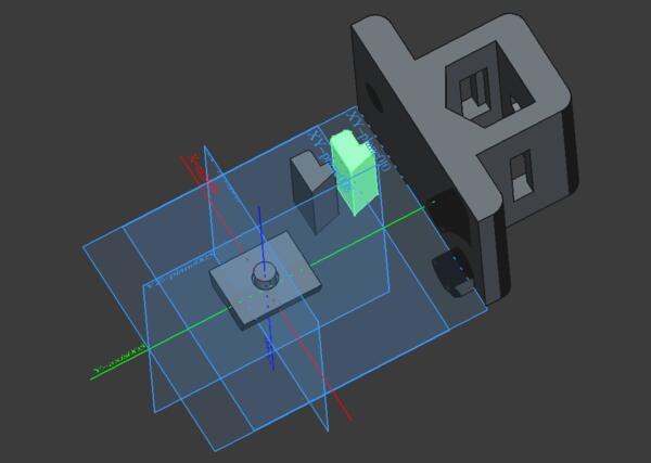
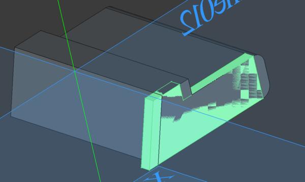
Then I finished the button middle mechanism, particularly its dimensions, constrained it as shown below, and made a pad out of it.
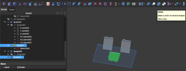
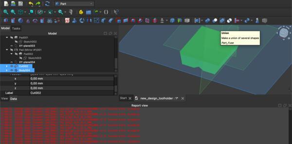
Now I wanted to make a place for the string to attach nicely, and for that purpose I made a cylinder to be set with boolean union to the piece. This turned out to be much more difficult than expected: I spent a lot of time with trying to make this work and couldn't figure out what was the problem.
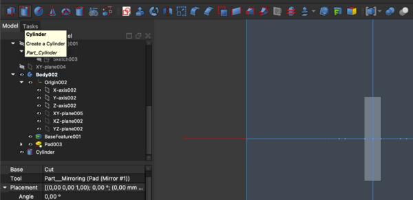
Another problem was to make the piece on the same plane as the other pieces, which didn't go as easily.
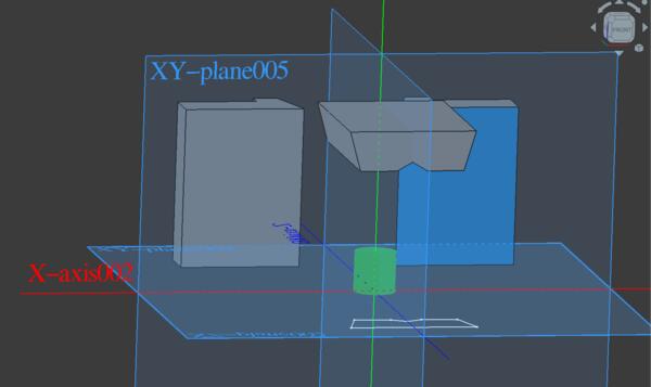
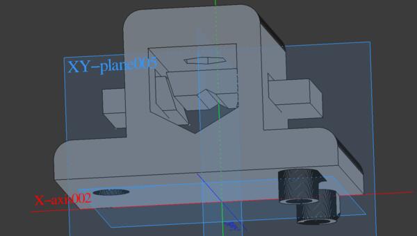
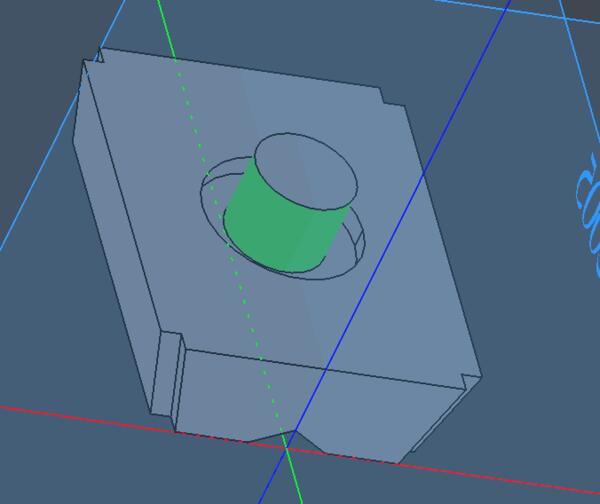
Only after getting back to it after weekend, I realized that I need to make the cylinder with a sketcher first and then it was quite straight forward. So I made a circle with Sketcher, made a Pad out of it, and placed it on top of the middle piece. I also developed the idea a bit and made larger cylinder (6mm radius) that I used to make a hole with boolean cut. Inside the hole a made another cylinder with 5mm radius and used boolean union.
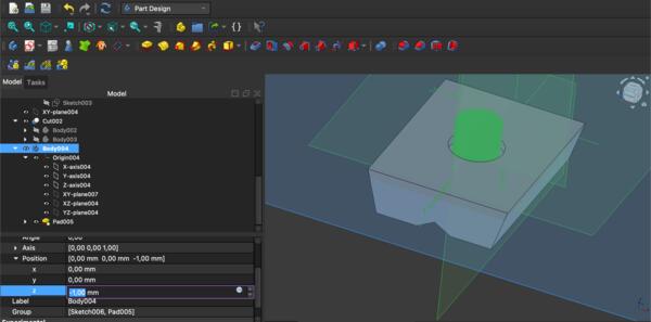
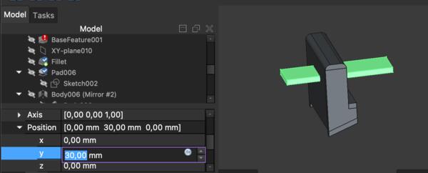
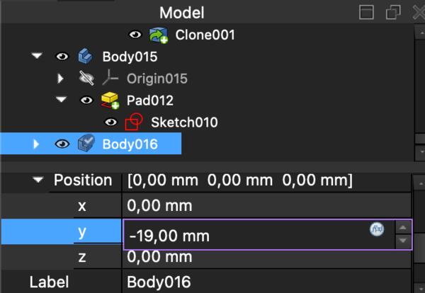
Then I also moved the middle piece downwards and didn't care that there seemed to be two sets of axises between different pieces as long as they appeared to be at the same level.
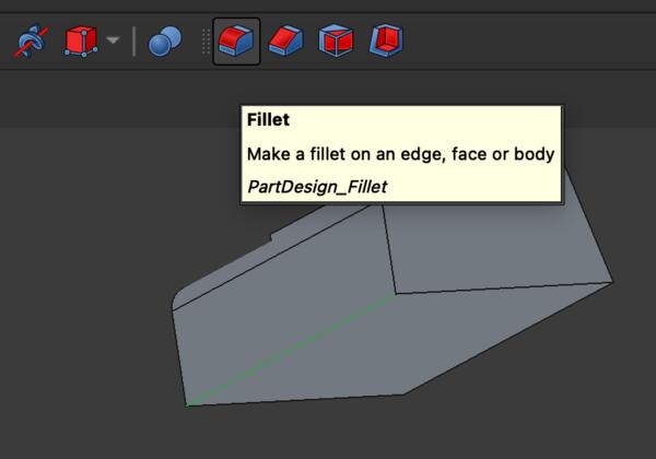
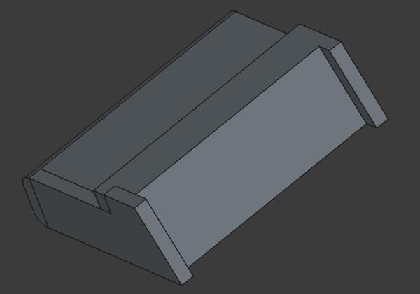
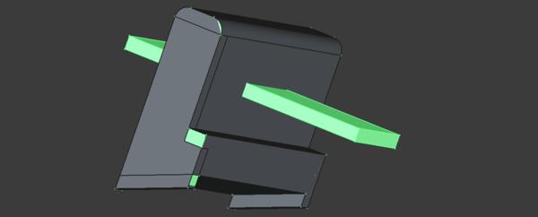
I also shortened the button pieces slightly and added fillets to the so they feels nicer to fingers.
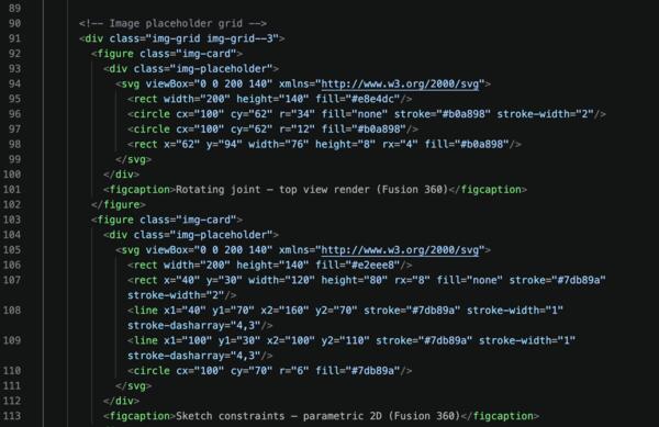
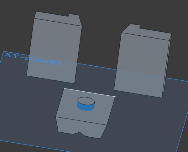
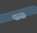
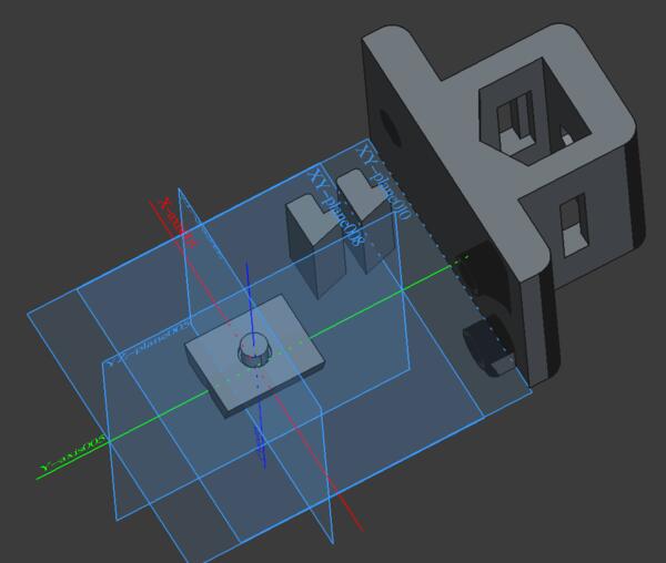
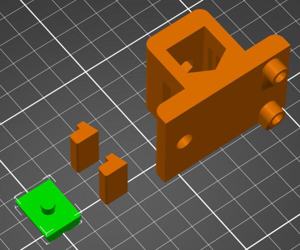
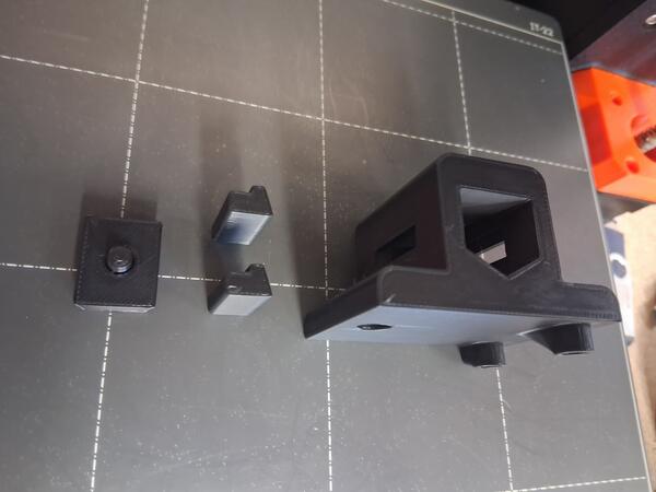
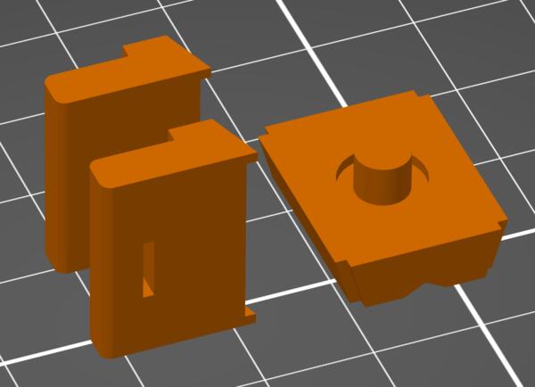
Here are all the pieces ready to be printed.
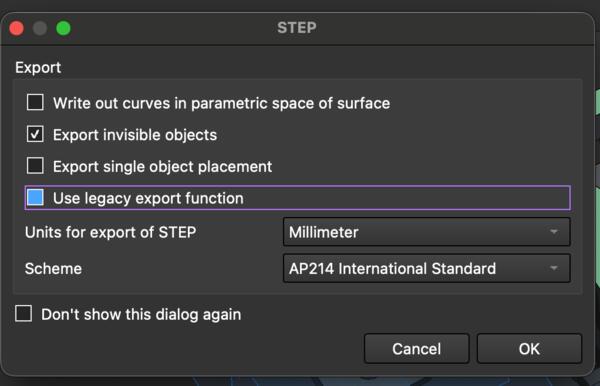
By selecting one piece at a time, I exported the pieces one by one as STEP-files.
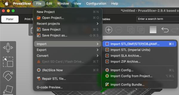
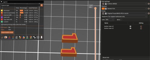
Then on PrucaSlicer I imported all of them one by one.
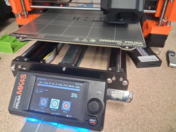
Then started the printer.
It appeared that the buttons are too large for the holes as they were exact boolean cuts and the filament is soft enough to make the hole a bit smaller as it solidifies around the hole. I tried rasping the button piece but soon decided that it’s but faster and simpler to update the model and print new buttons. Thus, I made new buttons which were 2mm narrower. FreeCad was co-operative enough to do that quickly and the printing took less than 5min.
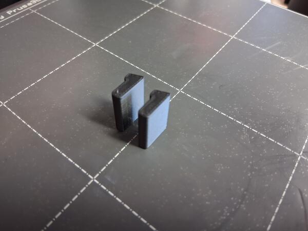
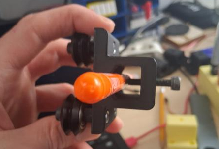
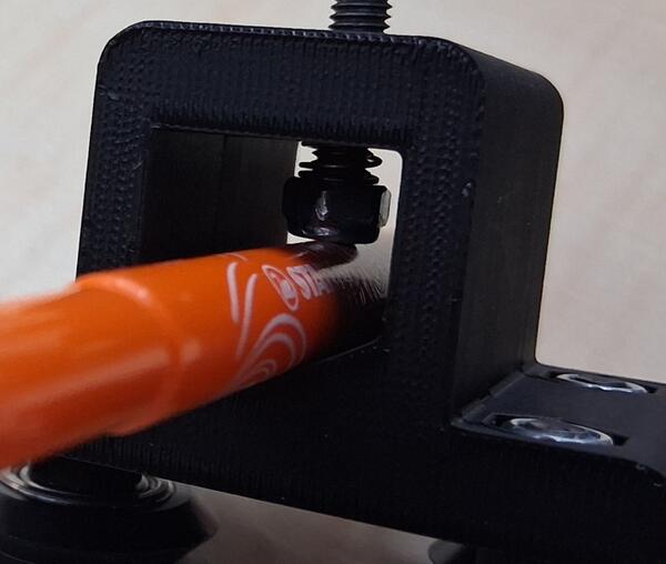
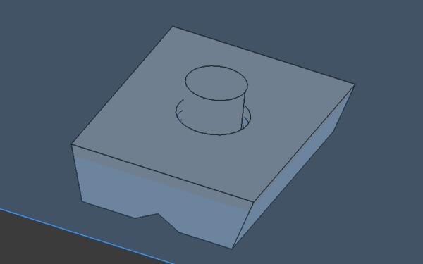
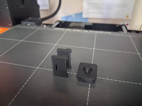
Now the mechanism works as planned.
The assembly is a bit tricky but doable, and the whole thing is somewhat wobbly and the pieces drop out easily.
There should be further mechanism to keep them in place or the pieces should be larger. However, the hole for the pen is quite small and making larger pieces might interfere with the pen. My improvement idea was to add rails for the middle piece on the buttons. I used the same sketch as for the buttons but made it a 1mm thick pad and moved it 1mm on X-axis. Then used boolean union (two times) to make the following.
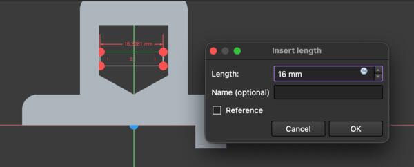
I also wanted to make a hole on the button to aid in assmebly. So I made a pad to be cut a hole in the button.
This happened to be much more difficult than expected because FreeCad didn’t make a cut but left the expected hole filled with the cutting pad.
Couldn't figure it out so I went back to the button piece before making the rails, made the cutting pad again, and now I was able to do the boolean cut. Then I did Cmd + Z to document it and with Cmd + Shift +Z the FreeCad crashed, which it does too often. It recovered only on the part which had rails in it and now removing them wasn’t possible anymore. It also had the cutting pad sticking out of it, fused in, not allowing to remove it either. I guess I just leave this and go get some lunch. Stupid FreeCad.
After lunch I was able to remove the cutting pad. I did again the hole with a new pad and the original button, and then made new rails which were then unioned to the button with hole.
I moved on to the middle piece and making the rails on it as well I started with sketching a piece that is the same size as the corner of the middle piece.
After making a 1mm pad of it, I cloned it and placed the clone to another corner
Then I mirrored these two pieces to make similar pieces to the two remaining corners.

Then I did boolean cut for each of the corners. I also made a wider hole for the spring by sketching two circles, 8mm radius and 6mm radius, making them pads (cylinders) and cutting and unioning them with the middle piece. Then it looked like this.
Then I exported the two pieces and imported them to PrusaSlicer to be printed.
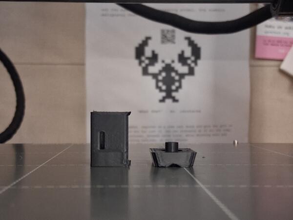
Even the 1mm overhang gets a bit damaged by gravity.
Turns out this improvement wasn't much of an improvement. 1mm rails did not make the mechanism any more robust and the pieces were falling apart almost as easily. Again I learn that 1mm with 3D print is next to nothing. Also the mechanism wasn't as smooth as before.
I used the holes to keep the buttons in place during assembly as shown below, but with the pieces of wires as aid, the holes were quite useless.