Week 3: Computer Controlled Cutting
The main outcome for the week
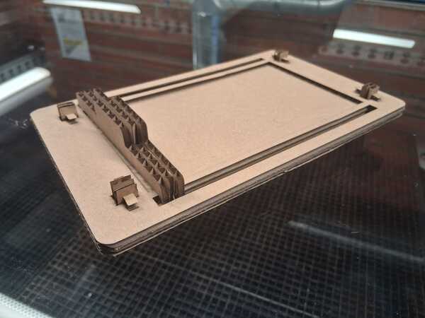
I designed and cut a prototype of a notetaking pad:
Design files made in these week are available at my gitlab repository
Vinyl Cutting
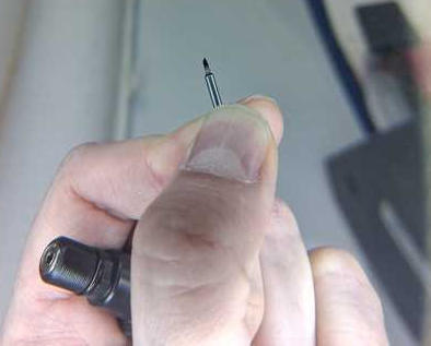
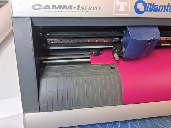
We began the introduction to vinyl cutter by inspecting the knife: in the image you can see the offset. We put the knife back and turned the holder just enough to see the tip of the knife.
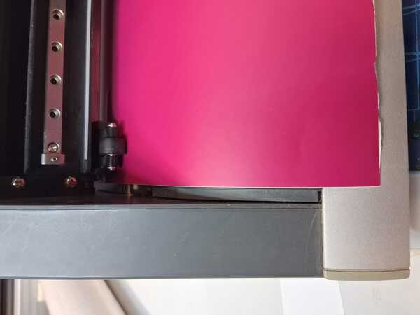
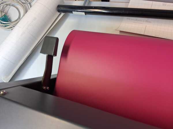
To set the vinyl ready for cutting, it should be set parallel to the side line, on top of the teeth (white lines above the vinyl show their location) and under the wheels. Then the clamp on the second image presses the vinyl in it's place. In the third picture below, there's also the proximity sensor visible next to the corner of the vinyl. The fourth picture demonstrates a good line to easily cut the vinyl.
The cutter wasn't unloaded by the previour user, so Kris did it by pressing Menu and Enter for unsetup. To begin cutting, an origin point has to be calibrated for the machine (0x,0y for the machine is bottom left corner as for software it generally is top left corner). This was done bu moving the knife on the right location with the arrow-keys and then long pressing Origin. Then we did a test cut by pressing the Test-button: the knife should cut only the vinyl but not the underlying paper. In this case it was just right.
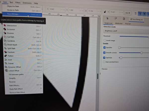
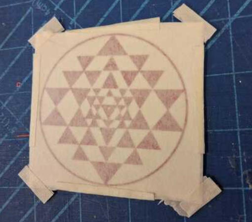
Then Kris demonstrated me how to make a sticker, but here I document the making of the sticker that I made on my own. I had a raster image of my favorite symbol that I wanted to try if it can be made into a sticker. First I had to convert it to a vector image: clicked Path -> Trace Bitmap. The image demostrates the raster image: the line is not clear enough to be cut exactly.
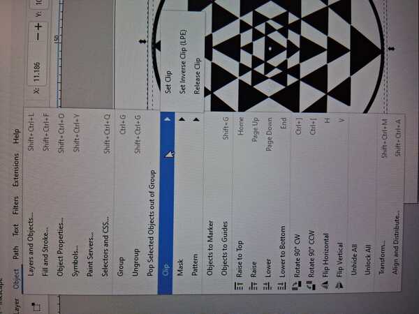
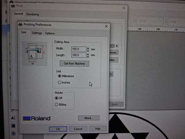
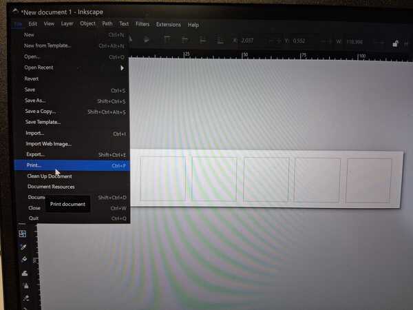
Then I removed the raster image and had only the vectorized image left. The canvas size was set so that there's no extra space around the image to minimize the extra area for cutting. This was done by clicking Object -> Clip -> Set Clip. Then I hit print, in the printing menu I confirmed the dimensions and set Rotate Off.
I set again the origin (by using arrows to move the knife and long pressing Origin) to the left side of the vinyl, on top the cut from the earlier demonstration. Then I clicked Ok in the print menu in Inkscape. The cutter did it's thing and next I was carefully weeding the creation from extra cuts.
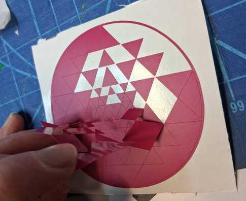
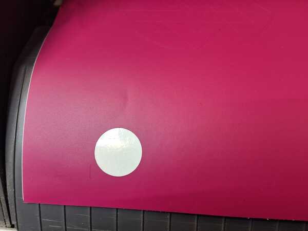
I view this following image again, because it demonstrates a mistake that I had made. I should have set the origin as near the botton side of the vinyl as possible instead of to the left side. Now my cut had made a large piece of vinyl to be cut off from the larger piece because it wasn't anymore possible to clamp it properly for next cutting.
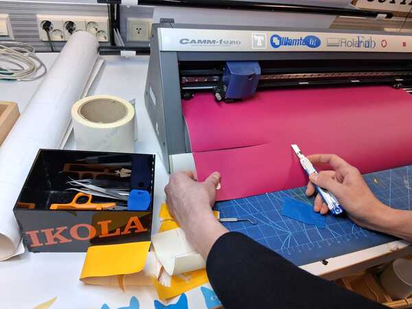
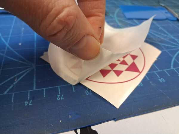
After weeding, I took a piece of transfer tape, which is slightly stickier for the vinyl than the silicon under the vinyl is for the self-adhesive glue, and the vinyl sticks to the transfer tape. Then a preferred surface for the sticker is even more sticky to the self-adhesive glue under the vinyl than the transfer tape on top of it, and it sticks to the surface as the transfer tape is removed.
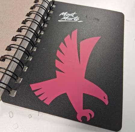
This particular sticker I wanted to give as a gift so I packaged it with the transfer tape on it, but there's also an image of the sticker we made during the demostration (my spirit animal), which I put on my notebook cover where it stays nicely.
Laser Cutting
I will begin with SAFETY concerns which need to be kept in mind when using laser cutter.
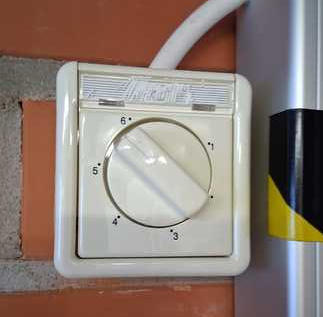
Ventilation
When entering the room before cutting, the ventilation need to be turned on: in our lab to six. This will remove any burning gases that gets emitted from cutting. Also, for this reason no PVC should be ever be cut with laser because it releases chlorine (and breathing it can cause severe lung damage and even death through suffocation to body fluids). If I begin to feel dizzy and/or can't feel my legs properly, I should take a break and get some fresh air to breath.
Presence
The main thing with laser cutting is to stay present when the cutting is ongoing and watch the machine trying to set on fire. There's a Pause button in case I need to leave the room for some reason. Also, if the laser gets stuck in one place, the cutting need to be aborted to prevent a hole in planet earth.
Fire safety
There can incur small flames in the cutting material, but in case of increasing/non-controlled fire in the material while cutting, I should immediately shut down the machine and cover it with a fire blanket, or in severe case use fire extinguisher (CO2 for not damaging the machine and aim it close to the fire). In extreme case I should just run away and save myself.
Cutting and tests
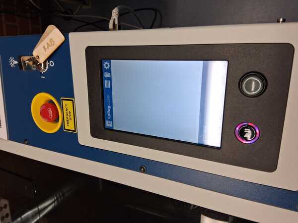
The laser cutter in our lab is Epilog Legend 36EXT. The machine starts by turning the key and then it takes a while to get initialized. While waiting we opened Inkscape on the computer connected to the cutter.
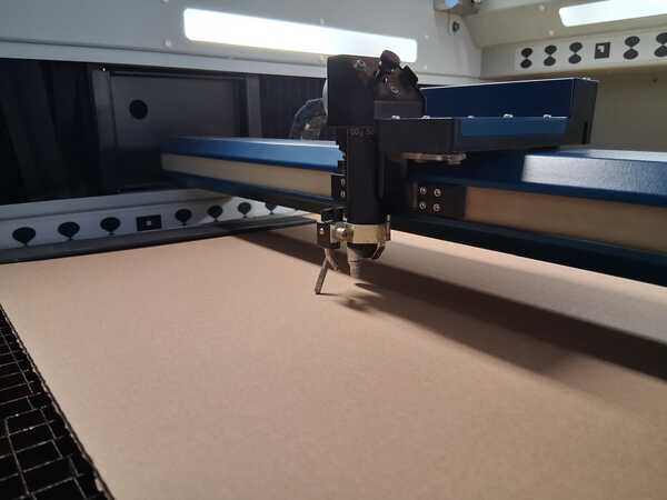
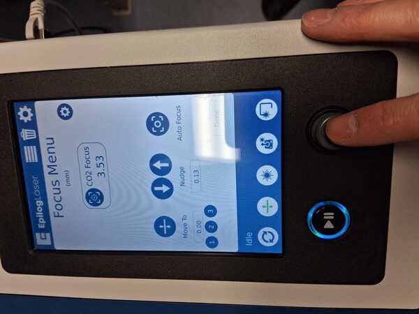
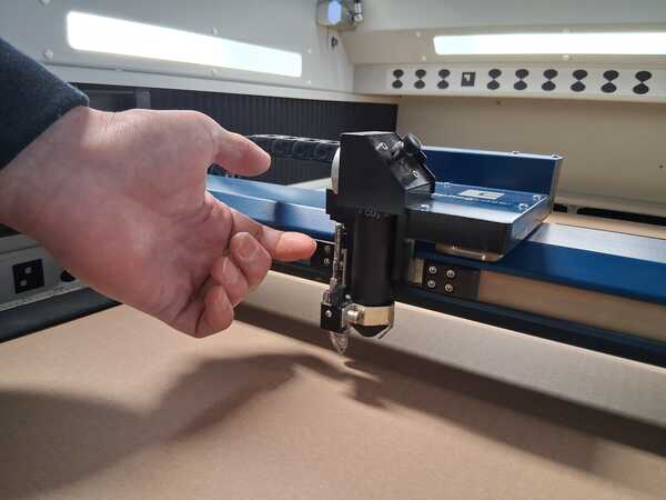
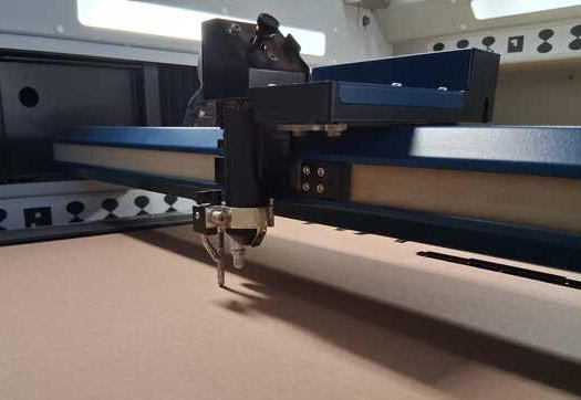
Here the material (cardboard) has been placed "belly down" (easier to clamp side than the middle) in the cuttter. Setting the distance (focusing) happens by releasing a small bar with a magnet near the lense and let it rest on the material. It's correct distance is then adjusted in Focus Menu by nudging with the joystick the material down in small increases, just enough for a normal print paper to fit between the bar and the material. Then lift the bar back to the magnet.
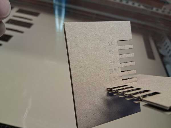
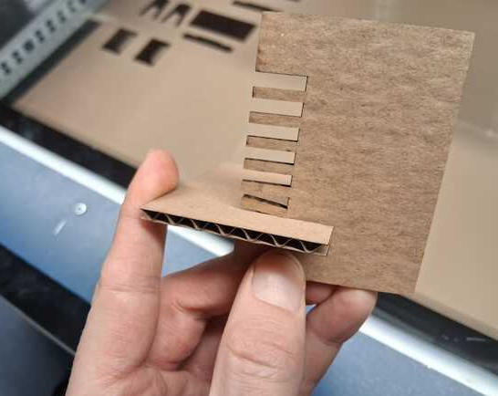
The first test cut that Kris printed looked like this: the first image shows the right fit and thus the material thickness to be used in the parameters for achieving that fit. In this case it was 3.4mm. The second image shows too tight of a fit (3.3mm)
Then we did a second cut to test right power and speed settings for the material. The model for cutting was first done on inkscape and after pressing print we position the cut area in the material, as viewed by the cameras on the lid of the cutter. On the right side image can be seen that too low power and/or too low speed the material wasn't being cut thoroughly. Usually we want to maximize speed of the cutting so this test shows (though not so clearly in the image below) that the best values are 50% speed and 50% power for this material.
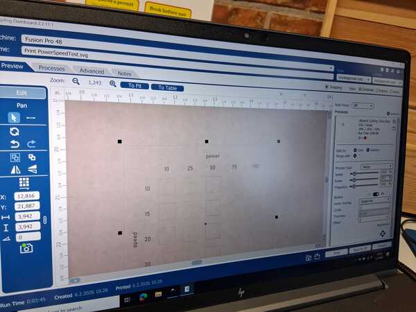
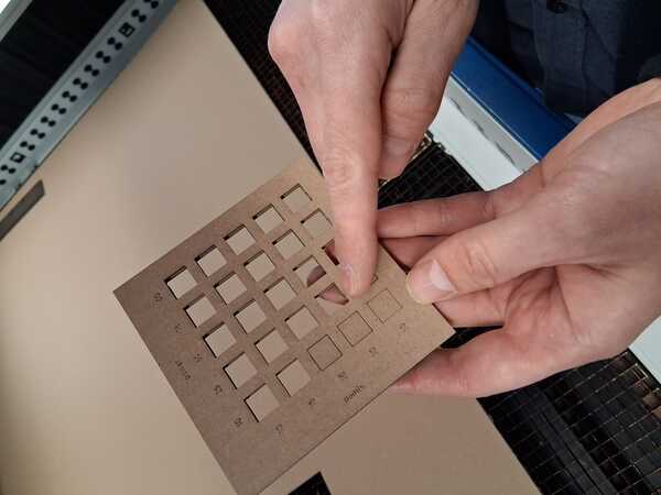
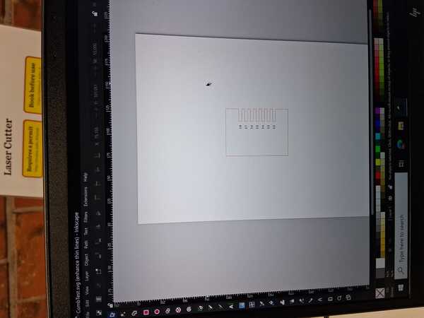
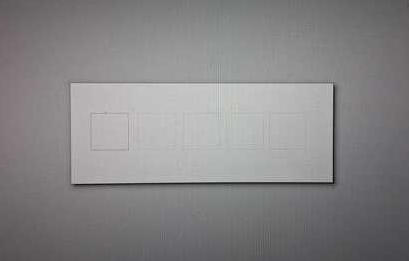
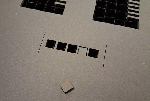
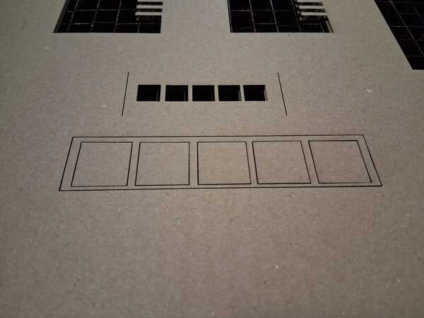
The third test, the kerf test, I did by myself. The point here is to print five equal width rectangles, and measure the difference between the expected width (5*20mm = 100mm) the real width of the five rectangles. First I did too small (10mm) rectangles which dropped through the cutter mesh. Later I heard a tip that you could leave a small area without a stroke in the design which then won't get cut but can be cut out manually after the laser cutting.
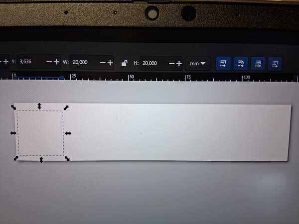
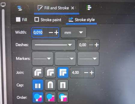
Here's a quick review how I did it on Inkscape: 1. created rectangle of correct size and copy pasted five of them, 2. set stroke width to 0.01mm, 3. distributed and adjusted them evenly, 4. resized the canvas size to contain only the rectangles, 5. and then hit Print.
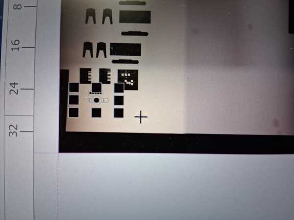
Clicking print led to Epilog software where I 1. spread the available area (non-available in pink color)
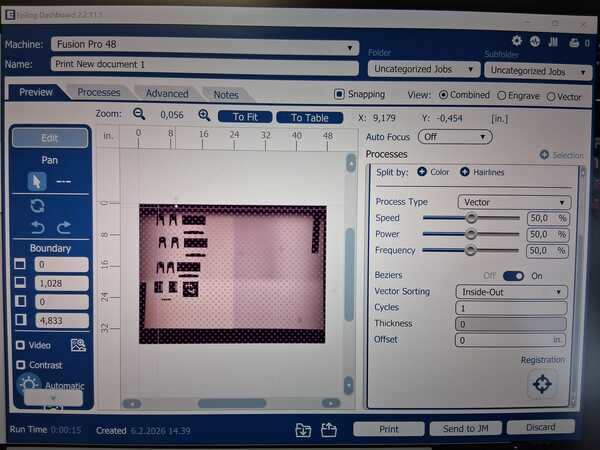
2. Positioned the print where I wanted it
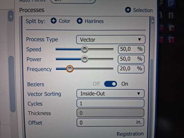
3. Set the values as informed by the earlier power and speed test
4. Sent it to the cutter and pressed the Play button.
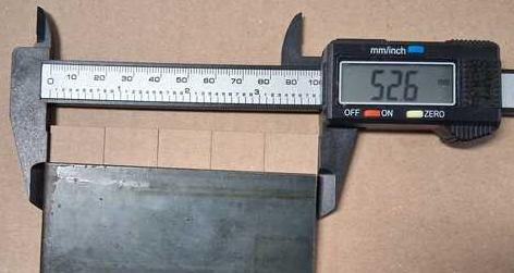
Then I let the cutter do it's thing, removed the rectangles, and measured them (with a metal piece to keep them in place and not overlapped). For the first time I used digital caliper, and was confused of the first measurement: 52.6. Quite soon I realized that it has to be calibrated to zero, and how to do that was easy to figure out as there is a button Zero. Then I got the correct real width of 98.5. Thus the kerf is (100mm - 98.5mm) / 5 = 0.3mm.
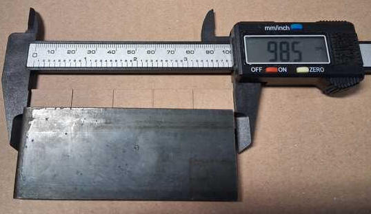
So kerf is basically the width of the laser cut on this particular material with the set power and speed (less speed/more power can widen it). The laser cuts in the middle of the stroke it's given, so half of the laser width cuts over the rectangle. This happens on both sides, thus each rectangle is one cut width narrower than the expected width, five rectangles are five cut widths narrower.
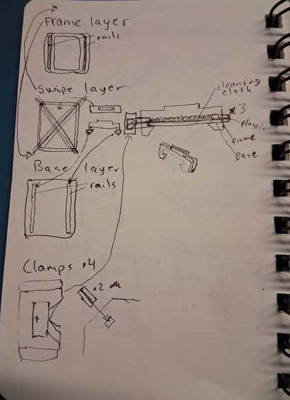
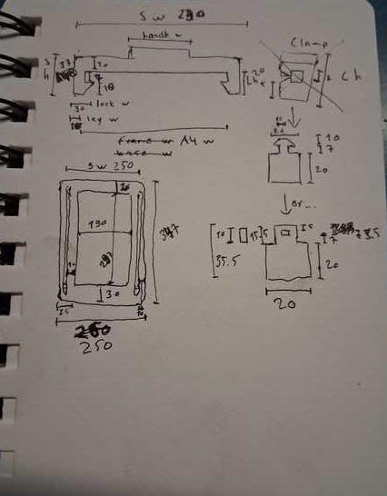
Prototype: Cardboard Tablet
I began by sketching the idea on my notebook. After the first sketch (first page/image below), I opened a spreadsheet on FreeCad to list the parameters that would be needed. The list became quickly much longer that I had expected. Thinking about the parameters in advance was also beneficial, because it required me to be more precise about my idea.
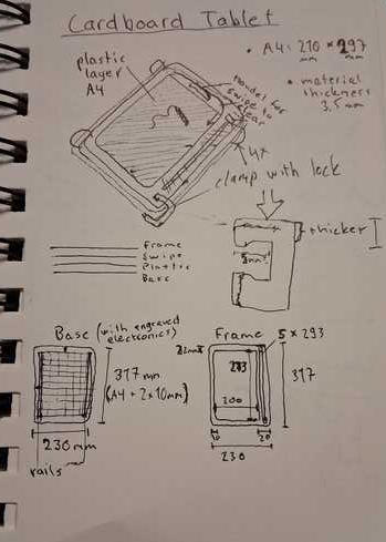
Initially I thought the tablet as the size of A4 but I decided to make the tablet half sized to save material and cutter. However, it happened to be rather difficult to change the parameters all at once in the FreeCad spreadsheets. I didn’t have any handles in the cells to expand the formulas (like the many instructions were expecting, which has happened before also in other situations). I ended up copy pasting the parameters to excel and back after dividing all the parameters by 2.
Inkscape
Soon I realized that we had done the tests on Inkscape, so I switched to that. (Slightly relieved that I didn’t have deal with FreeCad with this assignment, which was not the case in the end.) However, I finished with all the parameters on FreeCad and updated them as the model progressed. I was thinking that the kerf is working for me, for example when measuring the swipe leg width compared to the rail width: it would automatically leave a little space between them (not enough it appeared).
Here's how the model was done on Inkscape.
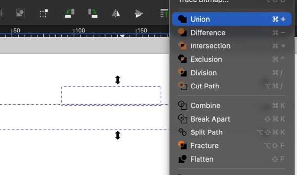
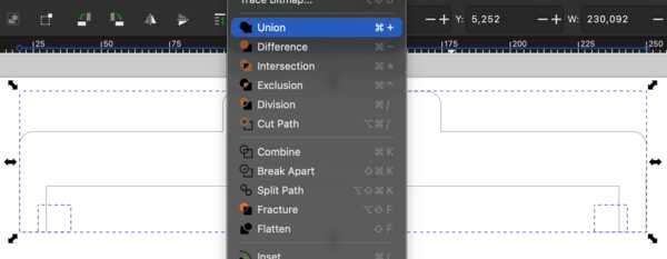
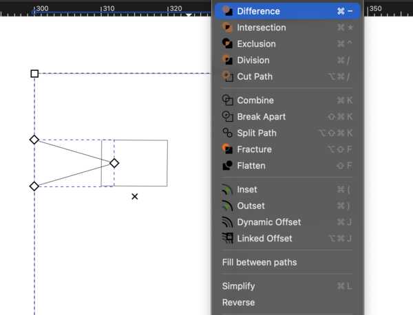
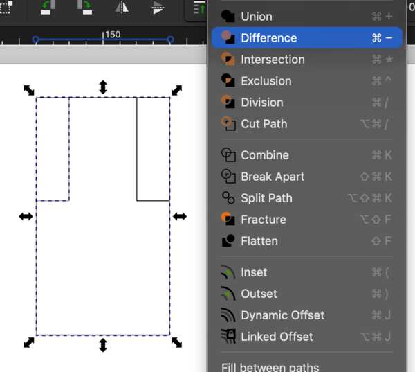
I began with the swipe and it's handle, which I did by attaching two rectangles of correct sizes: Path -> Union. The legs I did with two more Unions of rectangles of right size and one rectangle cut 45 degrees angle on it by Path -> Difference. Unlike in the pictures, the operations had to be done one rectangle at a time.


Then I created the frames using the rectangles and added radiuses.
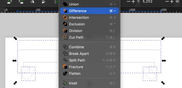
The first version fo the clamp I did with differences. However, in the end it came to look like the latter one as I thought about better ways to attach two layers (the picture from the lecture with different attachment ways helped me with this). This "clamp" was also done with rectangles and differences.
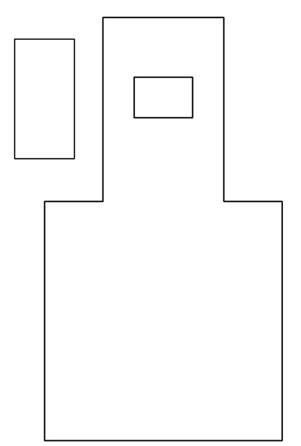
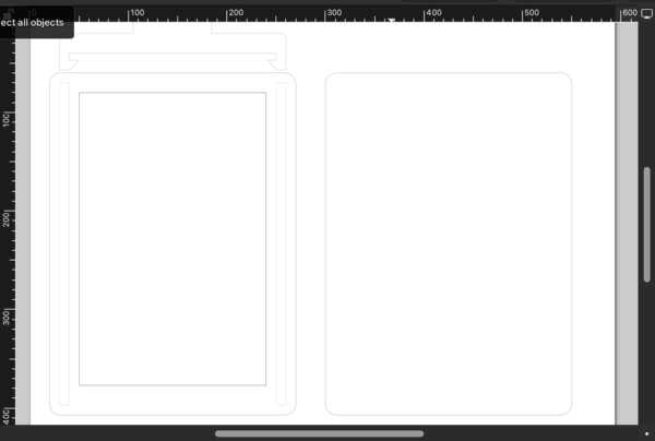
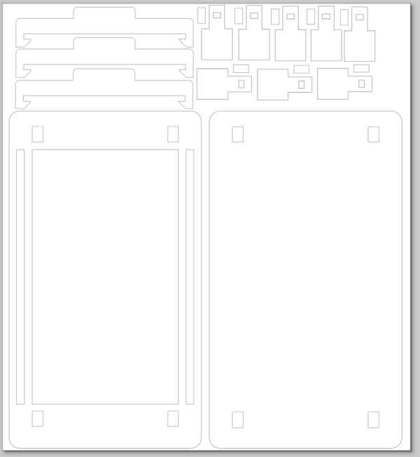
The final set for the first version looked like this:
It was only after cutting that I realized I had forgotten the rails from the base layer! This would've definitely not been an issue if I had done this with a 3D software right from the beginning.
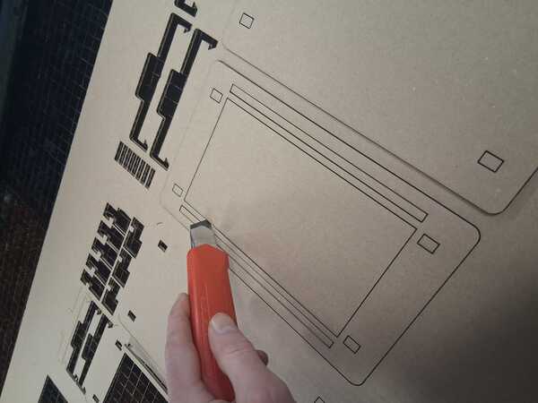
The cutting
Before starting the cutting I checked from my documentation what all had to be done and kept in mind with the laser cutter (this was Tuesday and it was written on Friday). So I put the ventilation on, turned the cutter on with the key, waited a moment, placed the cardboard in belly down with weights on the sides, and did the focusing. I also opened the computer for the cutter and downloaded my design file from OneDrive. I checked the dimensions in the parts and tweaked them as they had changed slighty, probably due to scaling the document size. Then printed.
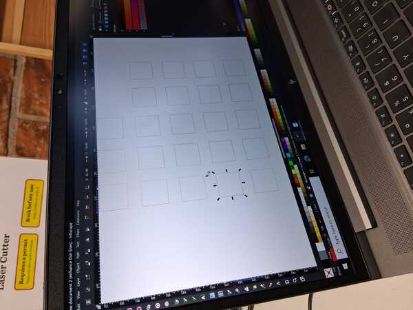
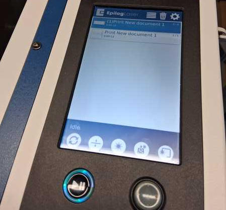
After pressing print, the design was not visible in the epilogue software. After thinking a while, I figured that what might be wrong is the file type: it was .FCStd and it should have been .svg. In the image below it is there in the top middle but nothing is selected -> not visible.
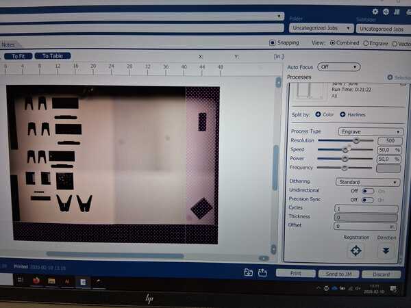
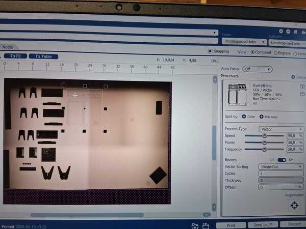
Then I re-exported the model as .svg and then printed that. It was still not visible. After a while I realized it was there but really thin. So I moved it to it’s right place on the screen (filmed by the cameras), pressed the menu button on the laser screen, chose my file and pressed play.
The laser began only engraving the area. I aborted the cutting by pressing Pause and the the Idle button. On Inkscape, I changed the stroke values to 0.01 mm and tried printing again. This was probably the reason why the design was so thin in the epilogue UI as now it was more visible. Set it again and pressed print, chose it on the cutter menu and pressed Play. Now it began cutting instead of only engraving.
But this time it did not cut everything for some reason. I checked the design and there were some parts really close to, and some over, the edge of the document. However, some lines in the middle were also being left out, so I don't know.
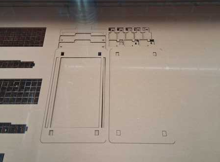
The partial cutting allowed me to test the legs and swipe, however. Legs were alright but the swipe needed more space around the rails for it to move more freely within frame and base. So I widened the rails by 1mm and lengthened the legs of the swipes by 1mm.
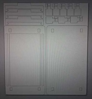
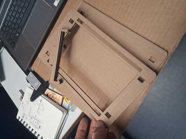
Then I printed it again, and now every line was cutted, but not fully, although the settings were the same: 50% power and 50% speed. I wondered if it was because now the cutting area was further away from the laser. I ended up using boxcutters to finish some of the cuts. Only when I assembled the pieces, I realized that the rails don't fit because there are no rails on the base layer (image on the right). That felt quite stupid.
Thus, I copy-pasted the frame layer and removed the large hole in the middle and printed a new base. This time I set power to 60%, but it appeared not to be enough to cut fully through (but better than before).
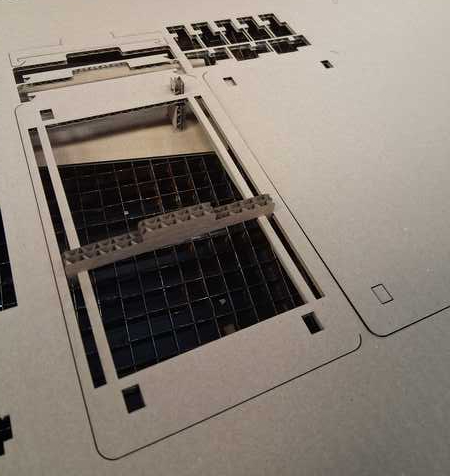
Then I assmbled the pieces together and below are a couple of images of it from top and bottom (I should have taken video to demonstrate it better, maybe later). There's not yet a plastic in between to be written on.
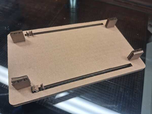
The rails were not perfect but got better when they got used to the swiping, but that would definitely require a better mechanism. Also the locks in the legs of the swipe were not working too well: they were too wide and got crushed when pushed in the rail. (I have already in mind how I could fix that.)
I finished the prototype with some paper, plastic, tape, handpaper, and paperclips. At this point the swipe had been put in place and taken out so many times that the legs/locks were broken already.