Week 2: Computer Aided Design
The main outcome for the week
I explored CAD software, mainly FreeCad, on which I made a simple model of stylus pen:
Design files made in these week are available at my gitlab repository
About documentation
Few words about documentation here in the beginning… I told Kris (our instructor) that documentation is difficult because I have to divide my attention between thinking about the rather complex stuff that I’m learning as well as think about the learning and doing itself. Mastering it is one significant learning outcomes I can expect for me if it works out. Currently I might work several hours straight and forget to eat, for example. Kris gave me some advice on that:
- think about what I do in smaller chunks
- slowing down the pace is useful
- bring focus on what I learned and explain that (possibly in one sentence)
So I’ll try to implement these ideas in this week’s learning on how to document my work.
Also, I have discussed image (and soon video) compression in the end of the documentation for the first week. I think it makes more sense to have them there with documentation for web development, so I'll keep them there for now.
Today’s topic is Computer Aided Design which is the digital side of modelling shapes, both in 2D and 3D. Which CAD program to choose depends on what you want to do, similar to oil painting vs. watercolor. Each is optimized for a specific area of tasks such as engineering, designing, animating etc. So I figured that to get started in this topic I should try out different software to personally understand their differences. So I approach this week more systematically by trying to create a same shape with each program and document the process. But as there’s only a few days, I can’t go too deep in none of them, but have the ability to discern which one(s) to focus on later in the academy.
Software I used in this week:
- Inkscape for 2D vector image
- GIMP for 2D raster image
- FreeCad for 3D model
- Blender for 3D model (Not yet quite there yet)
- Openscad for 3D model (Not yet quite there yet) (Later I want to also try out Fusion 360.)
2D
For 2D modelling Kris suggested me to work with Inkscape for vector images and GIMP for raster images as both of them are free and open source. Kris explained their difference to me so that vector images work as vertices (x,y -points) which together create lines and shapes, and each of these have specific properties such as thickness, color, etc. Raster images are based on an array of pixels which have specific values, for example RGB-values and alpha(/opacity). With these two programs I made a sketch of a new idea for final project.
Inkscape for vector graphics
I had some experience in working with Adobe Illustrator but it’s been a while since then and I’ve mostly forgotten everything. I expect Inkscape to work somewhat similarly though. I began by looking tutorials in inkscape website and began to go through the basics.
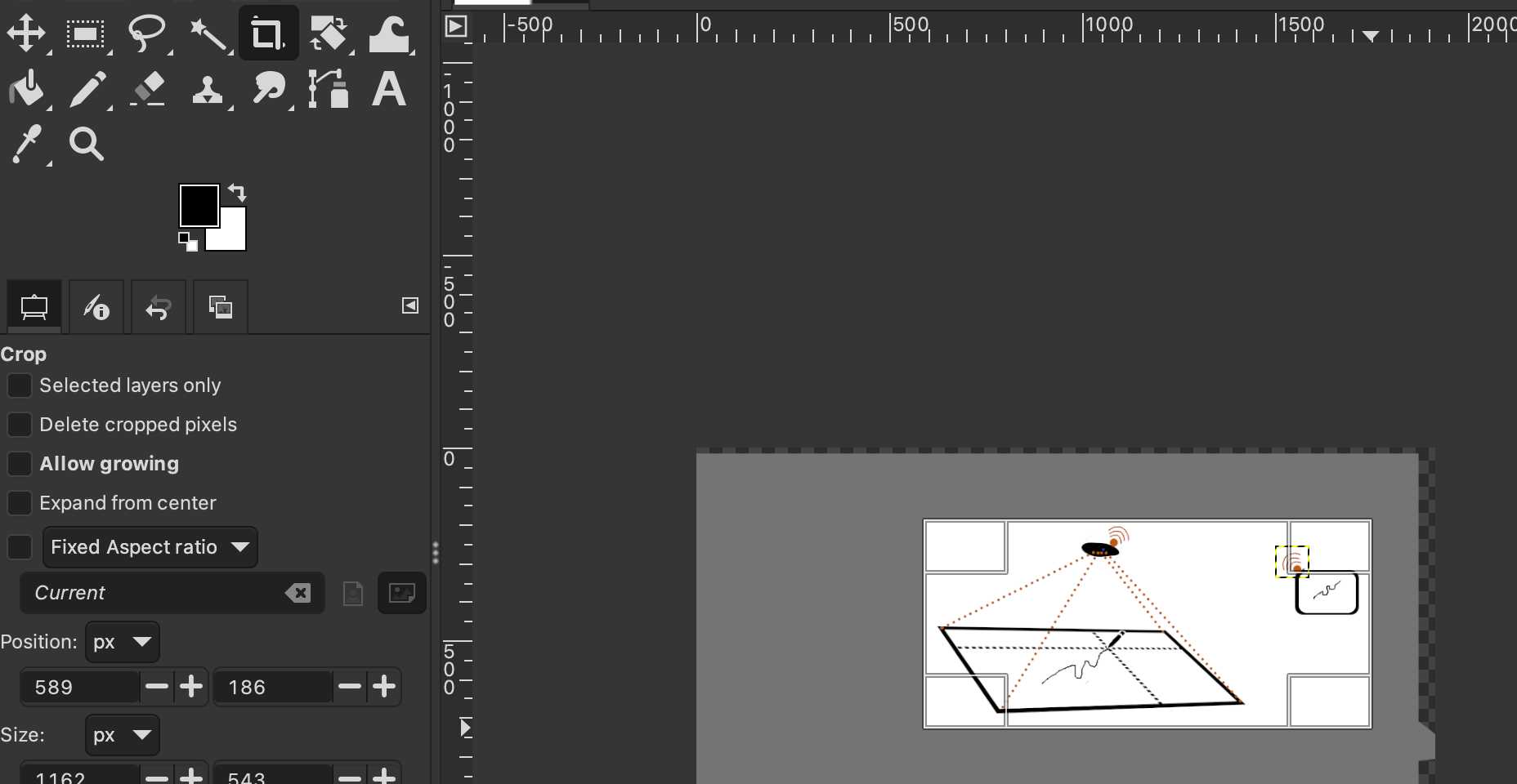
After creating a new file, I changed the orientation to landscape at File -> Document properties...
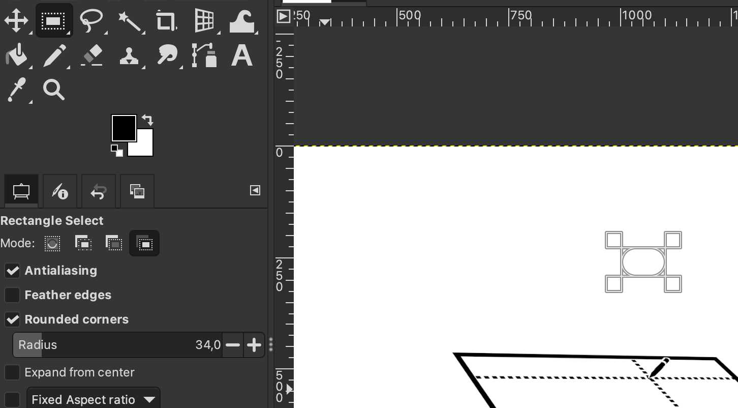
Then I created a rectangle with rectangle tool, fixed the corners with corner handle and increased the stroke width.
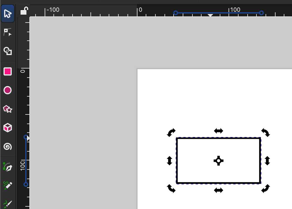
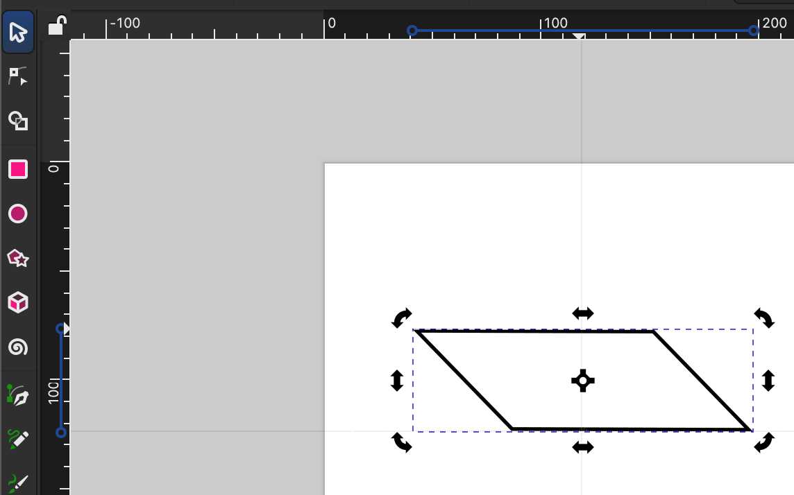
By double-clicking it with Selector tool, I was able to rotate and skew the rectangle.
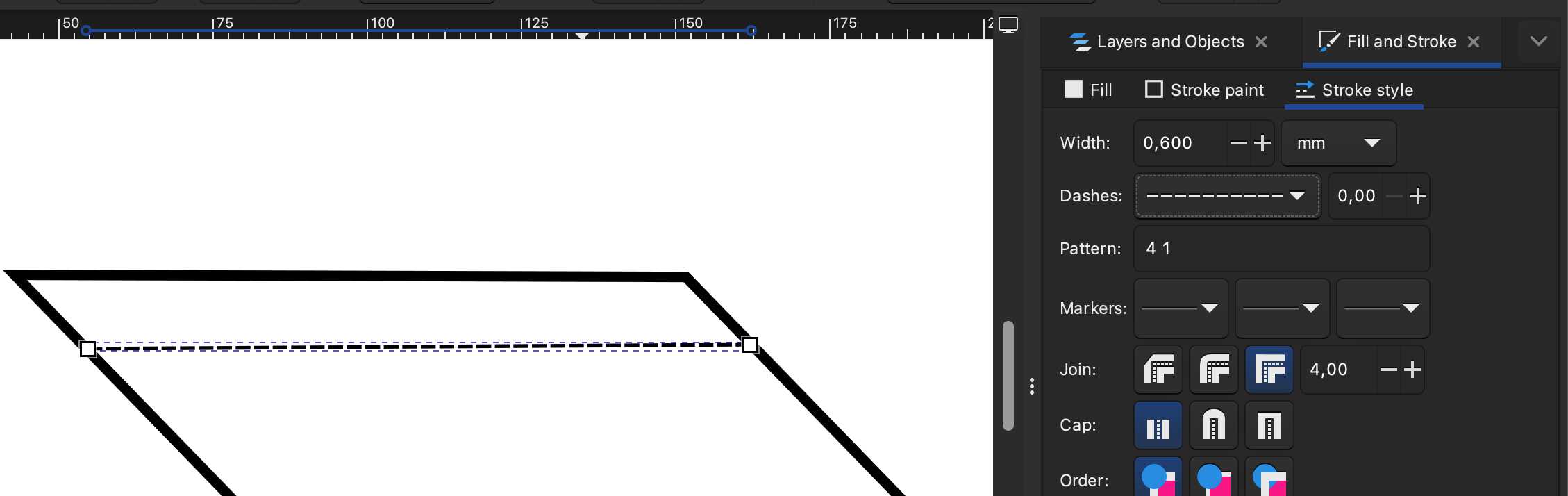
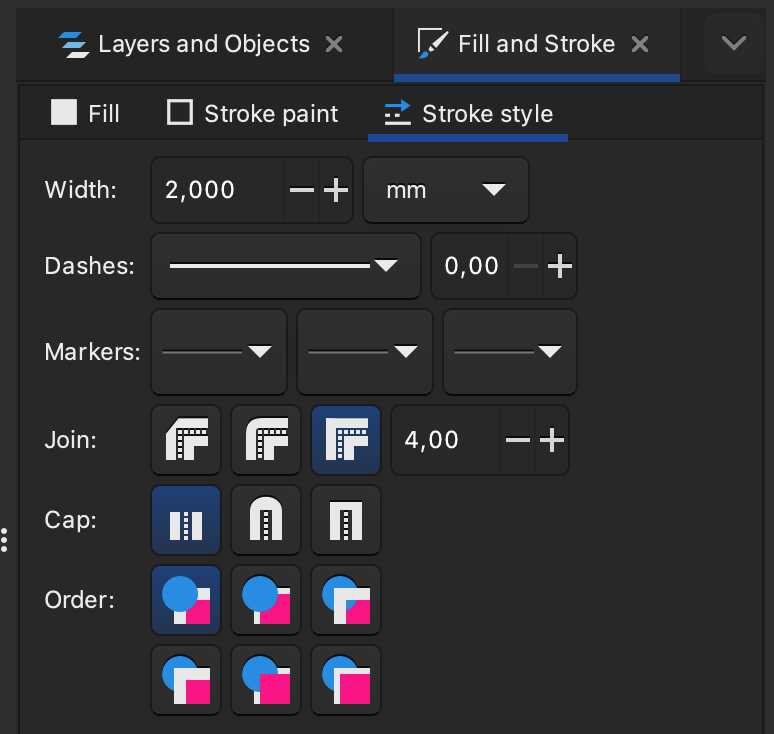
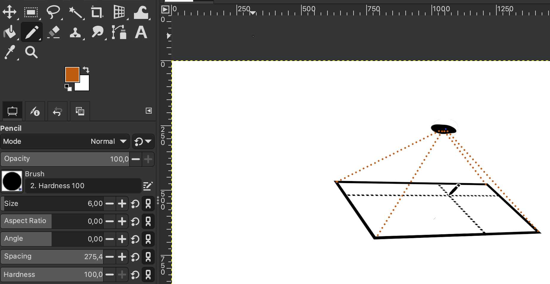
With Pencil tool I clicked mouse left button and again on the other side created a straight line and from stroke style chose dashes and fixed the width.
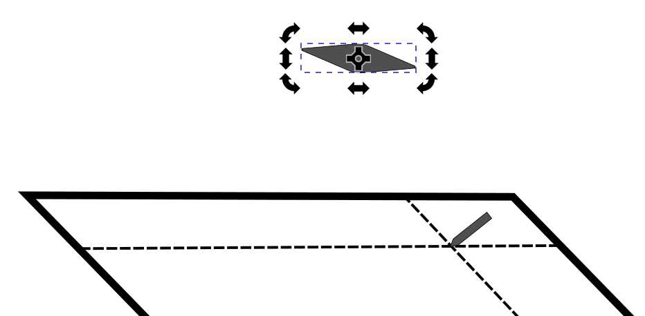
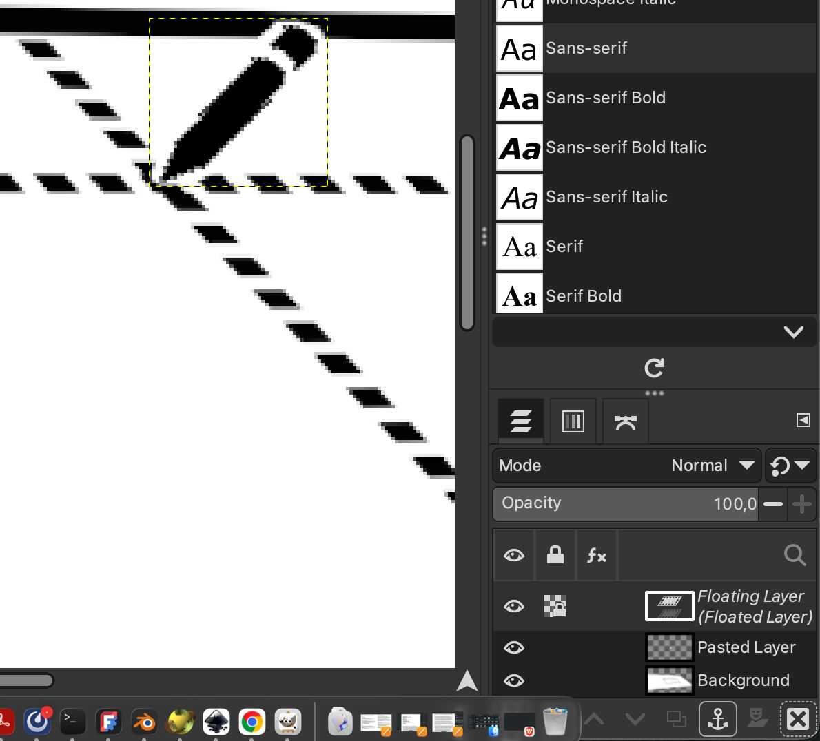
Then created a new layer on which I used pen tool to draw an image of the pen and filled it with gray.
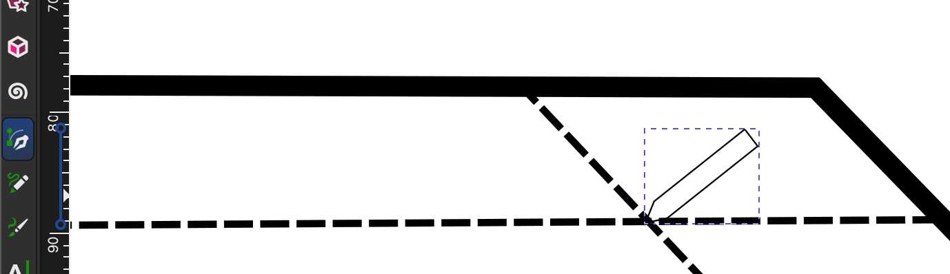
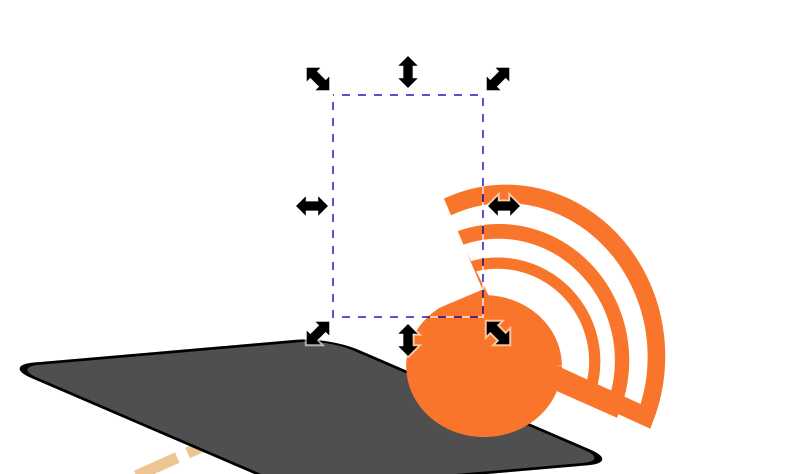
Made the “projector” using the same tools as with the first rectangle [1]. Draw the orange dotted lines (stroke paints) [2] and moved the rectangle to the top in the layer tab to make it appear on top of the lines.[3] I also draw blue line with pencil tool with no fill (not visbible in the pictures below).
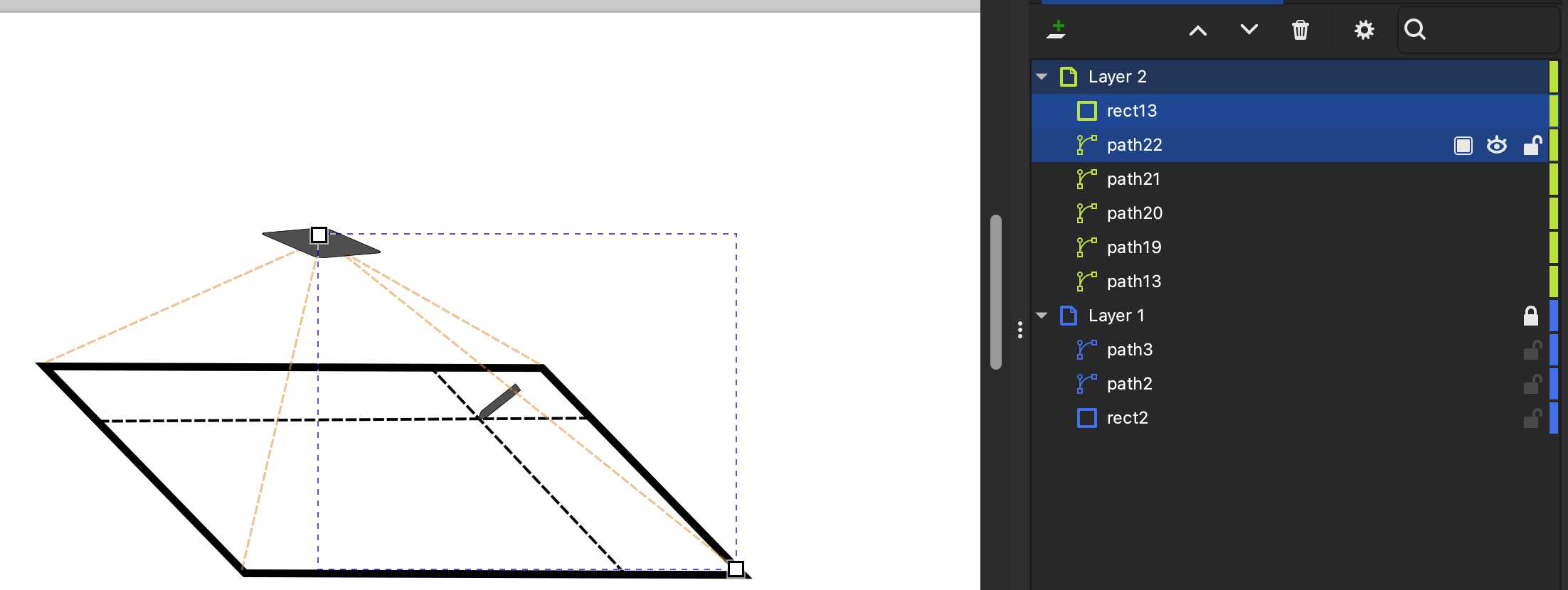
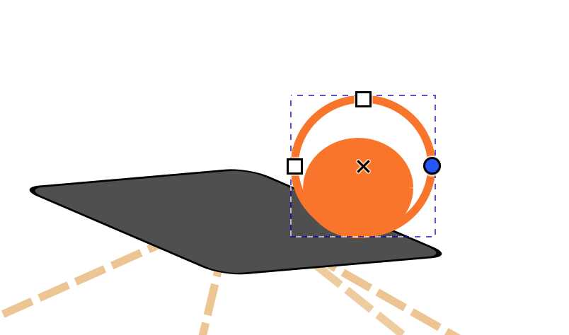
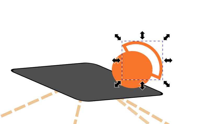
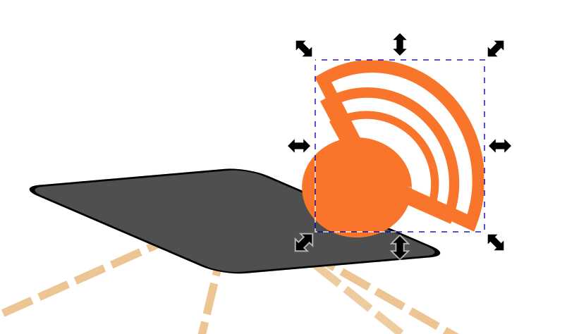
The remote connection symbol I draw with four circles, copy-pasting the first one, on top of each other and removed the fill from three largest. With the circle handles I chose the length of the stroke, and also hid some parts with white rectangles.
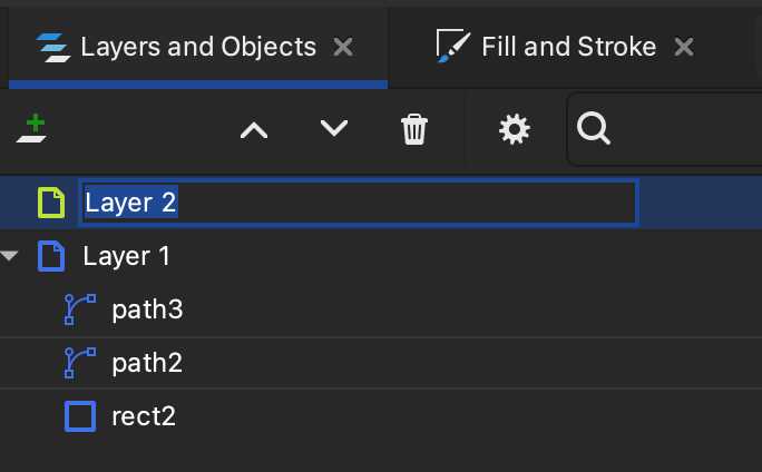
I selected all of those elements on the layer tab and copy-pasted it, and made result into a group with Cmd + G.
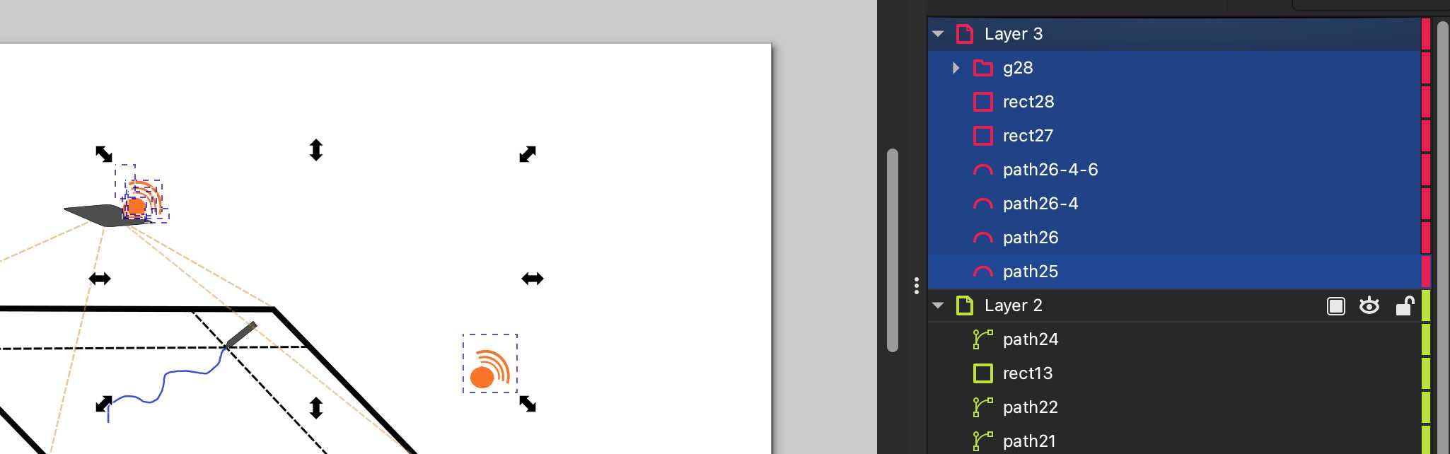
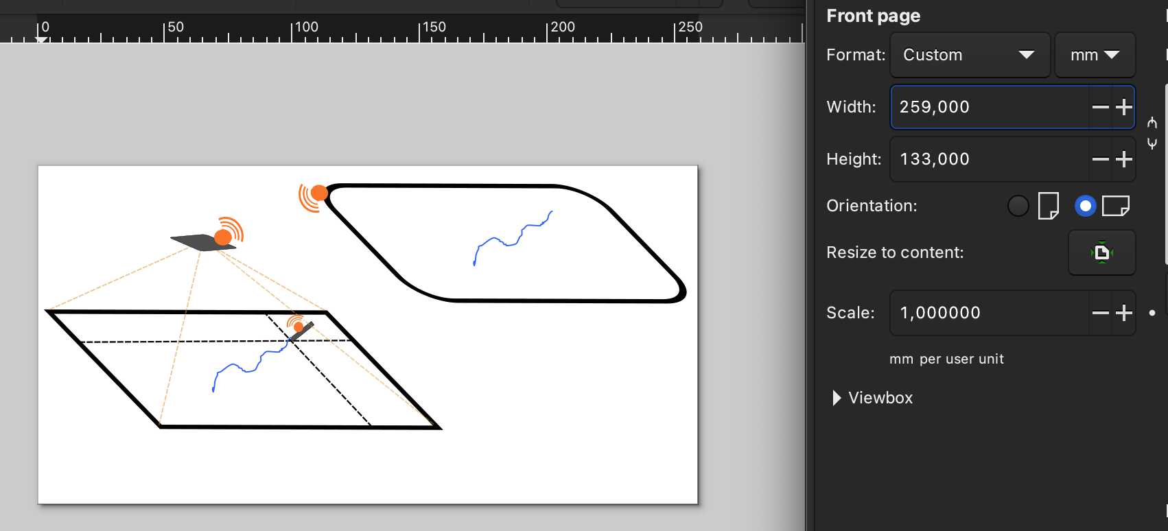
I also created a duplicate of the first layer to make a screen on which the drawing becomes visible. Deleted the elements except the screen and drawing, and moved it on the side. Copy-pasted the remote connection symbol and made one for the pen and one for the screen, and also rotated them both with clicking twice with selector tool. In the end I selected all layers and moved everything to the upper left corner and resized the canvas appropriately at File -> Document Properties…
Export as… .jpg
By doing this sketch I got quite a good feel for inkscape's basic operations.
GIMP for raster graphics
For getting introduced I went through the Gimp Tutorial.
Moving around:
- Option pressed: move
- Ctrl + Shift: scale size
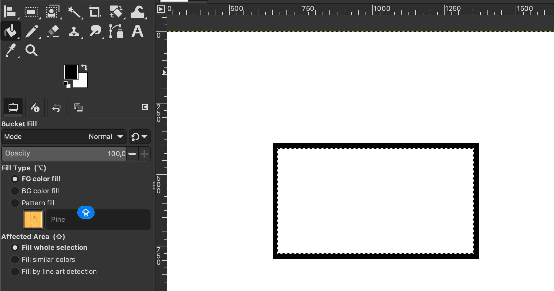
I began by creating a rectangle using "Rectangle selector" and (bucket) filled it with black. Then made another rectangle on top of it:
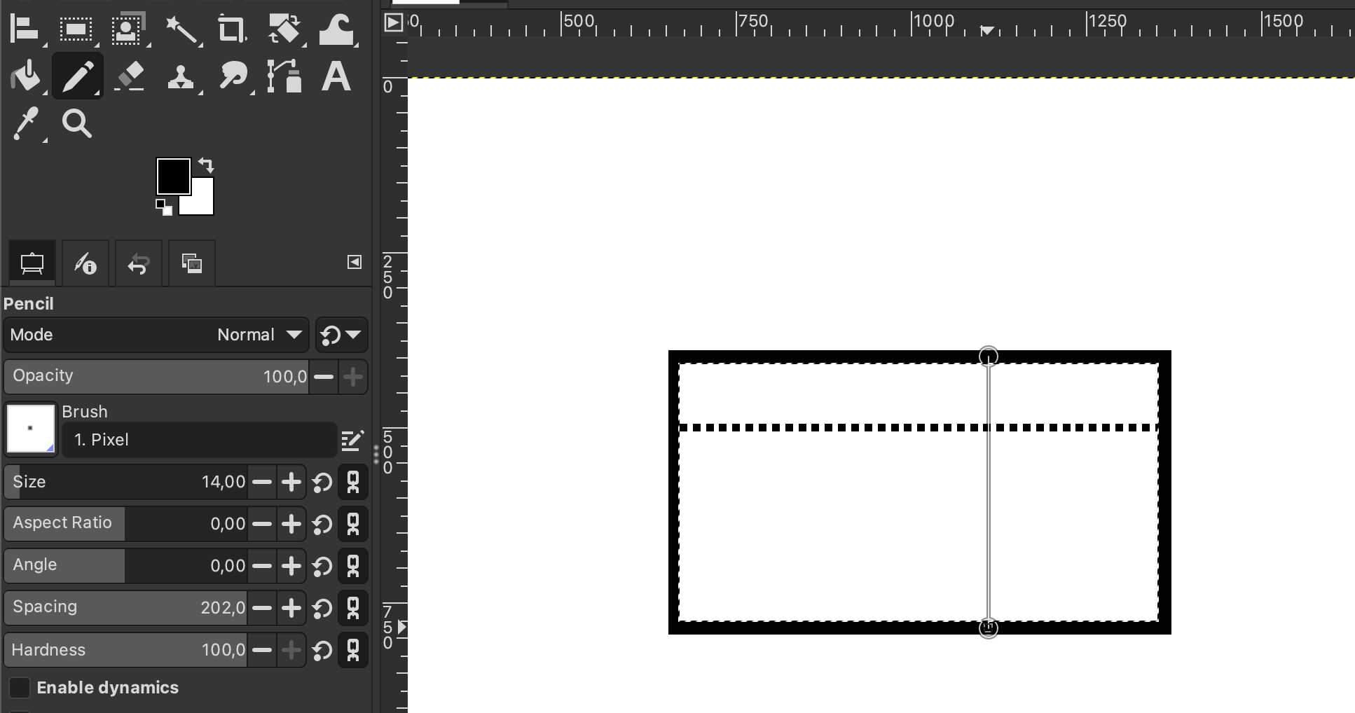
Using the pen tool and pressing Shift while clicking on the side of the rectangle, and again click on the other side, I was able to make a straight line. From Stroke style I chose a dashed line. I made two of those lines.
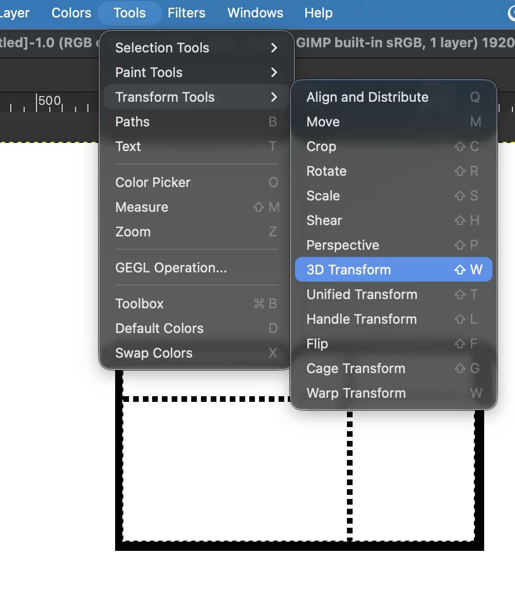
Then I did a 3D transfromation at Tools -> Transform tools -> 3D transformation ...
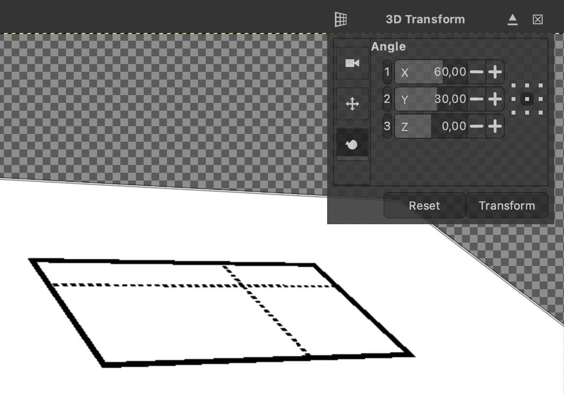
...and set proper values to make the image look like I want.
Then I created a new layer with Shift + Cmd + N on which I continue to draw non 3D transformed content.
For the pen, I screenshot the GIMP GUI pen and copy-pasted it on the layer, used bucket fill to color the background white and the pen black, and moved it to it's place.

Again on another layer, I created a "projector" with rectangle selector, bucket fill, rounded corners with the tool settings on the left.
Then did again 3D transformation for the "projector" and draw orange dashed lines with the pen tool.
Then I drew the remote connection symbol with the pen and copy-pasted it (with rotation) on the screen, which I had also drawn with same tools as the previous rectangle.
3D
For 3D modelling, Kris suggested me using Blender and Openscad. I also wanted to test one of the commercial softwares for which I’ve got the license. For that Kris suggested to try out Fusion 360. So here I document the use of these four software for 3D modelling: FreeCad, Blender, Openscad and Fusion 360 (if I have time for all of them). With each software I aim to do a basic model of the pen from the sketch above.
FreeCad
I began with freecad as our local lecture covered some of it. I also got help from this tutorial: 4 ways to do a cylinder in FreeCad.
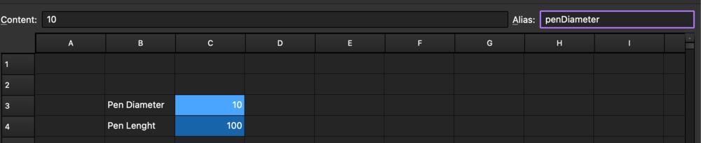
First I created a spreadsheet for which I was able to define the dimensions of the pen in variables to be used in the sketch, so that they can be more easily changed if needed. However, I remember this when I had already made the model, and used those simple numeric values instead.
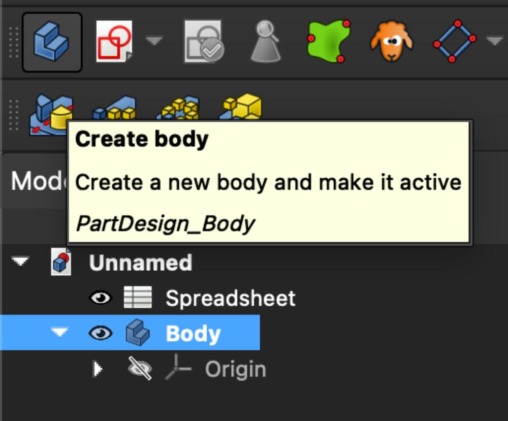
I created a body and checked that it’s active.
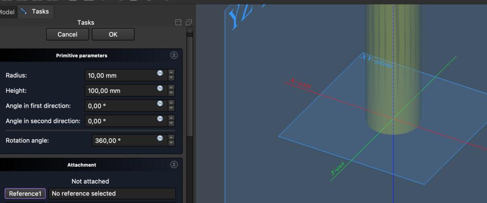
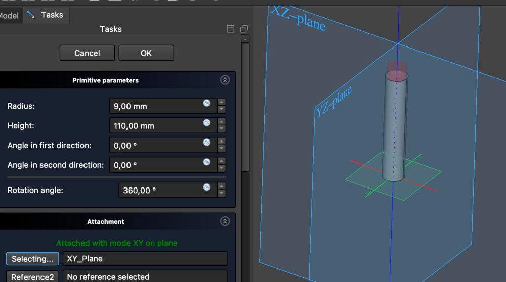
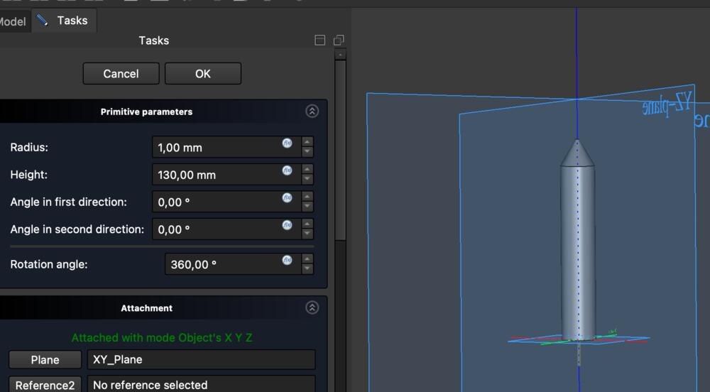
I had some weird problems with starting with a sketch so I skipped it and created an additive cylinder and set height 100mm and radius 10mm and reference frame as X,Y-axis.
Then I created a subtractive cylinder inside the additive cylinder on the same X,Y-axis with radius of 9mm and also made it a little higher so it can be seen on screen. Now I had a 1mm thick tube.
Then created an additive cone and moved it up 100mm along the z-axis to fit the top of the tube
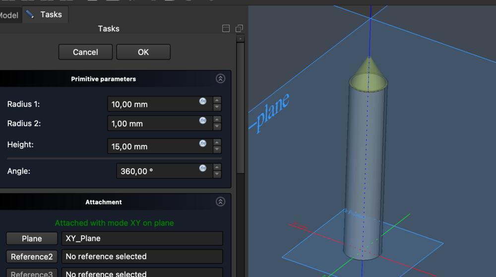
Created a subtractive cone to hollow the previous one and a subtractive cylinder to make a hole in the tip of the pen.
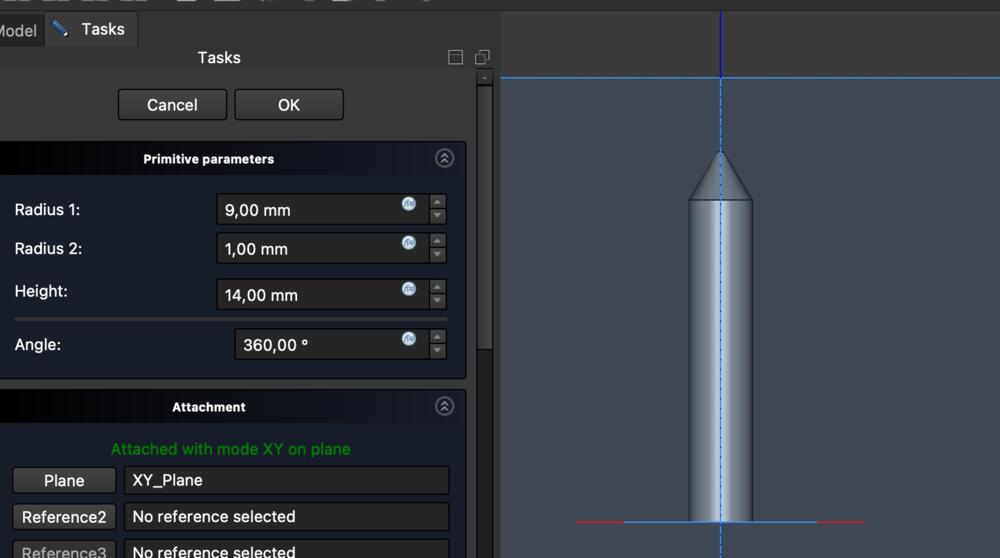
Created a 1mm thick additive cylinder inside the pen, -15mm along the z-axis.
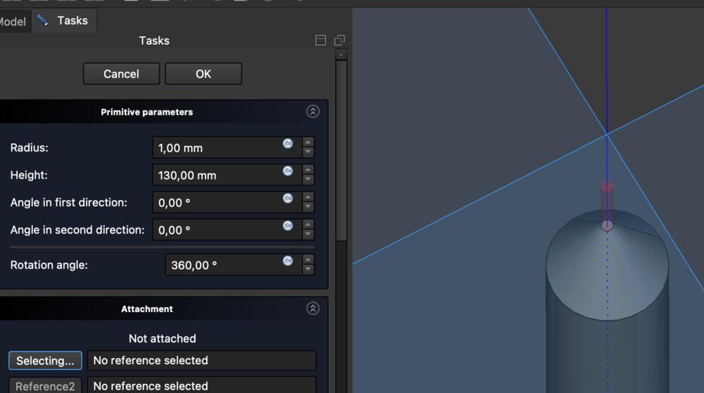
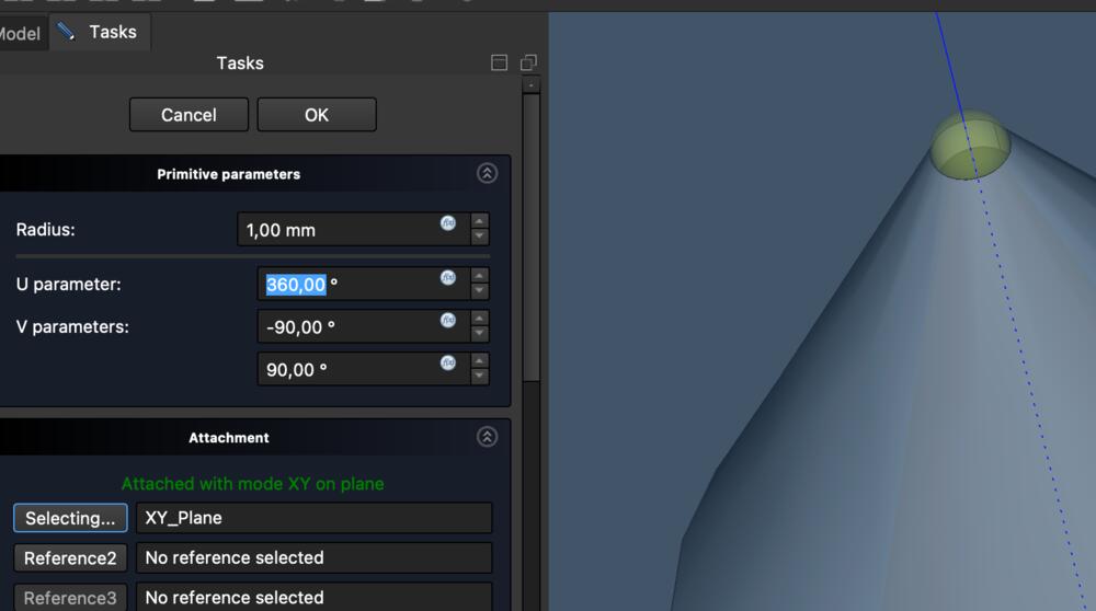
Then created a additive sphere with 1mm radius on the tip of the pen 115mm along the z-axis. This represents the pressure sensor and connects to the thinner cylinder inside the pen.
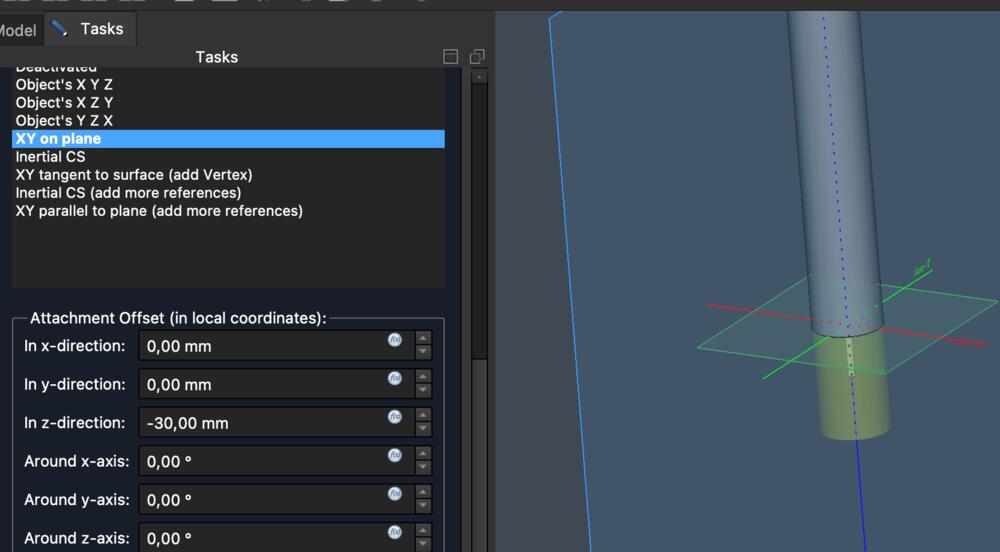
Created an end of the pen 30mm, -30mm on the z-axis which also attachs to the thinner inner cylinder. This piece is rotatable to adjust settings of the pen.
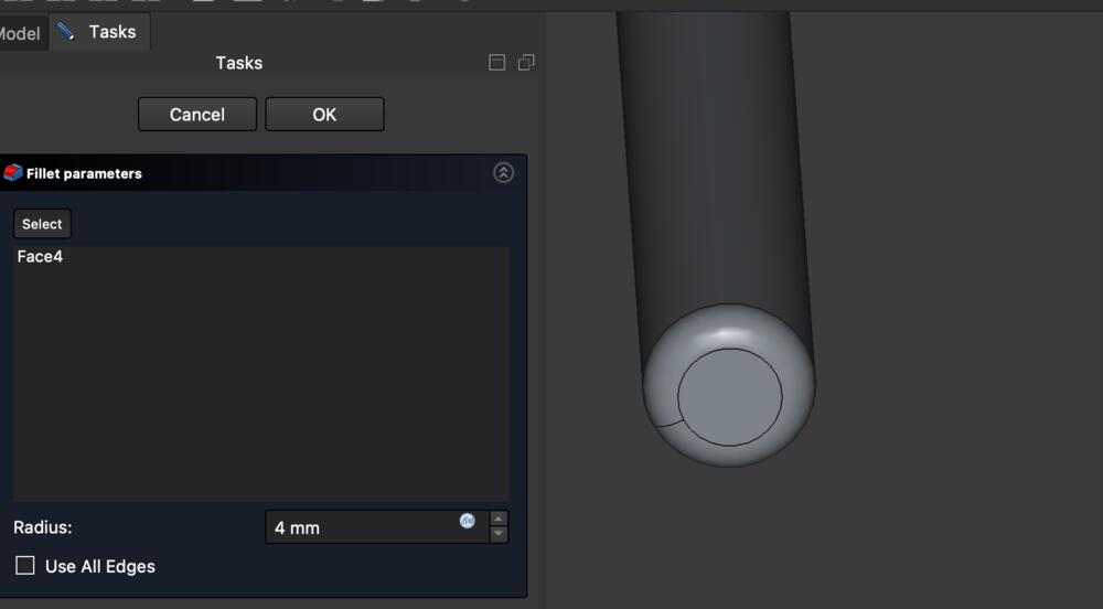
Also added Fillet to the end of the pen.
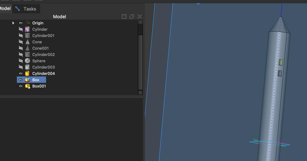
Made two Boxes as two buttons on the side of the pen
Blender
Openscad
Fusion 360
Learnings about documentation
I noticed this week as well that the documentation was being left to the end of week. However, I had taken screenshots while working on the modelling and written down text for the documentation (learned from previous week!), but the compilation of those parts into a complete documentation ended up being a rather tedious job anyways.
I discussed with Kris about having the website as the initial "go-to" documentation, and how to make the html so easy to use that I could use it for documenting directly on it. I figured that the main bottleneck was the compression of the files before adding them to the website. I began automating the cpompression process for which I added documentation to the Week 1 image compression section.