Week 4: Embedded Programming
The main outcome for the week
I made a simple space invaders type of a video game:
Design files made in these week are available at my gitlab repository
Soldering
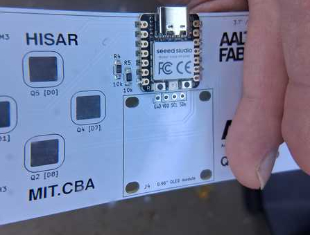
The first task was to make these components to work together:
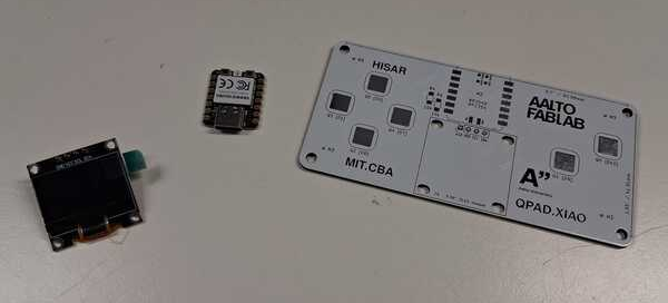
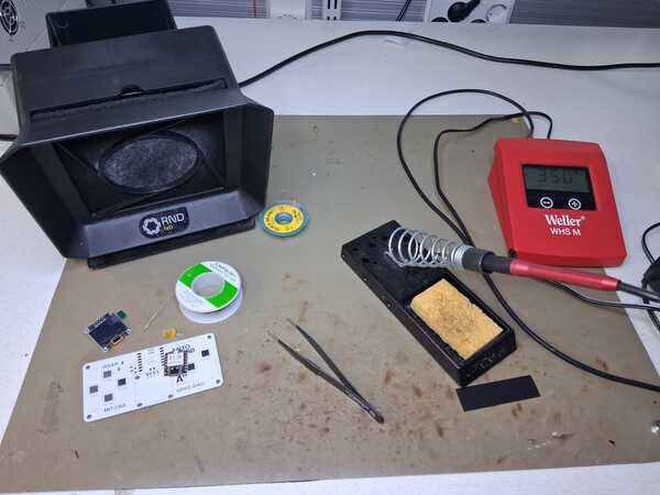
Set up for soldering
- the equipment ready: solder, tweezers, flux/flux pen, and desoldering rosin braid just in case (and the components of course)
- wet the sponge
- turn fume fan on
- turn on soldering station to 350 degrees (celsius)
- test the fan with little solder
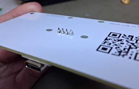
Soldered one side first of the resistor first. I dipped the heater in flux and spread it over the spot for soldering. There was still too little solder so I added it. The resistors were really small and it was quite difficult to get them on their place and straight enough. I had forgotten that I shouldn’t drink coffee before soldering: my hands were shaky (which got fixed by taking 100mg of L-Theanine to balance the effects of caffeine).
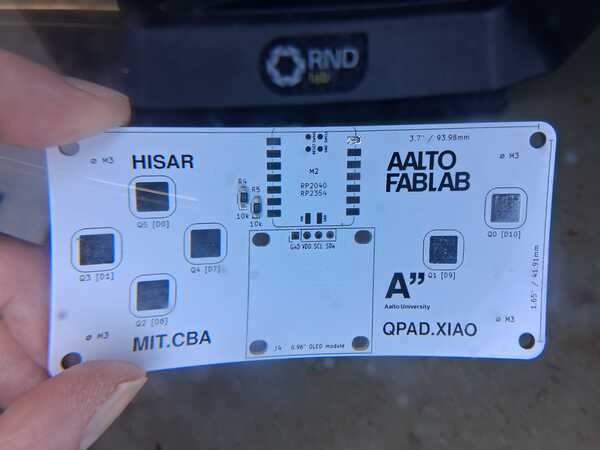
The microcontroller soldering:
Soldered the top corner first and then the bottom one on the other side to have it fixed on it's
spot before soldering all the final-project-others.
Again used some flux to clean up the spot. Later Kris showed that I can also mix up the flus
and the solder, by first dipping the heater in flux and the solder normally (but better results)
Added some more solder. Heated it again to attach the chip up but suddenly there wasn’t enough
solder, it sort of disappeared and I don’t know where.
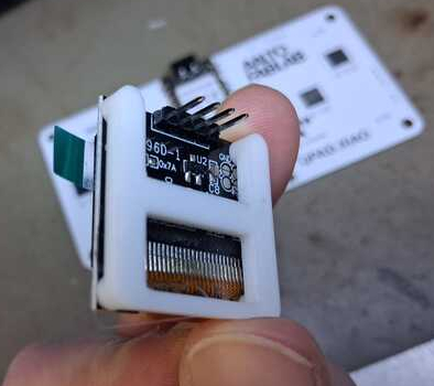
Then lastly I soldered the screen with it's spacer which Kris 3D printed in the beginning.
Microcontrollers
RP2040 with MicroPython
After having the soldering done, I continued to this MicroPython tutorial. I didn't take any screenshots because what I saw is pretty much the same as the images in the tutorial.
That started by installing and launching Thonny, an open-source IDE for Python. First I installed it in terminal, but opening it was somehow problemating so I ended up downloading the installer file and it's use became much easier.
Installing Thonny, I had an annoying problem of accidentally denying terminal access to Removable
Devices and couldn't
get Thonny to work, as it didn't ask any permissions any more (and sudo command asks password that I
don't know). Again, I turned to Gemini and was able to find a way to reverse that with command (if I
remember correctly)
tccutil reset SystemPolicyRemovableVolumes
Then again I had issue already in the beginning of the tutorial. (Why is so often that things don’t go as the tutorials expect.) I couldn’t find the disk on my Finder. Asked Kris and he gave me the solution: I had tp press B-button WHILE plugging the USB. Then I the MicroPython installer found the RPI-RP2 and I chose the variant of Rasberry Pi Pico.
The Blink tests were straightforward and successful. But then I ran into problems with The third one
when including the OLED into the program. It gave an error message that I couldn't figure out when
looking in to the code:
error "MPY: soft reboot
Traceback (most recent call last):
File "stdin", line 6, in module
File "ssd1306.py", line 110, in __init__
File "ssd1306.py", line 36, in __init__
File "ssd1306.py", line 71, in init_display
File "ssd1306.py", line 115, in write_cmd
OSError: [Errno 110] ETIMEDOUT
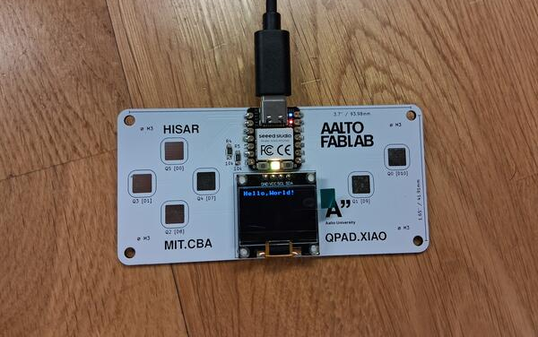
I asked Gemini about this and it explained the problem to be in the call for I2C isn't giving any response and suggested the most likely problem to be in the hardware, especially in the pins D4 and D5. This way I learned about how the pins are connected in RP2040 and the screen. The soldering seemed to be ok, so I did some code tests that Gemini gave, which, for example, proved that there is power and ground and D4 and D5 are somewhat connected. I tried a few other things until I looked really closely and realized that the D4 soldering wasn’t fully in contact with the board, which was probably the issue. I soldered it more robustly, and then the screen turned on blurry. First the code didn't work but suddenly there was the text Hello, World!
For some reason fixing a problem in hardware felt better in the end than fixing it in code. Also, this would be much more difficult without Gemini (or other LLM).
ATtiny412 with SAM D11C at Arduino IDE
Next day we moved forward to learn about programming ATtiny412 which was programmed using D11C programmer chip.
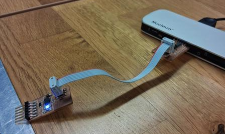
ATtiny412 is an AVR chip and Universal Programming and Debugging Interface (UPDI) is a protocol for programming ATtiny chips and has a single wire interface (only one pin). D11C is an ARM chip and is used as a "bridge" between USB/computer and ATtiny412's single wire interface. To allow this bridge, a core called megaTinyCore, which provides the toolchain to program ATtiny in Arduino IDE, needs to be installed in Arduino IDE.
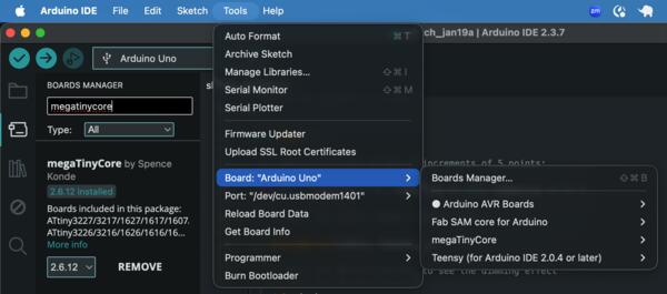
In Arduino IDE, I opened Board Manager in Tools -> Board: -> Board Manager (or just click the second icon from top on the left) and searched for megaTinyCore and Clicked Install.
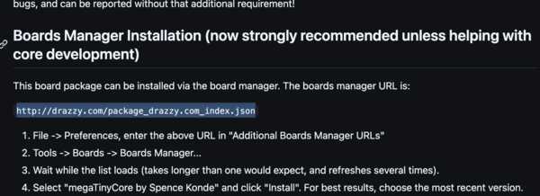
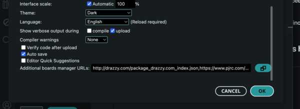
Then I went to Settings and added the URL http://drazzy.com/package_drazzy.com_index.json (copied from here) in to the additional boards managers.
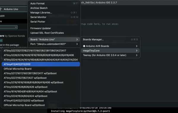
Then megaTinyCore was selected from Boards as shown below.
(I have no idea what are all the other
options there).
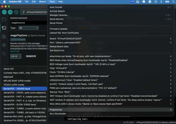
Then for the programmer, I chose the following SerialUDPI option.
Then I tested the whole thing with Blink-test which made the LED blink as coded. Blink test is the basic test to test if a microcontroller and computer/code has a connection.
D11C in Arduino IDE
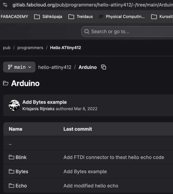
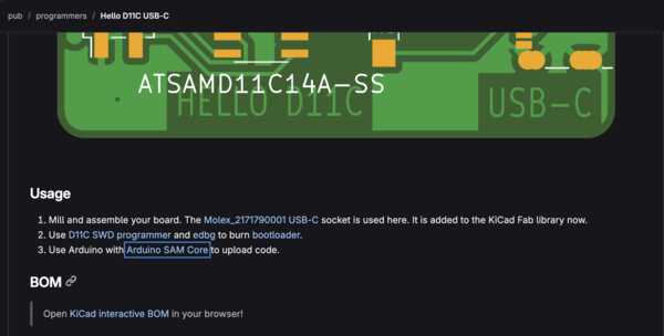
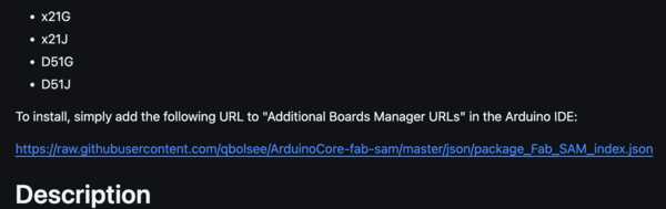
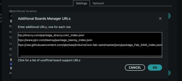
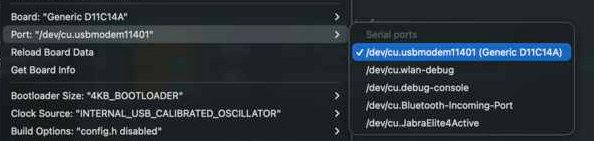
Then we moved on to set up D11C microcontroller and started from here, clicked the
third link that is active in the first image below, and there was the URL
(the second image) to be added to the additional boards manager URL list as done before (third
image).
https://raw.githubusercontent.com/qbolsee/ArduinoCore-fab-sam/master/json/package_Fab_SAM_index.json
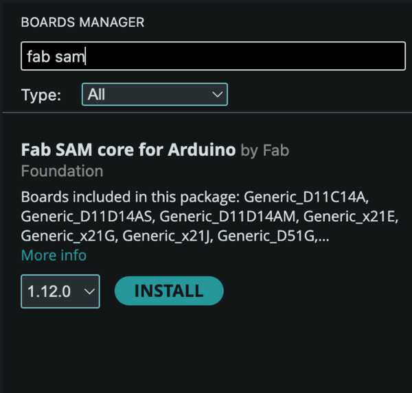
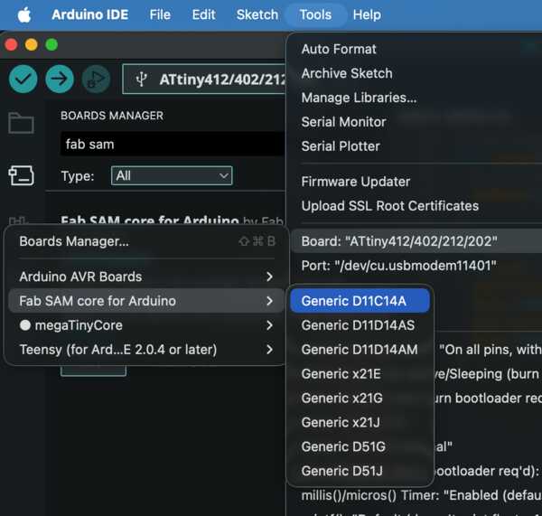
Below is shown the search and installation of the core for D11C, choosing the board, and choosing the right port.
Then I copy-pasted the code for Blink test (from here) and executed it, and it worked as supposed to: the LED was blinking
XIAO RP2040
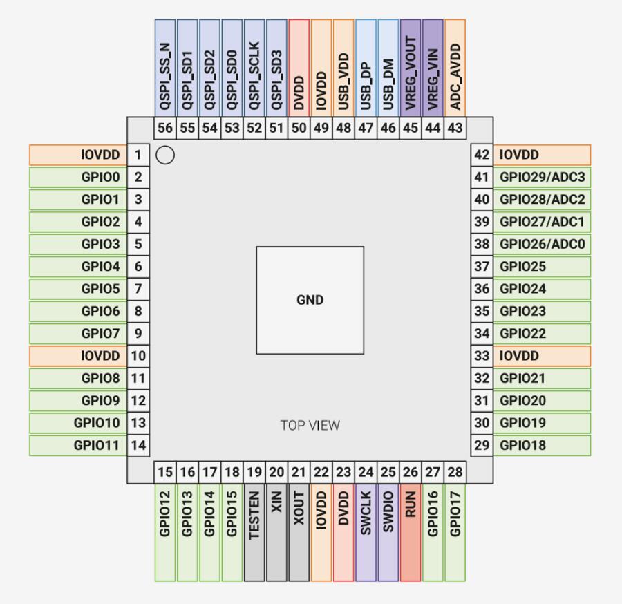
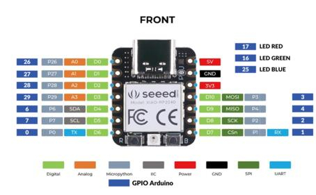
I chose to explore RP2040 microcontroller further as that is the chip used in our local lectures as
an example. To be accurate, we use XIAO RP2040 which has the same chip as in the RP2040
datasheet but includes also USB-C, 2MB Flash memory, and some leds included on top of the actual
chip. XIAO RP2040 does not provide acces to all of the RP2040 30 pins covered in the datasheet, but
has 11 pins. Left side is RP2040 pin map and on the right is XIAO RP2040 pin map.
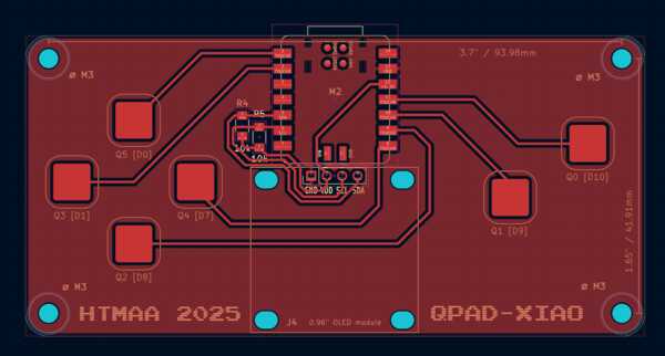
Here are shown how the pins are connected within the QPAD (source: Quentin Bolsee).
RP2040 Datasheet
Began to go through RP2040 Datasheet. Browsing through the table of contents, I didn’t know most of the words, terms or abbreviations in there, some of them was familiar but didn’t know much about them, which only emphasized how much I don’t know, and probably should learn. There was an initial feeling of overwhelm. Kris gave me a tip: start on what I already know, even distantly, and build understanding from there.
I, however, used Gemini to break down the most important parts for a beginner, but I didn't want it to explain all of it so that I would be familiar with the data sheet as well and to learn to read that type of text. Gemini helped me in focusing on the most important parts to begin with. It suggested to go through the introduction (chapter 1) and pinout reference (1.4); Single-cycle IO (SIO; section 2.3.1) as it is the most commonly used in basic programming; Peripheral (chapter 4) insofar as I'm using each, for example I2C; and Bootroom and UF2 (2.8). It also mentions that PIOa are often the reason to choose this chip: they are smaller programmable units outside the main CPU and can handle smaller specific tasks.
While reading the data sheet, I began writing down the main things so that I can explain them to myself later. I didn't go far as I found the overview system image of the chip, and asked gemini to explain it to me, which was really helpful. Learning the abbreviations was important as they were one significant source of overwhelm. I ended up spending almost two hours delving into the image with Gemini's explanation of the abbreviations and their functions and asking further questions. I ended up writing the following summary (by myself, for myself as a learning experience).
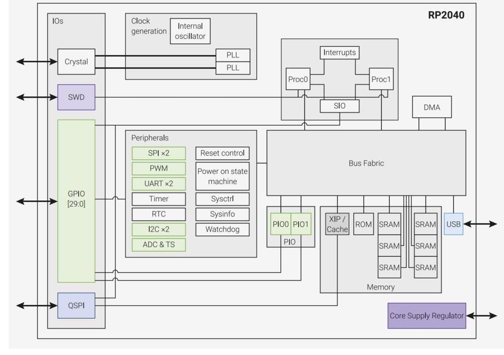
Processing:
- Dual Cortex-M0+ cores: two processors (Proc0 and Proc1) which can divide tasks between each other.
- SIO is single-cycle input/output: a direct connection from pins to processor (and other way around).
- Large volatile memory capacity (forgotten when power off), 264kB SRAM (Static Random Access Memory) in 6 banks, which allows for access in multiple memory locations at the same time.
- No non-volatile memory (storage), but there’s support for external Flash memory via QSPI (Quad Serial Peripheral Interface).
- XIP act as a cache between to work faster for the processor.
- ROM is for starting up.
- 30 GPIOs: these are (general purpose) pins that are connected to the main processor, and their functions are shown in Table 2. GPIO Bank 0 Functions (which I can’t say to really understand)
- Pins 26-29 can act as analogue pins (connected to ADC), meaning they intake any voltage between 0 and 3.3, whereas fully digital pins are either or.
- Peripherals has specific purposes and work between pins and processor(s). I2C, SPI and UART are for specific uses and can be used with each of pins (as assigned in code).
- PIOs (Programmable Input/Outputs) are able to handle the data as programmed independent of the main processor and handles timing.
- USB used for direct connection to computer.
Others:
- Over 3.3V should not be used for not to brake the chip. Core Supply Regulator reduced voltage to the used 1.1V inside the chip.
- SWD allows acces while program is running, e.g. for debugging.
- DMA allows acces to memory without processor effort, e.g. for data to be moved in memory.
- Clock provides a stable pace (binary wave of 0V/3.3V) inside a chip so that everything happens in synchrony. (RP2040 runs at 133MHz = 133 000 000 “ticks” per second). Crystal oscillator makes this more accurate. A cycle in SIO is the time between these ticks.
- Bus Fabric routes addresses and data across the chip.
I wrote down the my overview based on Gemini’s answer and then asked Gemini if everything is correct and what should be added/what’s missing? Then I added some things such as informations about I2C, SPI and UART and PIOs handling timing, and USB connection. Going through all this with Gemini allowed me to learn things about electronics and microcontrollers that were not taught in the datasheet but was expected as preliminary understanding. This also reminded me well about the basic building blocks of computers in general and how they work together. Going through the datasheet without this understanding would have been somewhat useless, but now I also studied the datasheet while learning basic stuff.
I continued going through the data sheet while keeping open the overview image for reference. I still didn't understand much about it, I skipped most of the tables, especially the registers, and quite soon gave up as reading the data sheet didn’t seem very fruitful (it was quite late already).
I probably need to focus more on SIO, GPIOs and peripherals to understand more of the actual use of the chip.
Programming a game with XIAO RP2040
My goal is to program a simple Space Invaders game to be played on QPAD. A file named main.py saved in RP2040 is starts automatically when power is turned on, so that is the name of my game file.

I started programming with a template which Kris used to demonstrate the screen and it can be seen here. I went through the template to understand how does it work. I opened all the libraries that are imported in the code to better understand their use. I had downloaded them earlier when doing the tutorial.
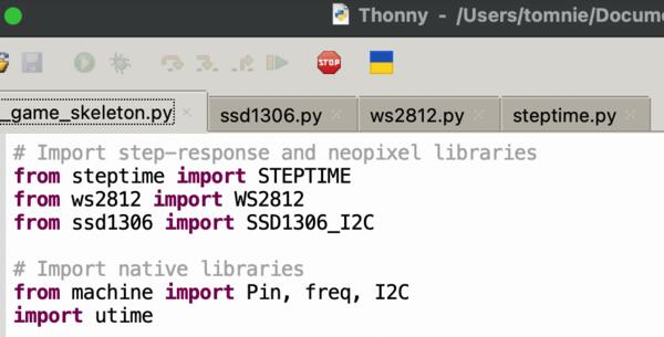
- ssd1306.py is helping in controlling the OLED screen.
- ws2812.py is used to control LEDs.
- steptime.py is apparently used to activate the controls on the QPAD.
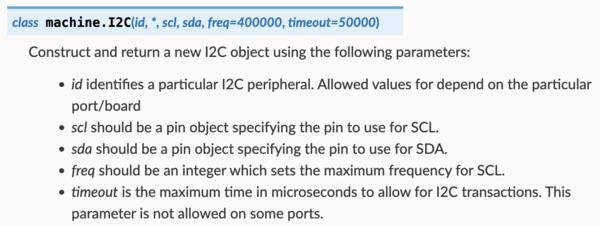
I also opened machine library documentation in MicroPython documentation:
- Pin-class is used to control pins: the mode in the code set as either Pin.IN or Pin.OUT.
- Then there's Pin.PULL_UP and an id. More about the constructors here.
- I2C-class is used to set up the connection to the OLED screen.
- Freq- function in this code is used to set the frequency (needed for steptime library).
I figured I need to create a class to save the height (position on Y-axis) of the plane and allow changing it. Thus I created a Spaceship-class with a value for height.
Soon Thonny gave me this error:
- Device is busy or does not respond. Your options:
- wait until it completes current work;
- use Ctrl+C to interrupt current work;
- reset the device and try again;
- check connection properties;
- make sure the device has suitable MicroPython / CircuitPython / firmware;
- make sure the device is not in bootloader mode.
With the help by Gemini I realized that it’s stuck a loop and it can be quit by tapping Cmd+C multiple times. I began creating log prints for quick debugging.
I managed to modify the skeleton code so that the top left “button” on QPAD moves the plane up. The plane was a simple “>” shown as a text. I had to make it move a bit faster: from 1 to 2.
I kept having trouble that the chip didn’t respond, only showing the red light that is initiated in the beginning of the code. I had it being turned to yellow in draw_character-function to signal that the program is drawing. I kept disconnecting the USB which worked at some point. The Shell was showing the same error message in the I2C-call that I had had in the tutorial with weak soldering. I wonder if the soldering have been “damaged” when the USB had been removed and put back. I tried wiggling the components and it started working. I probably should solder some more.
Making the ship move downwards, I didn’t understand the channels-list given in the code. The top left button was being checked with ”if channels[0][4][0]”. I began just quessing what might be the if-statement for the left bottom button. The id for it was 2 which shown in the configuration of the buttons.
But to save time and effort, I simply asked Gemini to explain the “channels” list variable for me. It became clear (obvious) fast and I also understood how to interpret and use it in the future. I hadn’t understood what is STEPTIME in there and what is reduntant as I’m reusing the code. The table below was enough for me to start making sense of it and I didn’t want to read more of Geminis answer but rather figure out things by myself.
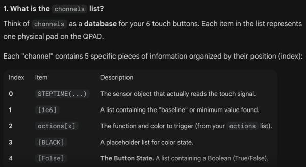
Channels[2][3][0] simply refers to third row/list (with button id 2), and fourth list inside that row, i.e. FALSE or TRUE (if button is pressed), and the last [0] to the only element inside that list.
BUT, for some reasons it didn’t work. I tried it with middle left button and it works. This must be a hardware problem again (-> soldering). But now I had the ship moving up and down, with slightly unintuitive controls.
Then I created a shoot method inside the Spaceship class and added another if statement for a button on the right (channels [5][4][0]. I wasn’t (yet) sure how to make bullet that moves across the screen so I made it a static “laser” and think about it later. Maybe the laser is more adequate in this course.
Then I moved on to creating the Invaders: I created an Invader class as there are many of them that have independent locations. For increasing difficulty, their number need to increase as they are being shot. They also need to explode to create satisfaction for the player.
I decided to take a short cut and increase the number of invaders on each level, i.e after a bunch of invaders has been shot. Even then thinking of how to increase the number of invaders in a simple manner was surprisingly problematic (it was getting late again…). I just did one solution which is probably not very optimal but the goal is to make the game work. For this purpose I wrote the check_level-function. There was some errors to fix and then debugging all the levels in the function, counter, and “>” and “<“ -signs. For example adding “global” in front of a global variable if referenced inside a function. I replaced ">" and "<" -signs with==if applicable to prevent any confusion in them.
Next phase was about changing all the other code to support multiple invaders. This included adjusting the Fleet class and for loops to go through the invaders in a fleet. This included many smaller changes and adjustments.
When only trying to fix the end text and restart, I had to again turn to Gemini and asking for a debug. One bug was that I had the coordinates for text wrong, x values in y and other way around, and the other one I probably couldn’t have figured out: the process_touch() updates the buttons and that had to be ran before giving option to “press any button to restart”.
Now managed to get the restart working and here’s the game:
I took a demo video using Quicktime Movie recorder, converted the resulting .mov file to -mp4 and compressed it using ffmpeg as described at Week 1 and then edited it with KdenLive cut and removed the non-esssential parts of the video and with razor tool clipped the video in parts and increased speed for the play parts by right-click -> Change Speed -> 300% and then rendered the video into .mp4. Compressed again as some settings in Kdenlive made it larger, got to check them later.