Week 09: Output Devices
The main outcomes for the week
I designed and made a PCB that makes a servo motor move.
Design files made in these week are available at my gitlab repository
Servo motor -PCB
My plan for this week’s project is to make a servo motor to run based on input from ToF proximity sensor: the board I made last week. The motor should move clockwise when my hand approaches the sensor and counter clockwise when moving away.
What is needed for the board:
- FFC connector to connect to ToF board (from previous week)
- A new XIAO microcontroller to test communication between two boards
- Level shifter is used to ensure correct voltage for the servo motor PMW signals. For level shifter also two small capacitors and resistor is needed.
- 1x3 connector to connect the servo motor
Electronics design
After Kris explained the workings of servo motor, particularly PWM, and level shifter, I started to draft the board on Kicad Schematic editor. I used Kris’s RotoStage project as a reference on how to use level shifter, specifically the schematic of it.
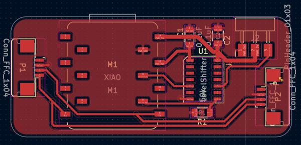
To make documentation a bit more straight forwards here, here’s an overview image of the initial schematics that I created.
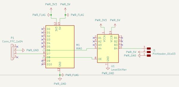
I asked Kris to check whether everything is correct, and he pointed out that I had forgotten to place the capacitors (obviously). Two other things were the pull down resistor and connection back to the ToF board (to do also the assignment for the next week with this set up). So I added those.
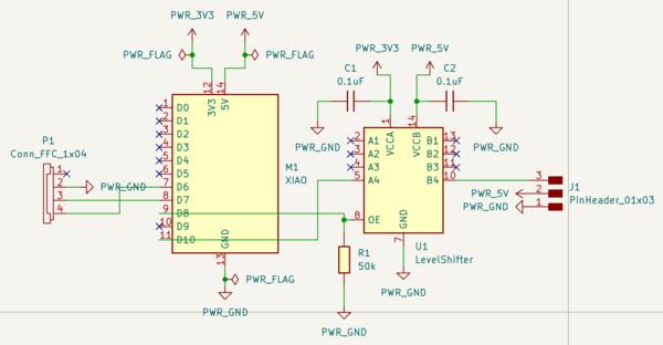
Schematics explained starting from left:
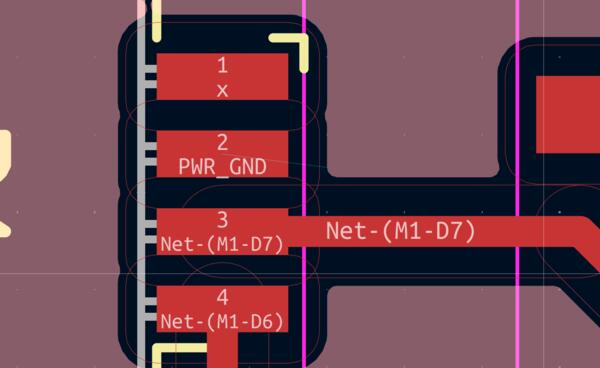
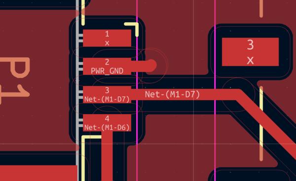
FFC connector receives the four tracks from the previous week’s board. As there’s another XIAO (XIAO 2) here, there’s actually no need for the 5V input, so that is left crossed. Then there’s a connection to Tx pin which will be used in next application used for networking and communications assignment. That was connected to Rx pin in the other XIAO (XIAO 1) board.
XIAO Generic (XIAO 2) provides the voltage and grounding as well as program for translating the signals received from XIAO 1 to signals usable for the servo motor. These signals are sent out from pin D10. Pin D8 toggles the level shifter on or off for which the pull-down resistor ensures the pin recognizes the change from HIGH to LOW.
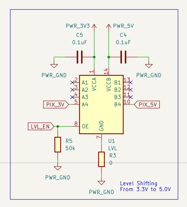
Level shifter is used for translating the 3.3V PWM signals send from pin D10 to 5V. The 5V provided by the XIAO is used for running the motor (no need for level shifter) whereas the PMW signals communicate the angle for the servo (based on the width of a pulse) from a regular XIAO pin, thus the need for level shifter. Also, there are two small capacitor that ensure a stable current for the level shifter and the servo.
Level shifter pins work as counterparts for the pins on the other side (A1 with B1 and so on), but are translated from lower voltage put in VCCA to larger voltage provided by VCCB. What is put in to A1 happens at B1 but in higher voltage. OE (output enable) toggles the level shifter on if HIGH, which can be constantly high if connected to 3.3V or toggled by the MCU if connected to a controlling pin (and then a pull down resistor is needed).
Servo motor is connected to the connector on the right which has the (level shifted) signal control pin, 5V for running the motor, and ground. These three connections needed to be placed corresponding the integrated wiring of the servo motor.
Then I moved on to PCB Layout Editor. The pinheader looked wrong on the layout and I realized I had chosen vertical instead of horizontal. I changed that because I like horizontal more.
Now I remember to set the net classes before starting the routing. As I routed the power tracks, I made them wider by clicking the track, pressing U to select all of it, and pressed E to open the edit menu where track width can be set. For 3.3V I set 0.6mm track width and 5V I set 0.8mm track width.
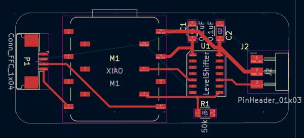
I added Fill Zones connected to GND. For some reason the ground in the FFC connecter wasn't connected to the Fill zone so I made a manual connection for it.
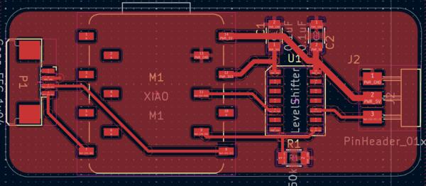
And the board looks like this before exporting it to gerbers:
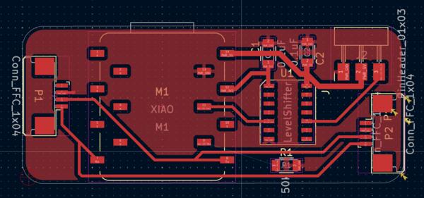
But then I came back and added one more flat cable connection to be able to test how the addresses work in networking. The plan is to use the sensor input to two outputs for networking assignment (next week) and for that I will print two of these boards.
Electronics production
Trying to open this on coppercam I didnt’ get the confirmation if the highlighted path is the contour. Thus I wasn’t able to add design tabs or much of anything. So I came back to KiCad to make the board a bit larger to test if that would solve the issue as some components were outside the edges and there was no fill zone on the bottom edge.
Then in the export menu I noticed that there was 5 violations note in the bottom left corner. I ran the ERC and checked the other tab, unconnected items, that I had not given notice before (and apparently didn't take a screeshot of), and there I found that I had not connected the pin 9 to the resistor and OE pin on the level shifter. Also there were two (other) grounds that had not been connected to the zone fill so I connected them manually. Then the board looked like this:
I re-exported the gerbers to the Bungard machine. It didn’t work solve the contour problem.
I tried remaking the edges on KiCad. It didn’t work.
It only worked when I made a simple rectangle edges.
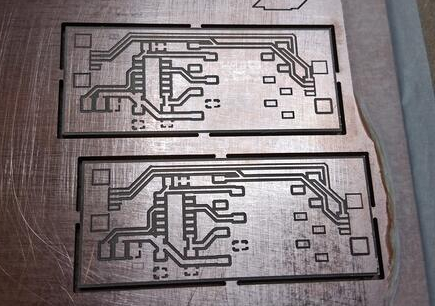
The milling process was straightforward but I still checked everything from Aalto wiki. The PCB material was again jumping when being egraved, but now I had a cover tool around the milling bit to press it down.
End result was good quality:
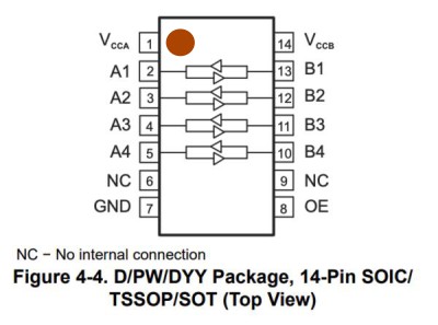
I began soldering from left to right but I should have started with the level shifter as it’s really small and quite close to the XIAO´s socket. When I came to solder the level shifter, I wasn't quite sure which way it should be placed on the board and the datasheet (with the image below) wasn't very helpful. There’s a dot on one of the corners of the level shifter (too small to take a phot easily) and according to Gemini that is the Vcca pin. I decide to trust Gemini and it turned out to be correct. I added a red dot to the image below.
Also, it was the first time I was using capacitors and wasn't sure what voltage I should choose as we had 100V and 250V. I asked Kris and he said that 100V is good but it doesn't really matter (as I though myself too). Also, I didn't know if these capacitors were polarized or not, so I asked about that too: these small ones are ceramic and not polarized, i.e. no difference which way they are placed (large round ones apparently are polarized).
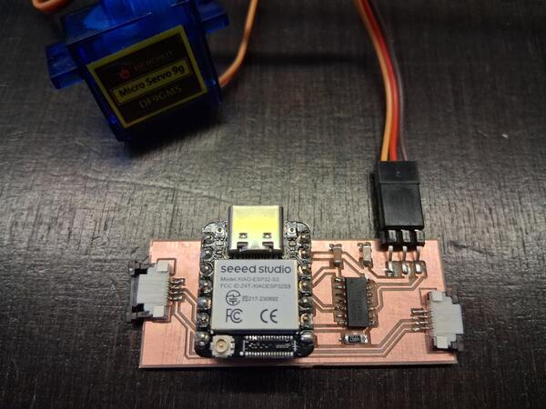
The soldered product looks like this. I'm starting to feel quite confident with my soldering and actually like it. Having thinner solder wire, using flux pen and rosin on every footprint, and letting the solder flow nicely before lifting the heater, have made a difference.
Programming
To initialize the ESP32-S3 microcontroller, I followed the same process as in the previous week.
- I had the CircuitPython firmware .bin-file downloaded from here
- I put the XIAO in bootloader mode by pressing BOOT while connecting
- I flashed the firmware with the web tool by setting offset to 0x0, uploading the .bin file, and clicking program.
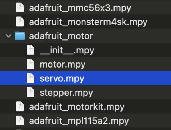
- From the adafruit library bundle I searched for motor library and from there I added servo.mpy to the XIAO's lib-folder. (documentation of the library). This translates the angles to the servo quite painlessly.
Then I opened Thonny to begin coding. For reference, I used Adafruit's learning materials.
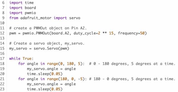
I went through the pwmio library and I made sure that I understand what's happening in the code and saved in in the code.py in the XIAO and ran the program: nothing happened with the servo and there wasn't any error message.
I realized I had plugged the servo wires in wrong way, as in the image above. I wonder if that has destroyed anything, as changing it won't give any result either.
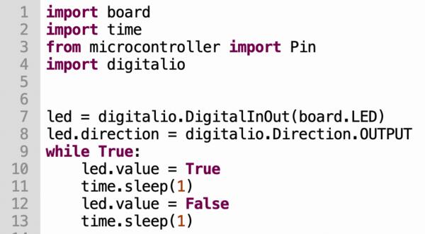
I was able to make the XIAO led blink with the code below.
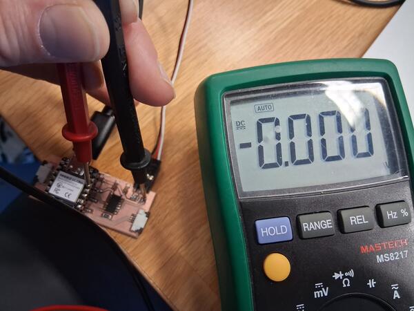
I took a multimeter in use to check the connections. It seems that the level shifter is not working as I get 5V normally but the 3.3V is not converted to 5V and shows nothing on the other side of the level shifter.
I asked Gemini on how to check what's wrong with a level shifter and it mentioned OE pin. I realized that I haven't in the code given the OE pin the signal to turn on the level shifter, as I only used the example code. I changed that and it still didn't work and I couldn't get 3.3V out of the OE pin. I checked them again and realized I had wrong pin activated in the code. So I changed that, and it still don't work. I can't get 3.3V out of the pin connected to OE. I ask more from Gemini and tried out using different pins in the code as it wasn't clear which names does CircuitPython use for the XIAO ESP32 pins.
Kris came to help me and told that you cannot measure the 3.3V from the OE pin because it's PWM: it needs logic analyzer to check the signal. He first tested a few other things, then used multimeter and semi-accidentally pressed down the level shifter and the servo started running.
So the issue was a cold joint somewhere with the level shifter. The problem was probably the pin that I had already resoldered as it looked suspicious but apparently not well enough. After resoldering I was able to make the servo run properly.
In the next week I continue to combine the input and output devices that I've been working for these last two weeks with communications between different boards.