Week 12: Computer-Controlled Machining
The main outcome for the week
This week I designed a shelf with FreeCAD and CNC-milled/cut it in reality. It is designed to be attached to my electric desk at home so that it goes up and down with the desk (so that the desk still works and won't break).
Starting point
For this week I have 120cm x 120cm large plywood (thickness 15mm) of which I need to mill something useful. My workdesk at home is often quite a mess and is quite difficult to keep in order. I think having a shelf on it could make keeping it organized much easier. So I want to make a shelf for my home workdesk. The desk is 120cm wide so there can’t be one horizontal piece of shelf from left to right because the dimensions of the plywood.
Requirements:
- I want the shelf to be attachable to the desk and that it’s sturdy enough to be used without glue or other adhesives.
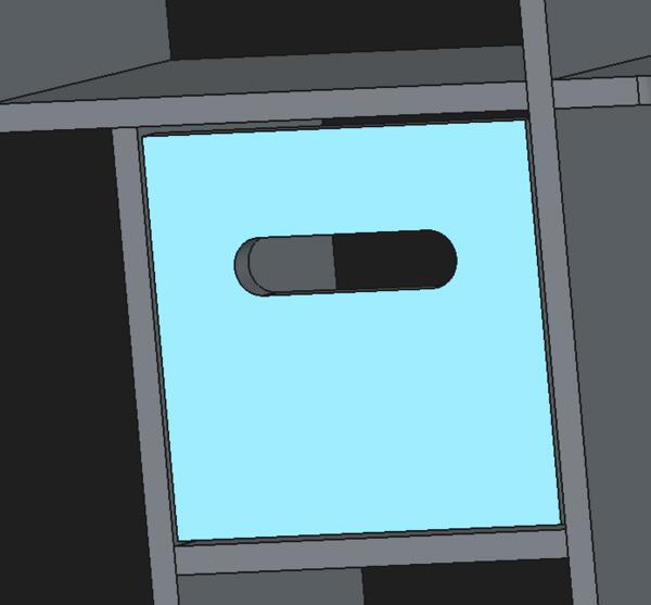
- I have a screen in the middle that I want to be embedded in the middle of the shelf to maximize the are in front of me. The screen is 53cm wide and 40cm high.
- I also have a wide loudspeaker that could be fit under the shelf. That is 95cm wide about 11cm high and deep.
I have some idea what the shelf could look but it’s not exactly a complete idea.
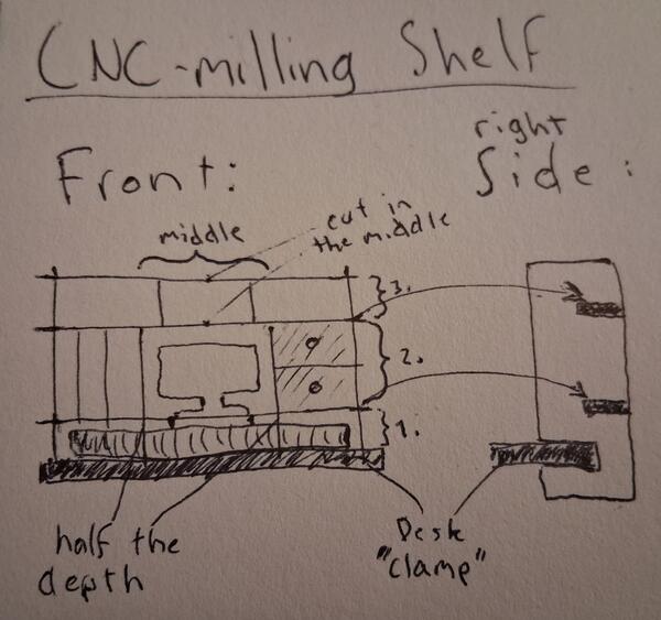
Modeling on FreeCAD
I began by sketching the idea on my notebook. It was quite rough and I decided to work the details in FreeCad for not to spend too much time trying to draw the joints and dimensions. I watched again the lectures (global and local) to be more informed on my decisions. My idea was to use cross halving joints for the larger pieces and mortis/tenon joints for the smaller middle pieces. I googled alternative wood joints for shelfs anyways. There are a lot of ways to make it much more beautiful shelf but I don’t want that to slow me down from just starting. This is just plywood anyways.
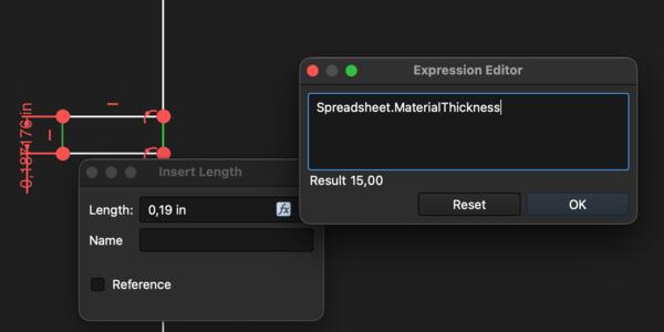
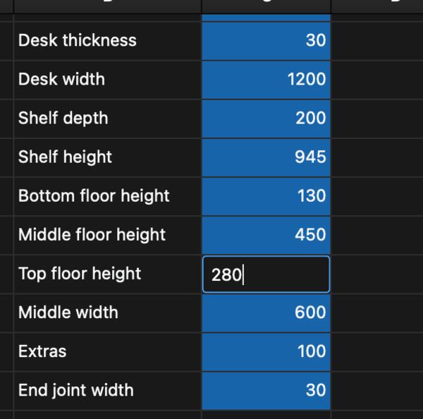
Then in FreeCad, I began by creating a spreadsheet and defining the dimension variables on it.
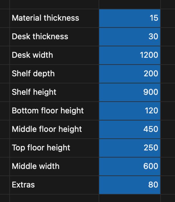
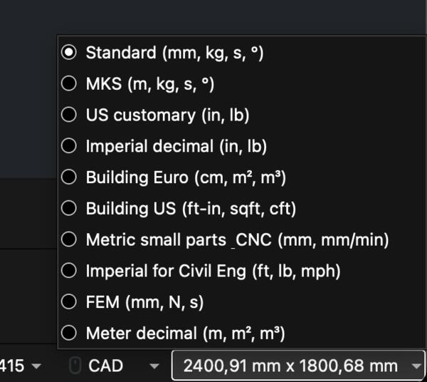
When I began applying the dimensions I realized that FreeCad was using inches as units. I didn’t remember how to toggle that so I searched for it and it was as easy as Preferences > General > Units > Standard. They didn’t apply however, so I restarted the program, but that didn’t work. I tried make the sketch again, but that didnt work. The, I happened to see inches in the bottom right corner and selected Standard from there and that made the change.
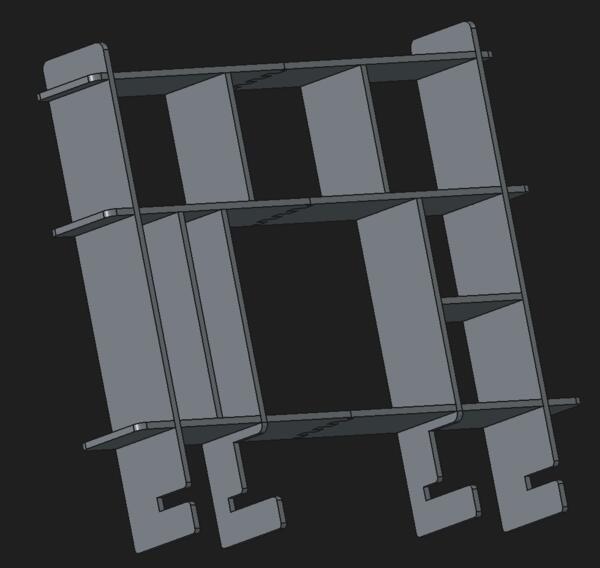
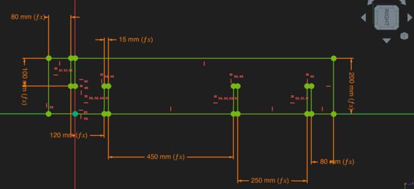
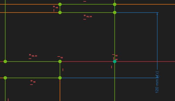
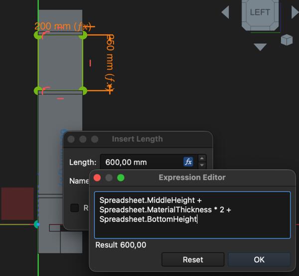
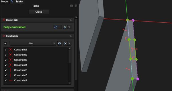
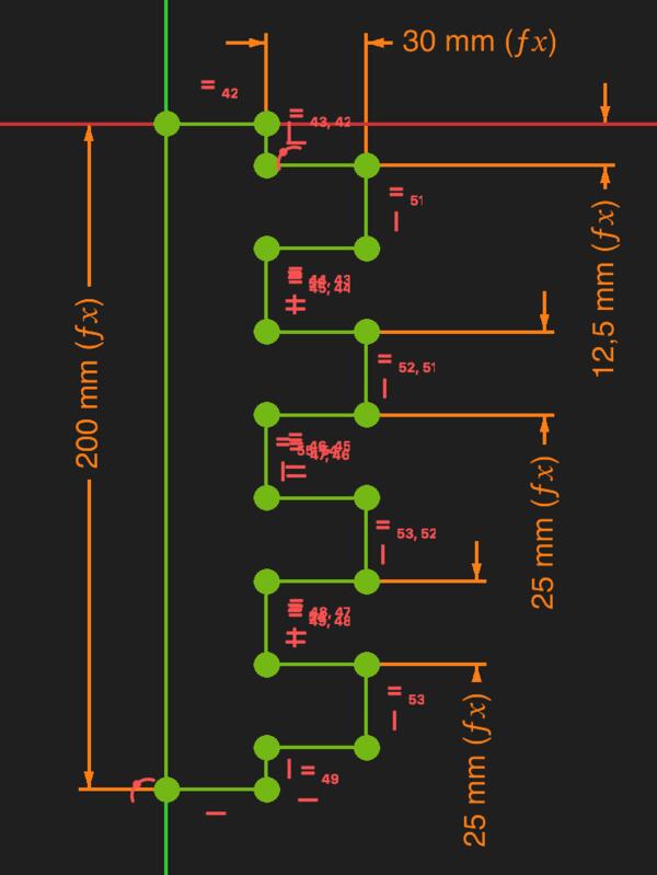
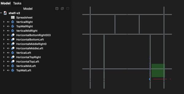
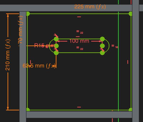
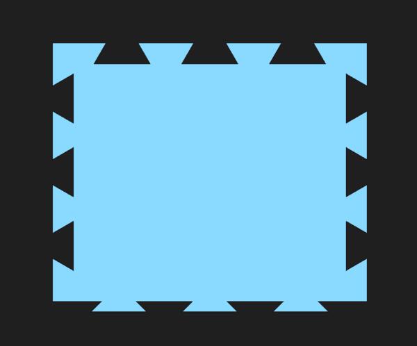
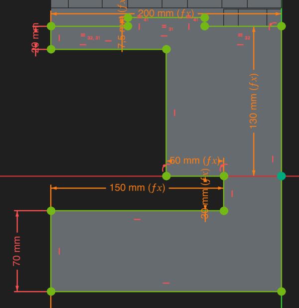
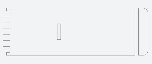
After applying all the dimension variables, the sketch looked like the image below.
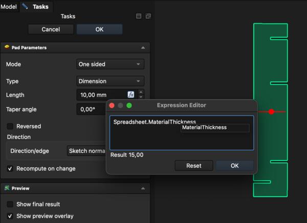
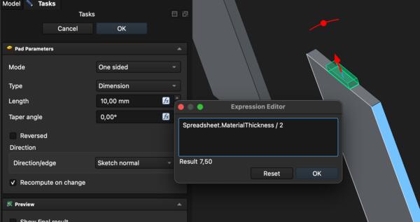
I made a pad out of the sketch as thick as the (plywood) material.
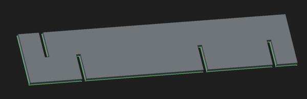
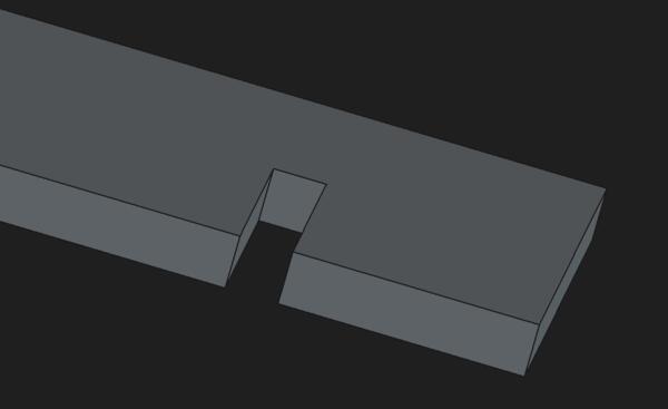
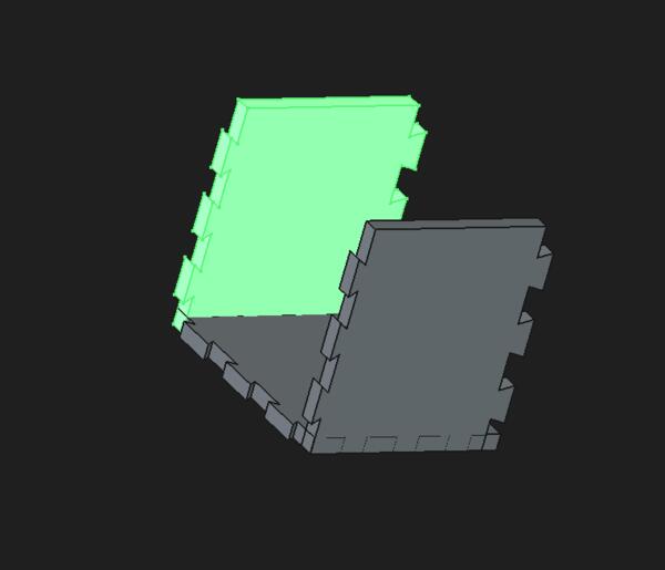
Now looking at the pad, I realized I had defined the cross halving, that is supposed to attach to the desk, to be the thickness of the material instead of thickness of the desk. So I went back to Sketcher and fixed that. Now the piece looked like this.
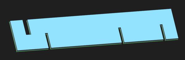
I renamed the body, then copy-pasted it on the tree view and selected everything. I went to the sketch of the copy and removed the top part of the piece. Here I also noticed that I had set the bottom height wrong: it was supposed to be from the top of the desk and not under it. I corrected that also on the first part.
Like this:
Not like this:
Looking at the 3D pads, I realize that the upper part of the second piece should have more depth, as it’s only the bottom part that needs to have space for the loudspeaker. So I fix that in the Sketcher. Having an overall sketch on my notebook, although a rough one, is clearly important at this point as I’m constantly checking the adequacy of the 3D model from the sketch.
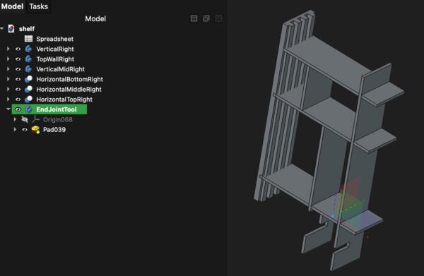
I decide then to continue sketching the horizontal pieces. The pieces are connected in the middle with finger joints as they are easy to cut and keep the pieces attached. I added EndJointWidth parameter into the spreadsheet. Then I started thinking that those might not be the best for this purpose so I searched Google: joint for connecting two horizontal panels? It recommends finger joints. Then I asked if there are other ways to make a plywood longer.
It seems that the best options are these:
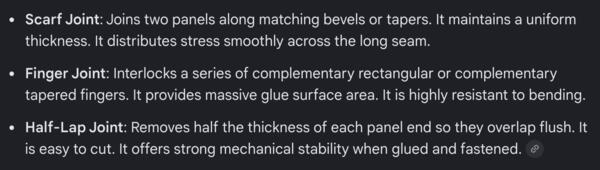
(Also one option would be to use a butterfly shaped pockets and pieces to join them together.)
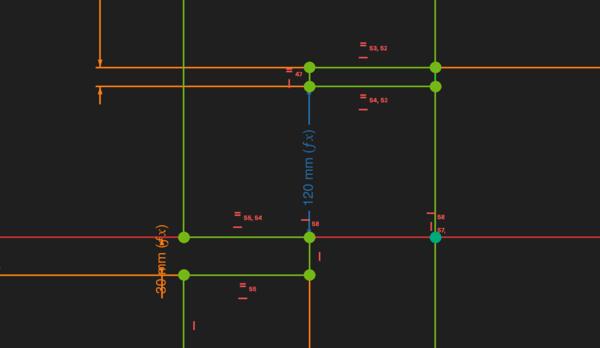
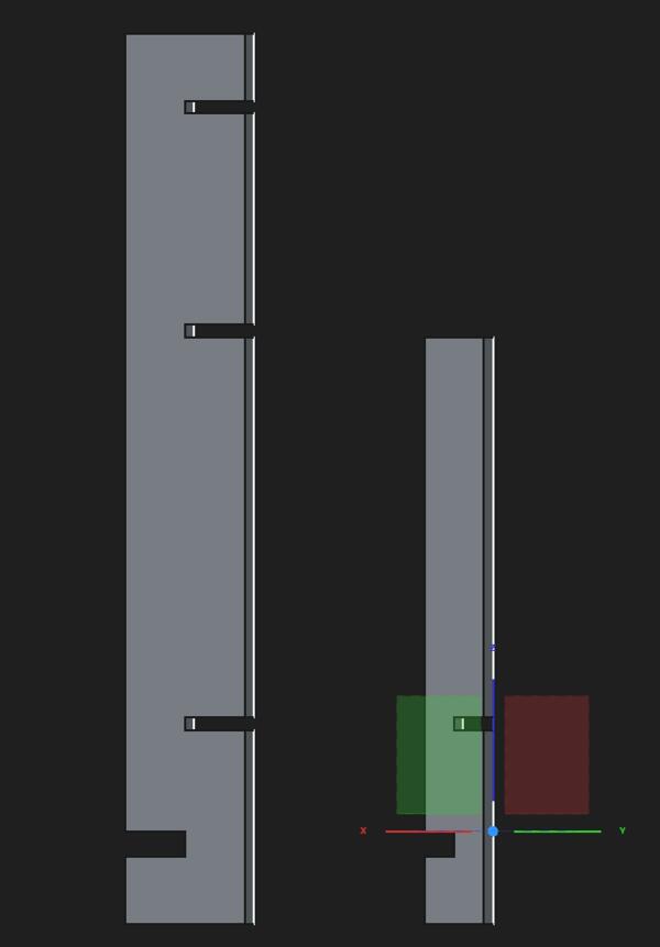
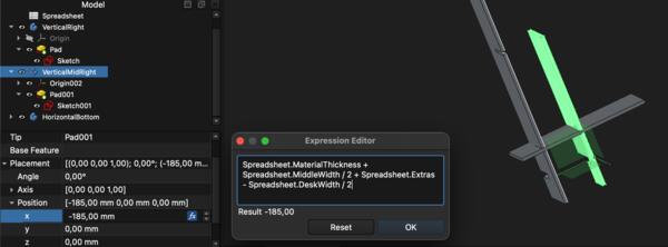
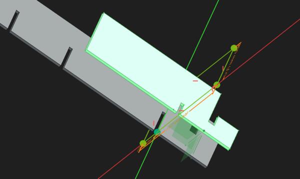
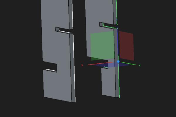
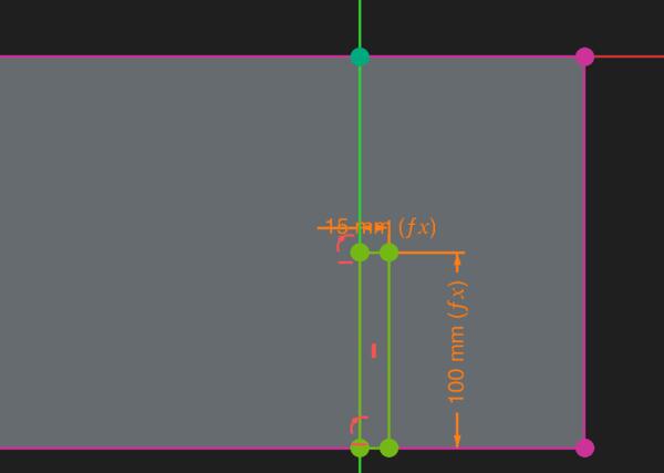
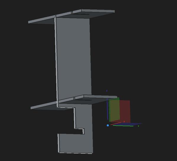
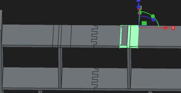
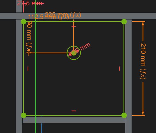
I fix the location for the horizontal piece (Z=120) and for the vertical middle right piece as shown in the image.
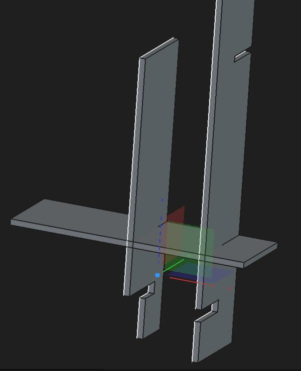
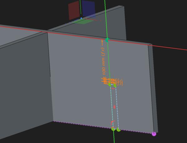
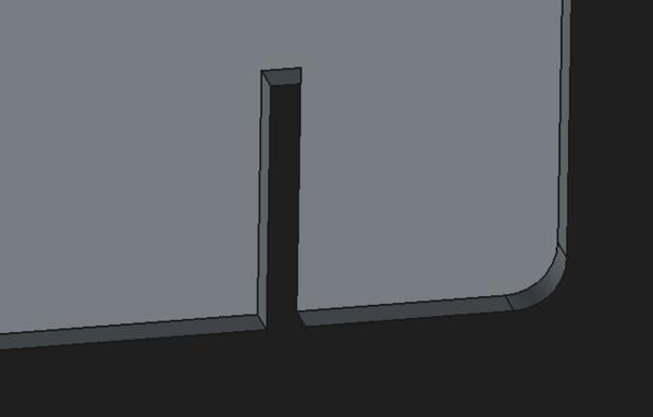
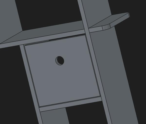
As I begin to make holes for the horizontal piece I realize that the hole in the vertical mid right piece was too short, so I make it longer.
Then I make the hole to the horizontal piece using external geometry, defining the dimensions for it and then in part design workbench I use External Projection tool to make a pocket. I select the side and make a sketch on it. With External Projection I select one edge. Then I draw a rectangle and constrained it. However, I wasn’t able to do a pocket based on that sketch, no matter how I tried it; the pocket area never become visible.
I ended up doing the holes in the way that I knew: I made another body, and in it another sketch, based on that make another pad, and used that in Part workbench to cut the piece with a boolean cut.
I did the same for the second hole, but now I did faster by copy-pasting the VerticalRight piece and used that for boolean cut.
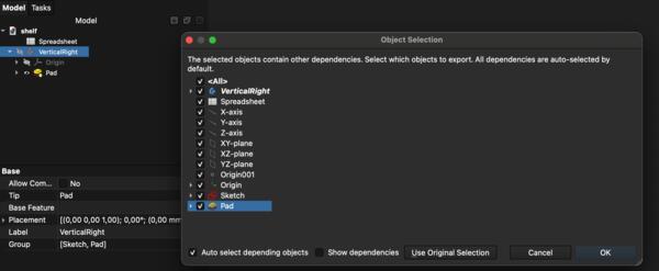
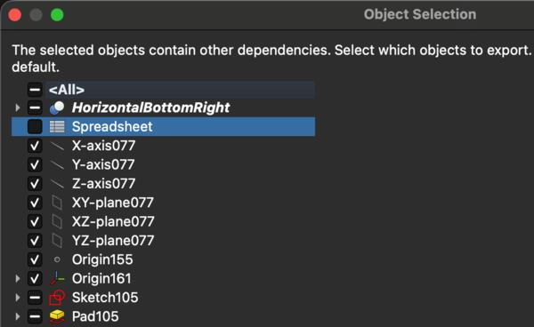
But then I went back with Cmd + Z and took a copy also of the horizontal piece before that cut because it will be usable for the upper horizontal piece. Doing copy-pastes, I need to remember to deselect spreadsheet from the copy list to have only on spreadsheet to refer to.
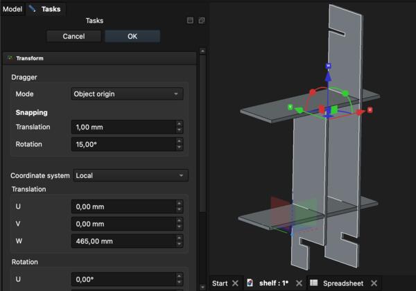
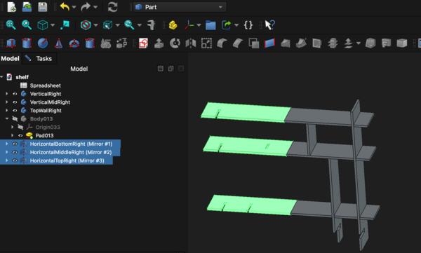
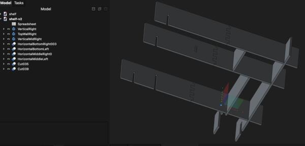
I right-clicked the horizontal piece copy, HorizontalTopRight, and transformed it up on Z-axis by the parameter MiddleHeight (450mm) + MaterialThickness (15mm).
But then I come to think that I maybe should have made the finger joints before copy-pasting for not to make them twice. Or I could make them using the same boolean operation process as with the holes and just copy-paste the cut-part. That is not too difficult to repeat a couple of times. I make one more copy of a horizontal piece and transformed it up by Top floor height (250mm) + MaterialThickness (15mm)
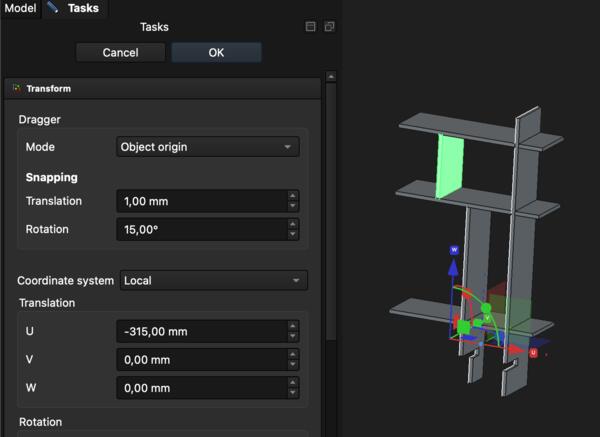
Now I make vertical wall between middle and top horizontal pieces. I want there to be two of those symmetrically and I calculated the distance from the vertical right to be approximately 315mm. I create a new body and new sketch within it. Create a rectangle, make a pad out of it and transform along X-axis by -315mm (and then -15mm more to add its thickness).
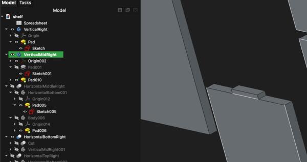
Then I do the pads for the two middle vertical pieces so that they lock into the horizontal pieces. I click the top side of middle right vertical piece and click a new sketch and it automatically levels with the selected side. I want there to be one pad/hole in the middle for locking the pieces together. I tried again the external geometry tool and selected the lines and made a rectangle between them. Then I made two construction lines to the sides and made all of the three equal.
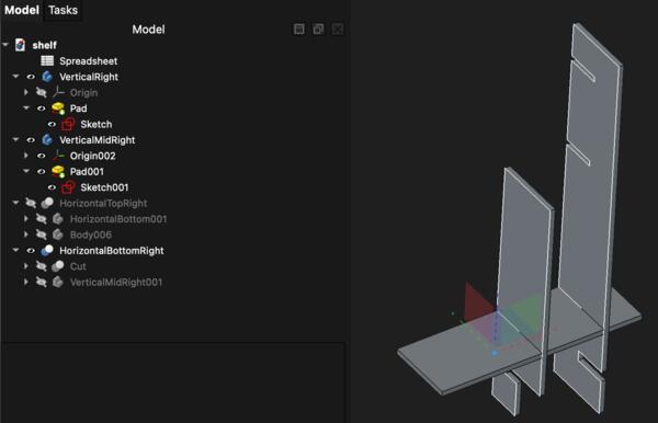
Then I made a pad ouf it and now I have two pads inside the VerticalMidRight body: the original without the newly made pad and a new one with the newly made pad as part of it.
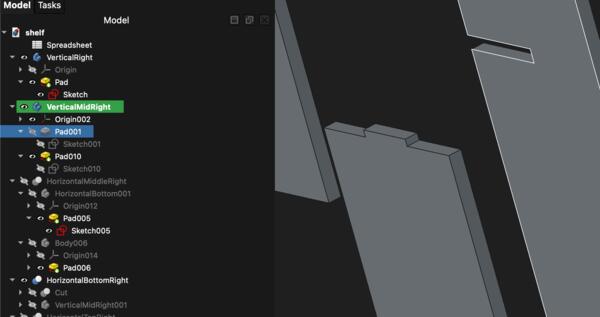
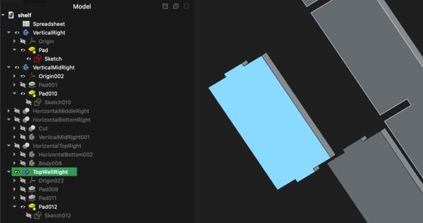
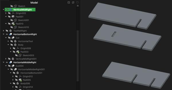
I did the same for both ends of the TopWall and then they looked like this.
Now I make clones of them and use them to cut corresponding hole to the horizontal piece. I do it on the Part workbench. (The long pad on the right was used before to make holes to the horizontal pieces)
Then I continue to make the finger joints to the ends of the horizontal pieces. In a new body, I sketch an appropriate shape, make it 1000mm pad, and transform it -515mm along the X-axis.
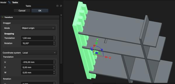
But now looking at that, I don’t actually want those cuts to be on the left side pieces, so I need to mirror the right side pieces before making the finger joints. I selected all the horizontal pieces and in Part workbench I used Mirror tool to mirror them in YZ-plane. Then I selected them all and with Right Click > Placement I was able to move them all -970mm on X-axis. There is, however, now the problem that the original right side bodies are now part of the original mirrored bodies. So I make clones of the originals and mirror those.
I found a mistake in the HorizontalMidRight piece: I wanted the bottom to be free for my loud speaker but now the vertical structure was too deep. I had earlier fixed it wrong: the plywood that is under the desk is shorter instead of the plywood that is right on top of the desk.
The mistaken piece:
The corrected piece:
I had to lift up the horizontal pieces by 10mm, and while doing that, I noticed that I had made errors with the boolean cuts earlier: the pads have gone all the way through the horizontal pieces and the vertical pieces had also chopped some material out of them.
I had to make them from the start. Perhaps there could have been another way but I couldn’t find the pre-cut bodies in the tree view so I decided making new ones is faster. I just made clones of the vertical pieces and In Part workbench made the boolean cuts. That didn’t come as easy as FreeCad didn’t just want make booelan cuts so I made new pads from sketches for all of the horizontal pieces and make new cuts. Then I had many unnecessary bodies which I had to delete and that wasn’t so easy as they seemed to have some interrelations with the previously used clones. Anyway, now the structure looks like this and I hope there’s nothing broken inside those bodies (there wasn't).
I had accidentally removed the body that I had made for the finger joints so I do that again as well.
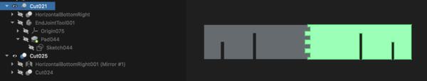
Then I made a mirror body of the bottom horizontal piece and made a boolean cut with the end joint helper body. Then with that I did a boolean cut with the mirror body. I always took a copy of body that was used for cutting. I was confused at first that the cut didn’t work but that was because the mirror body had still the original copy visible and in place, looking like the cut didn’t happen. But when I hid the copy, the result looked like this:
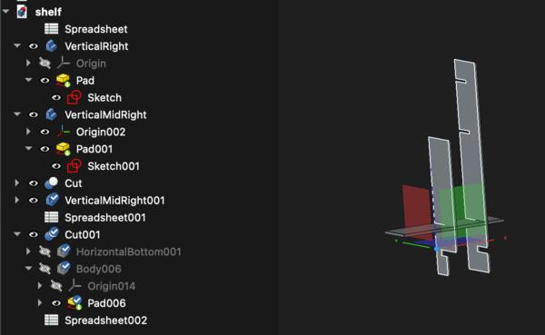
And as I had almost done all the mirroring, FreeCad crashed, shut down abruptly, and didn’t recover anything when reopened! I hadn’t saved the work in over four hours. Fuck this. The saved file looks like this:
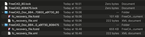
I tried figuring out the recovery with Gemini but that didn’t help. Before quitting the whole thing, I went to FreeCad preferences to toggle recovery data and auto saving options and found cache folder in General > Cache. There I had my recovery files. I moved the largest file (655kb of work) to my project folder, renamed it, opened it in FreeCad and IT WORKED.
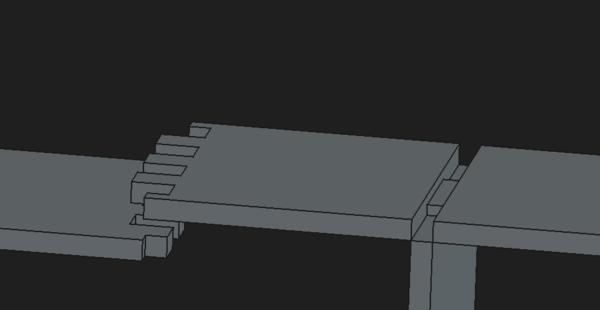
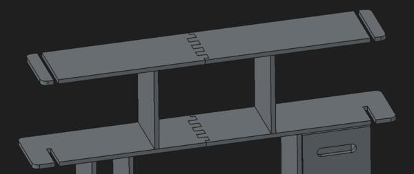
I continued with mirroring the top horizontal pieces and cutting the finger joints in them. Now the thing looked like this:
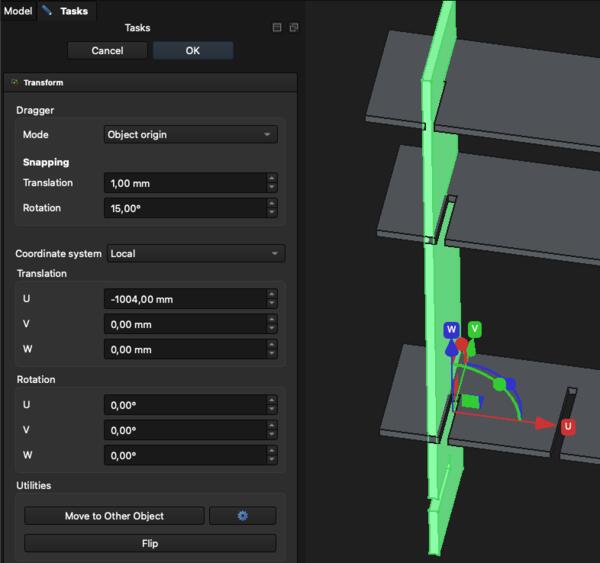
Now I start copy-pasting the vertical parts and locating them in their right places on the left. Transforming the copy of the right most vertical body -1000m on X-axis, I found out that the holes were not in their right place. It looks like the top left horizontal piece is too long.
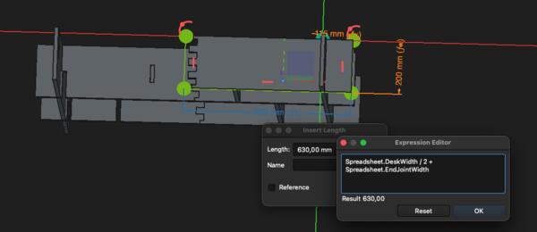
The problem was in the sketch that I had recently made: the top part should have been Spreadsheet.EndJointWidth divided by two, i.e. 615mm wide but now it was 630mm. Just fixing the sketch does nothing for the few times cut body.
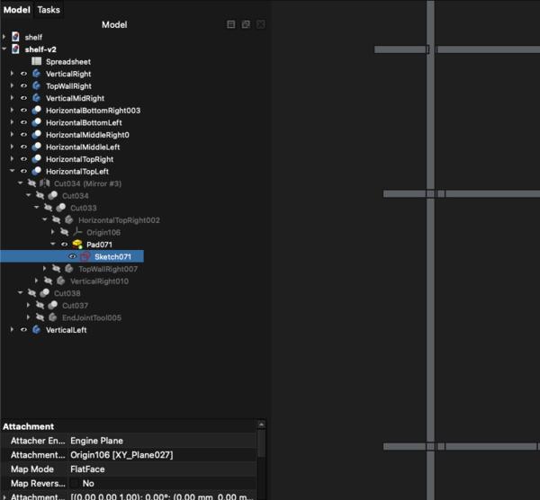
I ended up deleting the mirrored one and copy-pasting the previously cut version from the treeview: it had all the cuts except the latest, the finger joints. For making the finger joints … FreeCad crashed again but now the recovery worked and I started a few steps behind where I still had the EndJointTool available so I used that to make the fingerjoints. Then I finished the left horizontal part and took clones from the vertical bodies and transformed in their place. Now it looks like this.
Now looking at the front, the extras on the side seem to be too wide and the side sections are a quite narrow, so actually I would like to move the side vertical a bit more towards the sides. That would require moving the holes in the horizontal bodies.
Sides too wide:
Sides shortened, side compartments widened, and also new holes were made to the horizontal pieces:
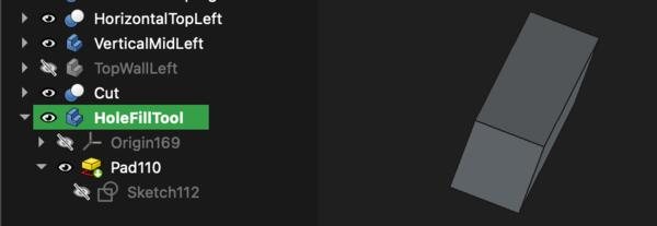
To fill the existing holes, I made a hole fill tool.
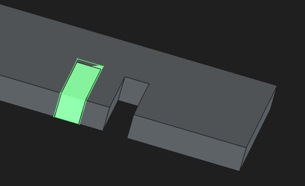
I ended up using this once and then realized that I can find from treeview the bodies that don’t yet have those holes and work with them. So I just worked with copies and boolean operations in the Part workbench and in about half an hour all the holes were changed.
Now I also want to make the top area a bit higher so I also move the holes in the side vertical pieces and make the inner walls 30mm higher. Thanks to parametric design in this regard, I only changed top floor height from 250 to 280 and and the changes in pieces were done.

Then I needed move the horizontal pieces 30mm up the Z-axis. But when I had done that, the cut in the horizontal piece turned out to be faulty.
I went back with Cmd + Z and lifted the horizontal pieces before updating the top floor height on the spreadsheet. But the cuts didn’t disappear even though I didn’t see them in there before doing the changes. I will just make new body with which I use to boolean union fill those gaps.
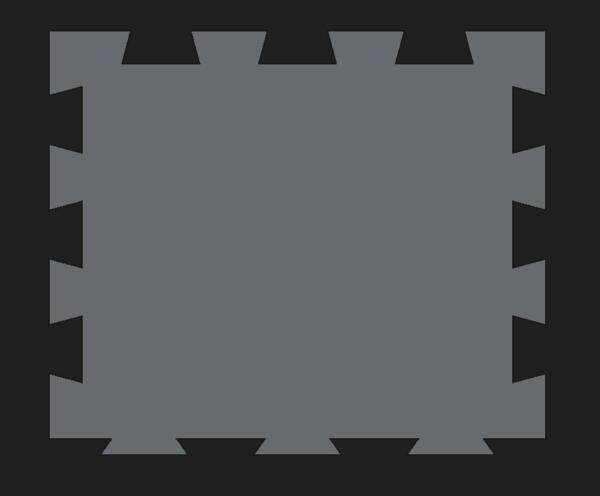
I also changed the Extras parameter from 100 to 70 to have the top of the side verticals to come down the amount that to top horizontals went up. And I widened the horizontal pieces to come a little further to the sides from the side vertical. I can for example keep my drinking glass there and not accidentally spill it on the desk. I’ve figured out that if you want to find the original sketch to edit, you need to click open all the top bodies/pads in the tree view.
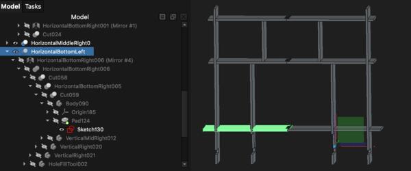
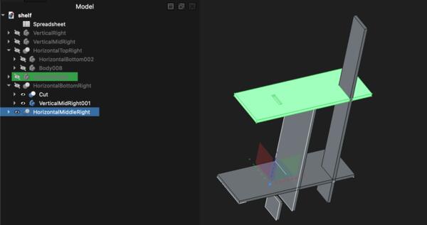
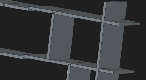
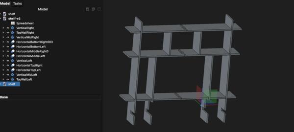
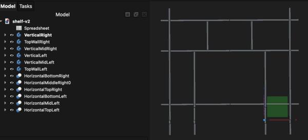
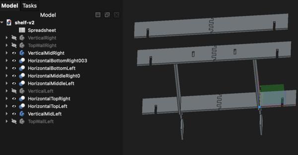
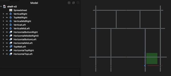
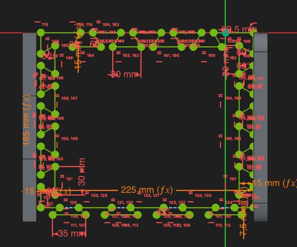
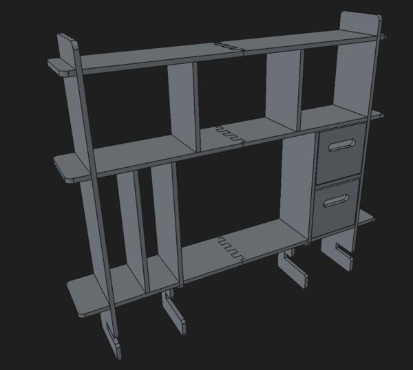
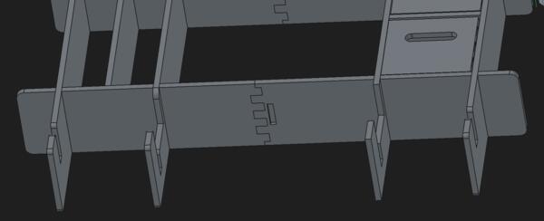
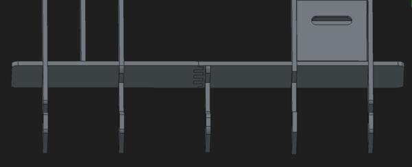
After adjusting the horizontal side lengths, the shelf looked like this.
Now, I want to divide the side compartments in the middle. To the left I make vertical wall and to the right a horizontal floor. Starting from left, I create new body and a sketch on YZ-plane. After finished sketching, I take a copy of the new body, select the horizontal piece and then select the copy and make a boolean cut. This shown in video below and is basically how I have done the cuts this far. Using clones instead of copies often raise problems that I don’t yet understand.
Then I do the same for the right side, except I make a horizontal piece.
Then I begin finishing by making fillets to the corners. Now my problem is that I cannot select active body by right clicking it, the selection is not visible, and I don’t know how to select the active body. After a while I figure out that the problem seems to be that some of these parts are not shown as bodies but boolean cuts, and the latter cannot be selected as active bodies. By testing I found a way to overcome this: I select the boolean cut and click New body. This creates a new body that has the boolean cut as BaseFeature and then I can select it as an active body and make fillets normally.
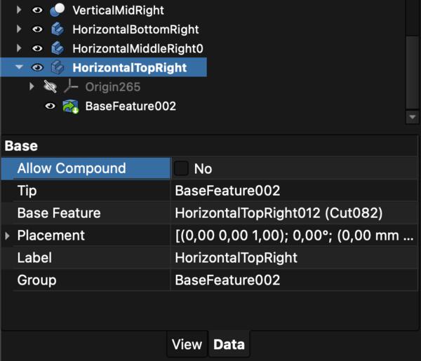
But for the HorizontalTopRight piece FreeCad couldn’t make the fillet but demanded that “active compounding” is allowed.
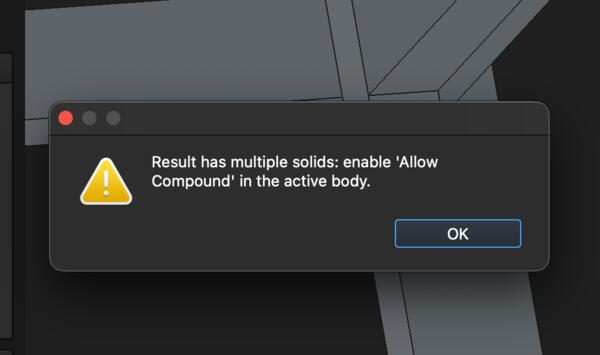
This is because the body was made of compounds that were the result of boolean cuts in Part workbench. I was able to allow active compounding on the data tab of that body.
Continuing that, it soon has fillets everywhere needed, I feeling quite satisfied with it.
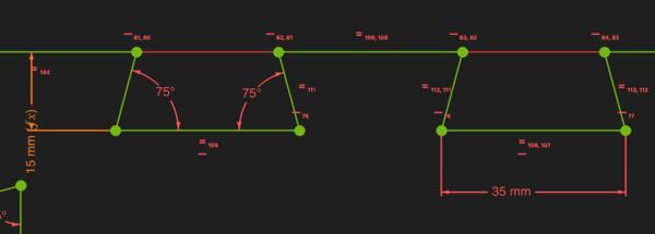
I will make containers to the right side middle compartments and for them I’ll use dovetail joints. I begin with the front piece. I create new body, sketch and make it a pad. Then I decide to do the hole slightly differently as below
Sketching the dovetail took some time and as I had it done like below.
Then I thought that maybe there is too many of those joints, so I removed one on each side.
Actually the problem seems to be the angles of the joints that make them so narrow where they are attached to the bottom. So I changed the angles from 60 to 75 and narrowed them by 5mm.
Then I made the sides of which the other one is a copy of the other.
Then I made copies as necessary to cut the joints with Boolean cut in Part workbench (as usual). When done, the box looked like this.
Then I copied and pasted all the five parts and moved the second box to its place.
Moving on, I actually come to think whether the middle area is well enough supported to carry the weight of my screen, as there’s only 20mm supports on the mid verticals and the holes are smaller on the mid vertical piece.
I decide to make a couple of support legs. I make a new body and sketch following the mid vertical piece.
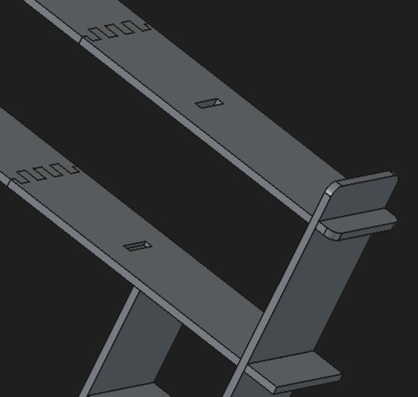
As I had made the supports, I noticed that the middle joints of the horizontal pieces are not in the middle, and I wonder why is that and whether I should do something about it. The mistake was done as shown in the image: the EndJointWidth is added to the width although only half of the end joint width is increasing the width, because the whole width was supposed to get shared by both pieces.
I’ll leave it like that and now I can use only one support that can be place in the middle of the shelf without intefering the finger joints.
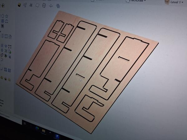
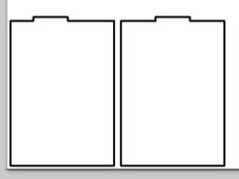
Now let’s see if all the pieces fit to the piece of plywood provivded by the lab. Some of the “bodies” are not bodies as such but boolean compounds and I don’t if that affects the process of making the pieces ready to be cut. I go to TechDraw workbench and create New page. In the Data tab I can see the folder where the template is.
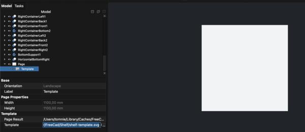
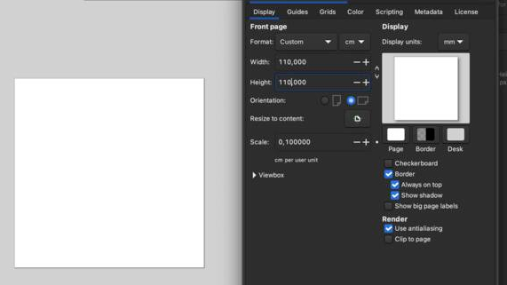
To have a template of an exact size, I go to Inkscape, create a new file, at File > Document properties I set the dimensions to 110cm x 110cm, and then save the file. In FreeCad Data tab (click Template folder path and … on the right) I define the template folder to be the same where I saved the svg from Inkscape. Then I have the template in FreeCad.
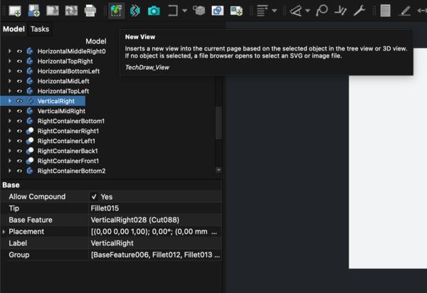
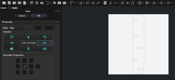
In Techdraw workbench, I select a body and click New view. The piece loads there in wrong way but pressing arrow to the side, I can turn it right.

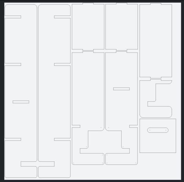
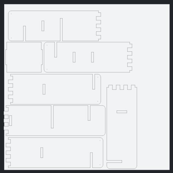
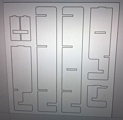
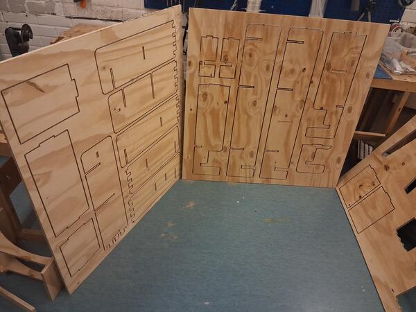
Now I can already see that one plywood won’t suffice at all. I was able to fit all the vertical pieces (except the containers) on one 1100mm*1100mm plywood.
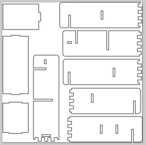
Then I made another page and template which I set to be the template svg from Inkscape. I placed the rest of the pieces on that. There are pieces which have pockets on both sides which require turning them after milling the first side. However, one piece was looking like this and it’s the same on the other side.
I made another body which I used to fill the spot and now I had all the horizontal pieces on another plywood.
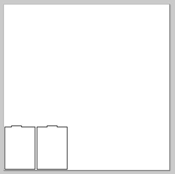
While placing the items on the template, I realized that not all the container pieces can be milled in 2D because of the dovetail joints. Take for example the front piece: the dovetails are widening inside the piece, that’s not propably feasible even in 3D, but they should be milled from the side. The back piece has the slopes in the dovetails that requires 3D approach. So I quess I leave the containers out for now at least because I'm not up to redesigning them.
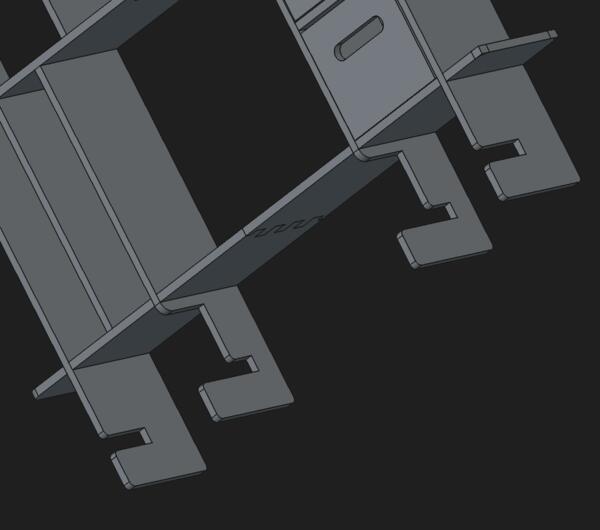
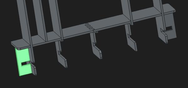
I added these side supports to have the shelf "locked" to the table also from the sides.
Then I made through holes of the top horizontals to hold the small vertical walls as the middle horisontals are being carved only from the other side and turning them around is a hassle I want to avoid at this point. (In the milling phase I forgot that these were through holes and they became pocket anyways.)
Exporting the model for milling
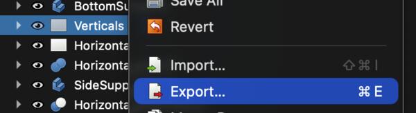
On FreeCAD I select Export and choose Technical Drawing.

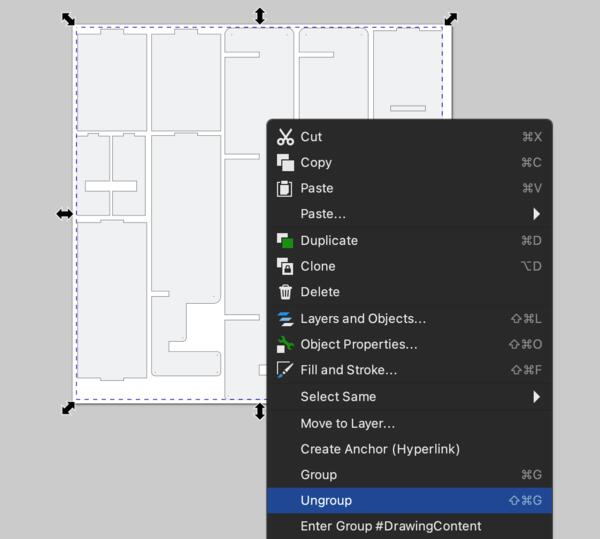
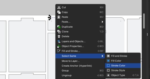
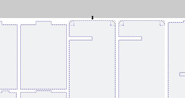
Then I opened the exported svg-file on Inkscape. I removed the strokes as they were single lines instead of contours by clicking one line, righ-click it > Select same > Stroke color and Del.

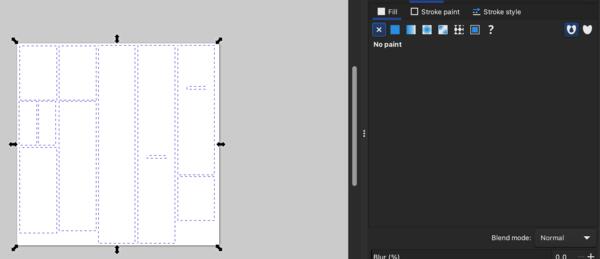
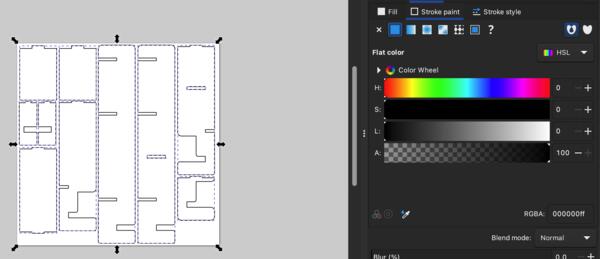
Then I also removed the fills and added new strokes.
At the day of milling, I was first noted that the pieces were placed too close to each other so I had to reorganize them. From the first svg I deleted some pieces at the CNC-computer before starting the milling. Then all of the pieces didn't fit in two plywoods anymore.
CNC milling
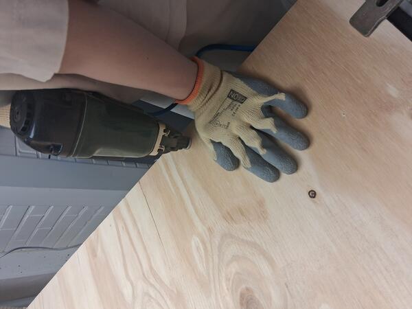
The actual milling process we (me and lab assistant) started clamping the plywood on the platform, then shooting composite nail two/three per side. .
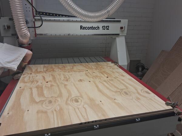
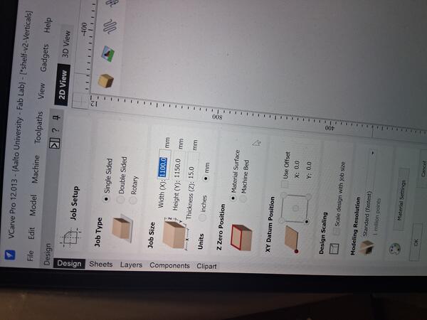
Then on the computer we started by setting the dimensions for the mill. The plywood was 120cm*120cm so we had a little margin, a bit more on clamp sides.
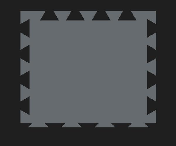
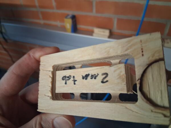
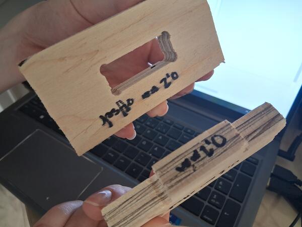
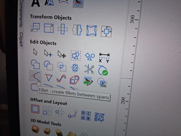
We added fillets to all corners that needed to fit in to other piece, because otherwise the tool leaves a round corner which won't accommodate corner too well, as shown in the test pieces at the lab.
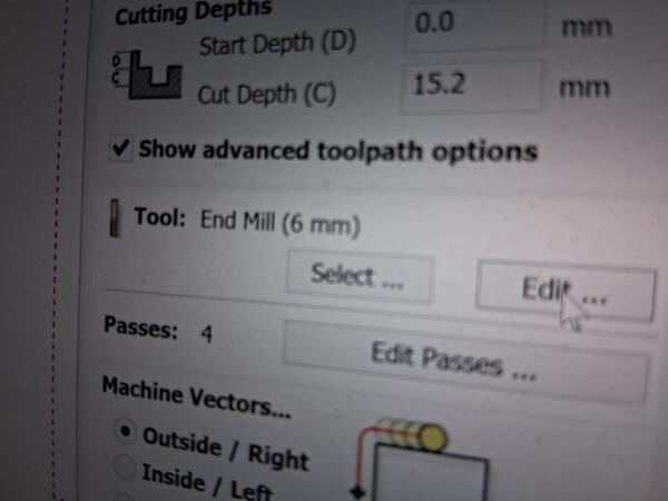
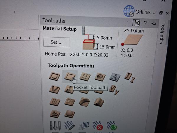
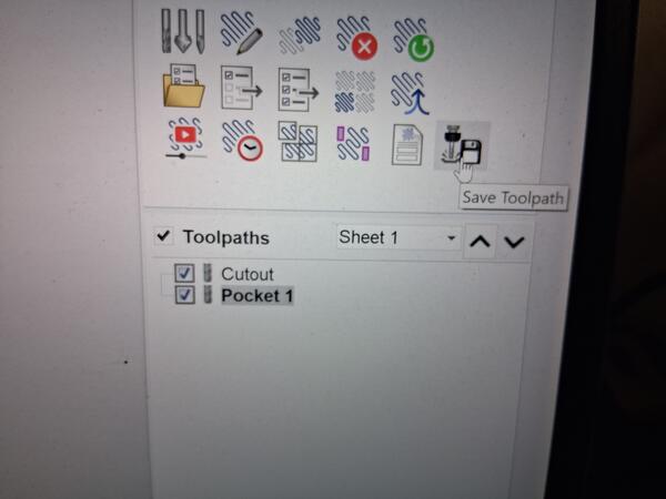
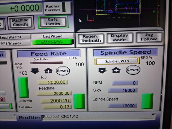
To set the toolpaths for cutting through the whole plywood, we pressed the first icon on the Toolpaths menu (on the right). To ensure that it really cuts through, we set extra 0.4mm to Cut Depth.
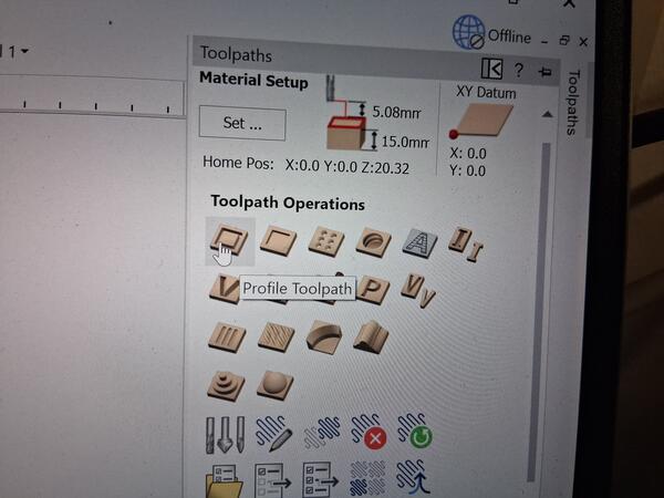
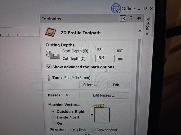
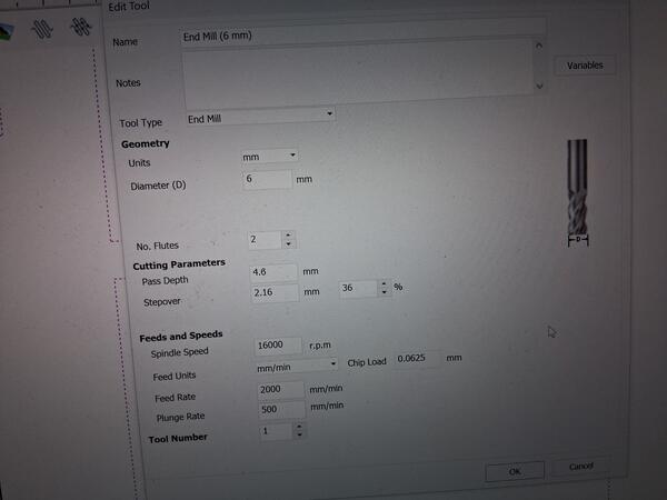
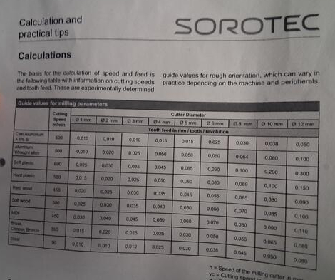
The right parameters for cutting plywood were already calculated in the advanced options, but if the material was changed, the correct values for further calculations can be checked from the machine instruction.
On the same toolpath, we added tabs so that the pieces stay intact while milling/cutting.
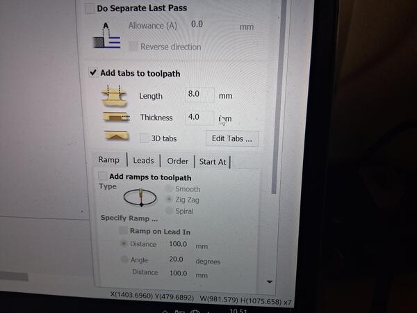
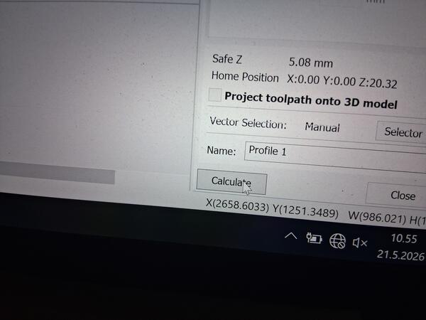
Then hit calculate at the bottom.
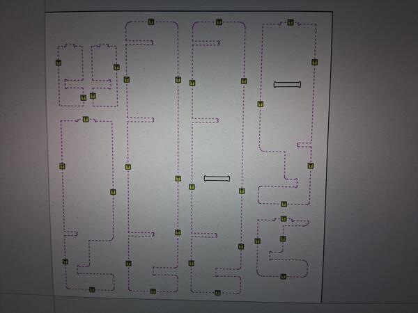
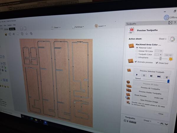
Clicking Preview Toolpaths shows a 3D model of the result on which can be checked that everything is as supposed to.
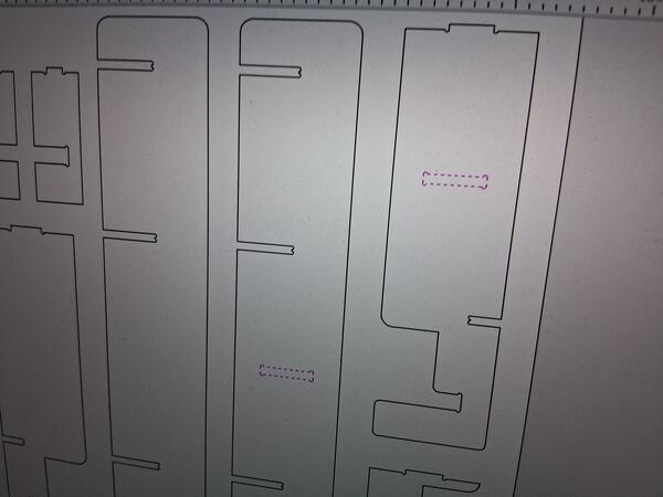
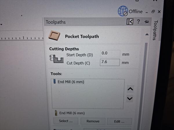
Behind the next Toolpaths icon we defined the pockets to be engraved. We set the depth 0.1mm deeper to ensure that the pieces really fit the pockets.
Then we saved the Toolpath(s) which creates a text file with G-Code in it.
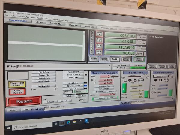
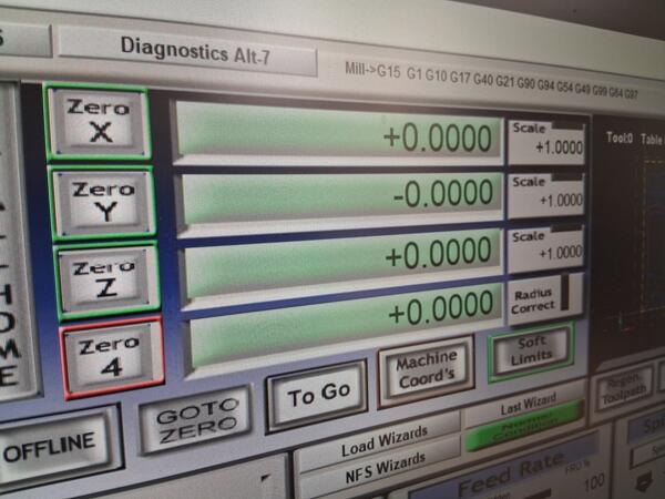
Next we opened the software for controlling the machine. On the dashboard we pressed Soft Limits on, REF ALL HOME, and then Reset
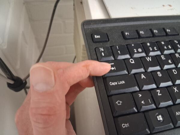
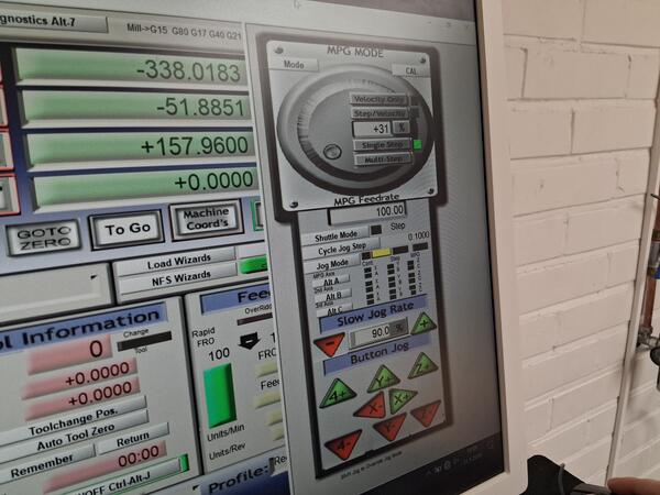
Pressing Tab opens the area where the tool can be moved with the arrows.
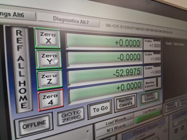
Then we set the XY origin by moving the tool to bottom left corner while leaving enough margin. Pressing Zero X and Zero Y on dashboard sets the origin to the spot the tool is positioned.
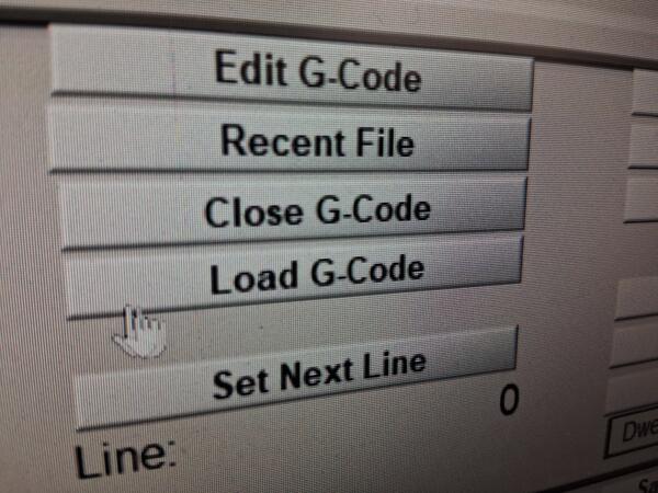
Then we loaded (the first) G-code file to the machine software.
We ran a safety run by having the Z-origin plenty above the plywood and checked that it stays withing the limits of the area, e.g. not hitting the clamps.
We stopped the run as we saw that everything was fine.
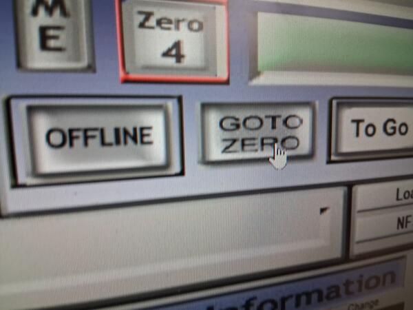
By clicking GOTO ZERO we hade the tool back the set origin.
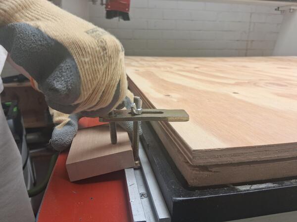
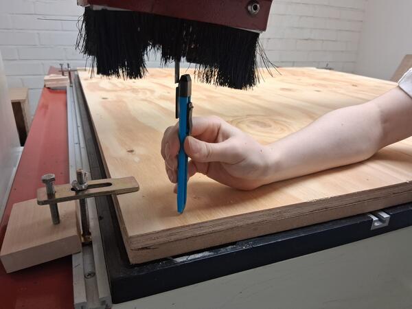
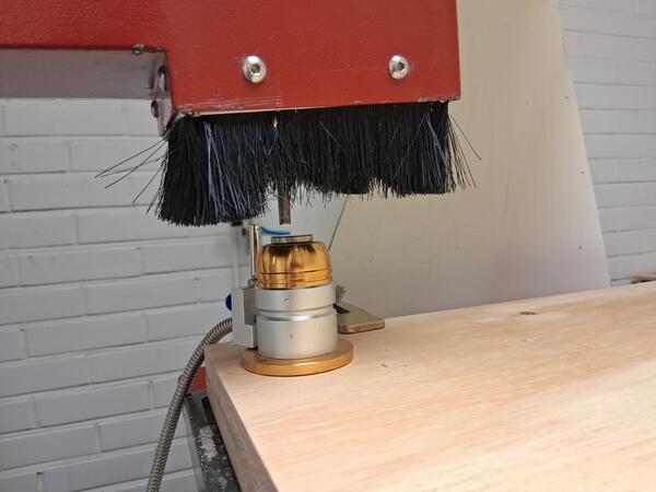
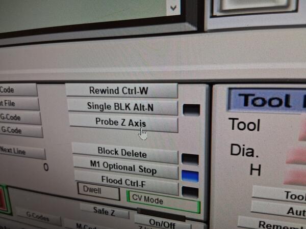
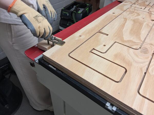
Then we began defining the actual Z-origin, which was done with a tool shown in the image.
Then we were ready to start the mill.
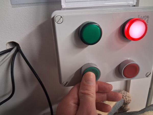
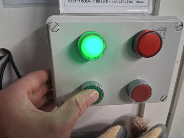
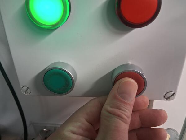
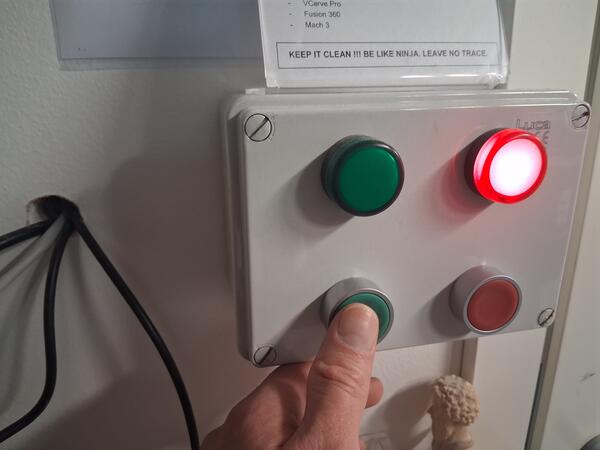
If the process needs to be paused, that can be done by first pressing the lower red button that stops the machine from moving, and then clicking Spindle CW F5 to stop the spindle. This ensures that the machine won't move the tool when the spindle is slowing down.
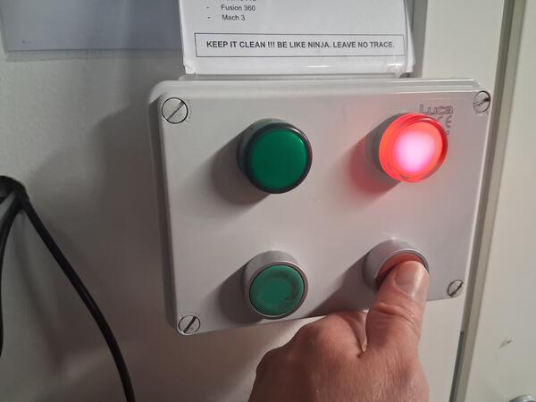
Then by pressing the greeen button again continues the process where left.
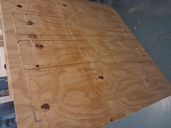
As the machine finished, we removed the clamps and removed the plywood with chisels out of the composite nails.
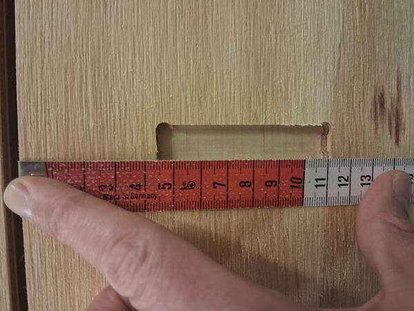
Soon I saw that on a top vertical piece, one pocket was slightly misplaced: I had moved one piece on Inkscape without selecting the pocket along with the piece.
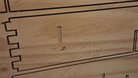
I measured the pocket's distance from the edge and updated the top vertical piece/inner wall.
I also noticed that some spots had not been cut through fully, but this was so thin that it was relatively easy to cut by hand.
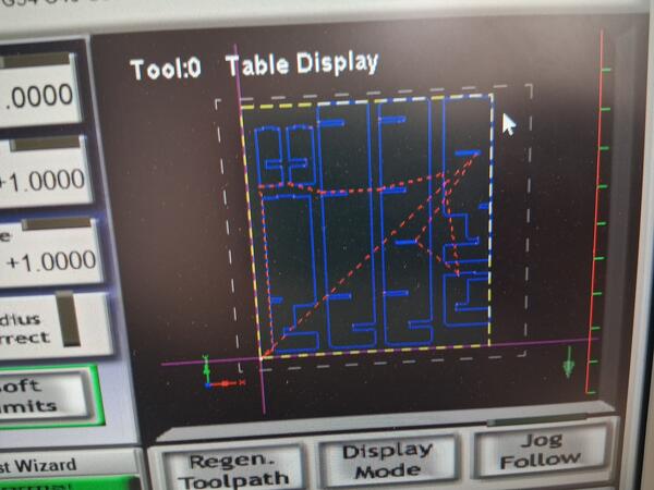
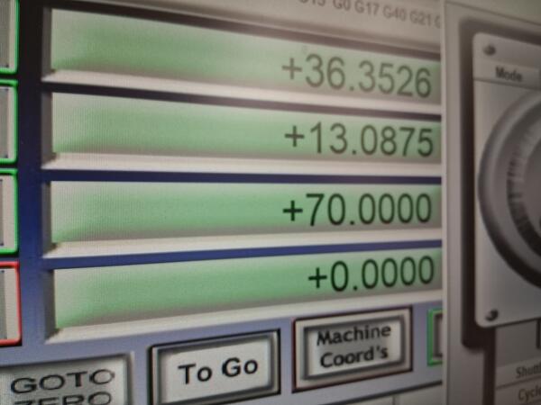
I set the cutting depth 1mm deeper and repeated the same process two times. Now I was making it alone as instructed before but asked help for two times. First was about the safety run as I didn't remember how that was done. The guy I asked did not about it but showed me another way: using the arrow keys to move the tool while watching the Table Display on top right corner as the tool is moved to each side of the display and then checking if it's within the borders of the plywood.
Apparently this wasn't accurate enough as I got an error saying something about soft limits and when I asked Kris, was exactly about that: I had set the XY-origin too up and the cutting would have crossed the top edge os the plywood. Thhis was fixed by setting also the height of the piece to 110cm as well as resetting the origin slightly lower.
Assembly
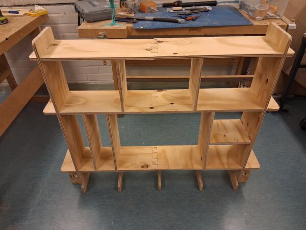
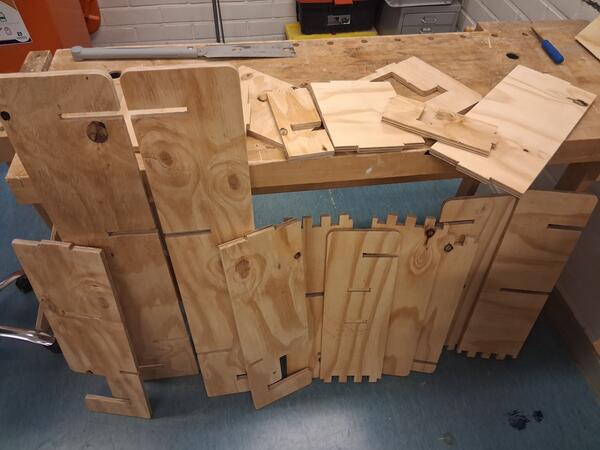
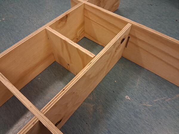
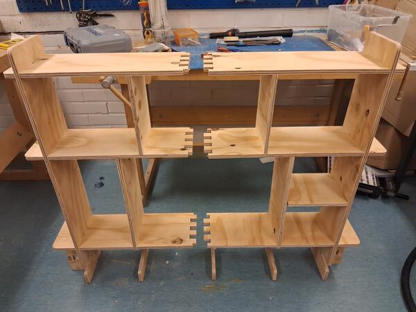
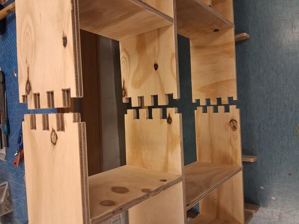
Then I managed to do the rest without problems and here are all the pieces:
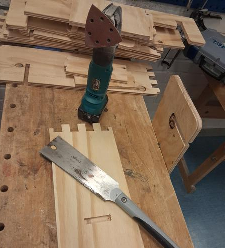
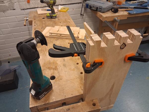
I used this saw to detach the pieces from the tabs and from the non-cut spots and the other powered tool to sandpaper the edges and surfaces.
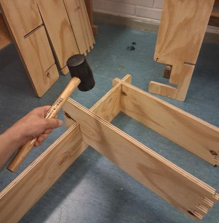
As all the pieces were done, I was ready to the assembly for which I used the soft hammer shown in the image. The fit with the crossings were excellent: tight but not too tight. After pushing them one time in place, I was able to push them in place by hand afterwards.
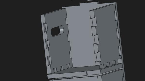
Then I found another mistake with a misplaced pocket while moving a piece in the svg. This is 1-2cm too far from the side and as a result the container rack didn't fit exactly on its place and the vertical piece is a bit awry.
I had engraved the pockets to the underside of bottom vertical but forgotten to update the top piece to match the missing pocket on the top side of the rack, so I had to saw off one piece from the vertical container wall.
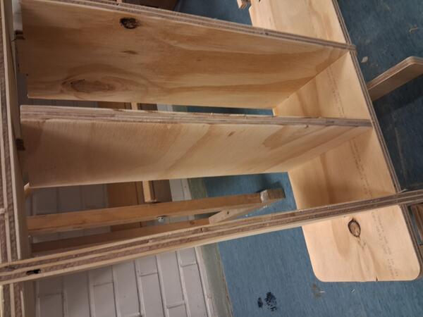
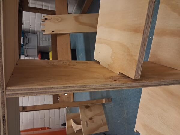
Now I had almost all the pieces in place (except the one above) but I found out that the fingerjoint do not fit within each other. There should have been a slight margin as now they were both excactly the same width (as they were done with boolean cuts).
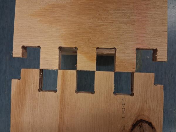
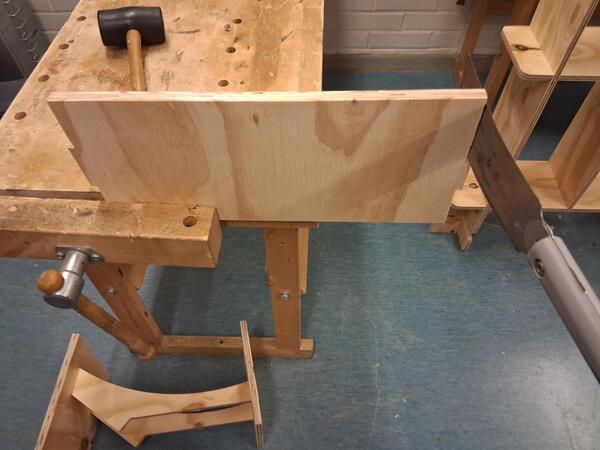
I clamped the three left-side horizontal pieces together and began testing ways to make them just slightly thinner but definitely not too thin as that would ruin the whole thing to some degree.
This tool didn't reach the bottom.
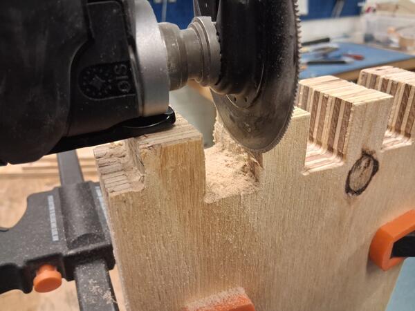
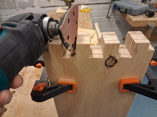
This tool wasn't as easy as I hoped for and it took about 15 min of sweating to finish the job. I used one piece from the right side to test when it was narrow enough.
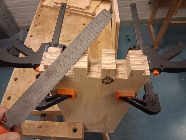
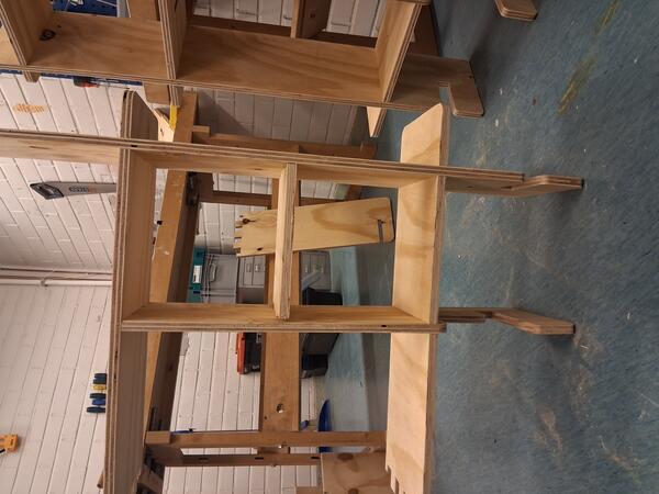
Now I was able to hammer the sides together. I'm pretty happy about the outcome: it's sturdy without any glue.
The final assembly takes about 5min and but here's a video of me assembling the thing again 10x faster (which I didn't do again only to have the camera a little better directed.)
I haven't yet tried to attach it to my table.
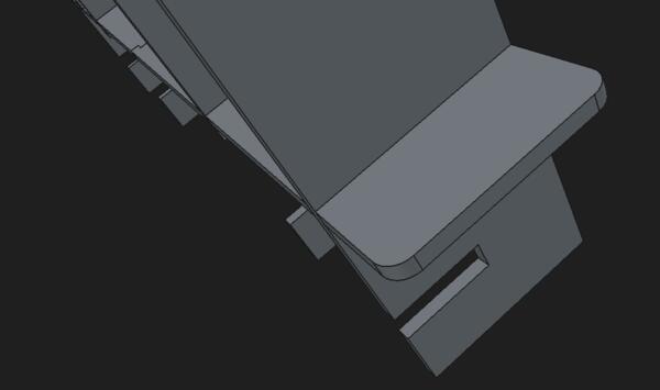
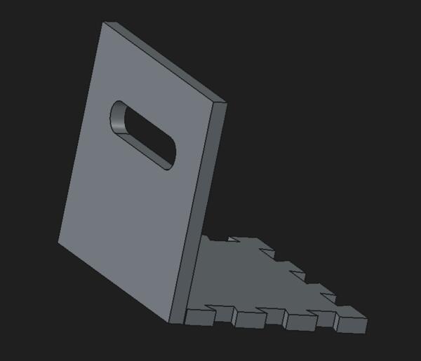
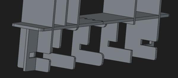
After trying to set the shelf up on the desk, I realized a critical problem in the design, which can be fixed, though, quite easily. The hole that the desk gets inserted were not aligned but the later adjustment made them have different depths. It was difficult to take a photo of the issue but it's somewhat visible in the 3D model: the insertion holes are deeper in the middle pieces than in the side pieces, where it extends further than half way of the piece.
This mistake would have been easily avoided if I had simply made a pad representing the table, which I, for some reason, found too burdensome and unnecessary. Now, as it's done, I need to saw a piece out of the side pieces to have them on the same depth that the middle pieces.