Production
For the production I use 3D Printing for the keys and housing of them, Milling for producing the PCBs and Laser cutting for creating the side and bottom panels of the keyboard.
PCB Milling
GCODE generation
For the PCB milling I again used mods.
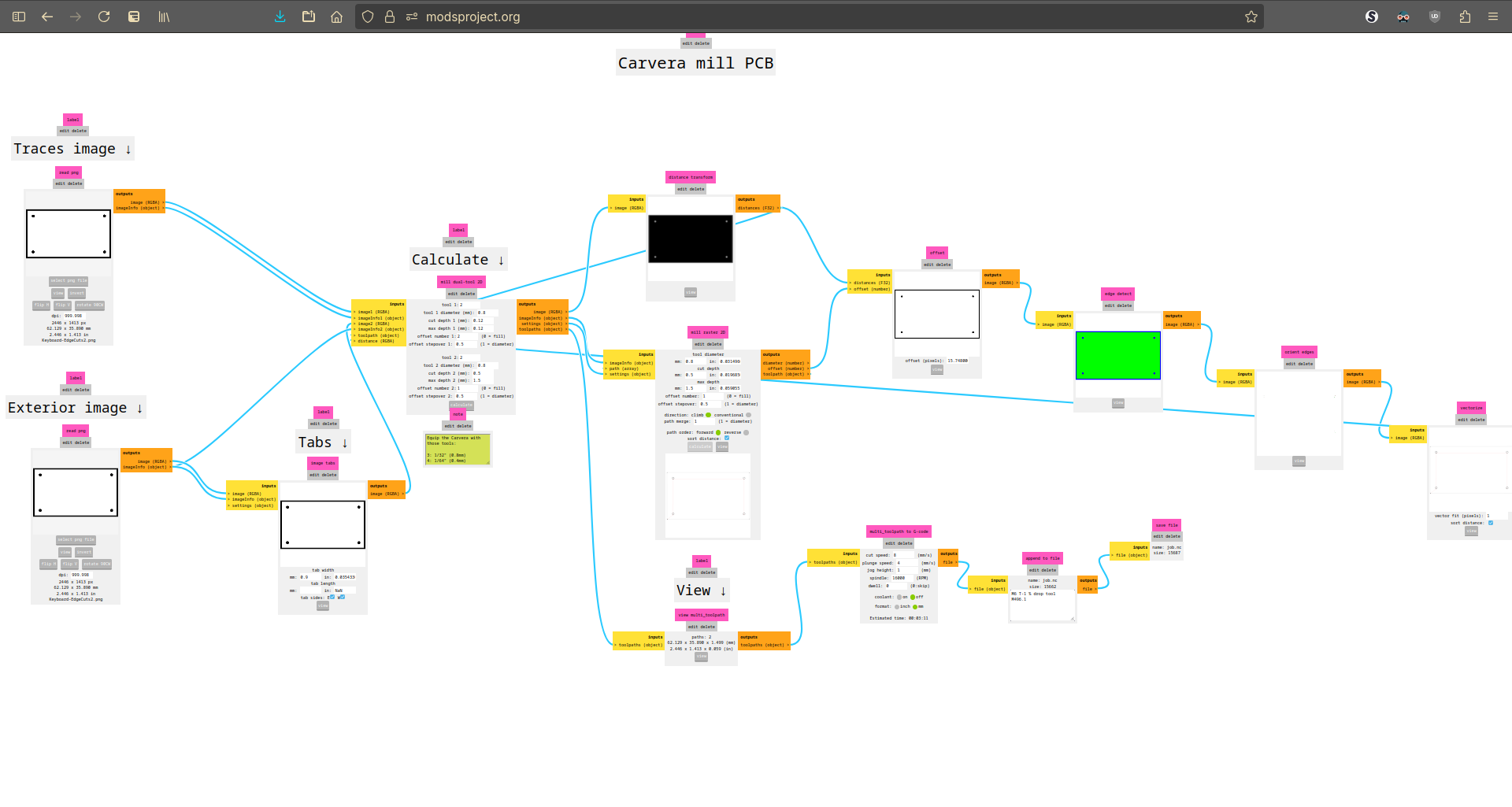
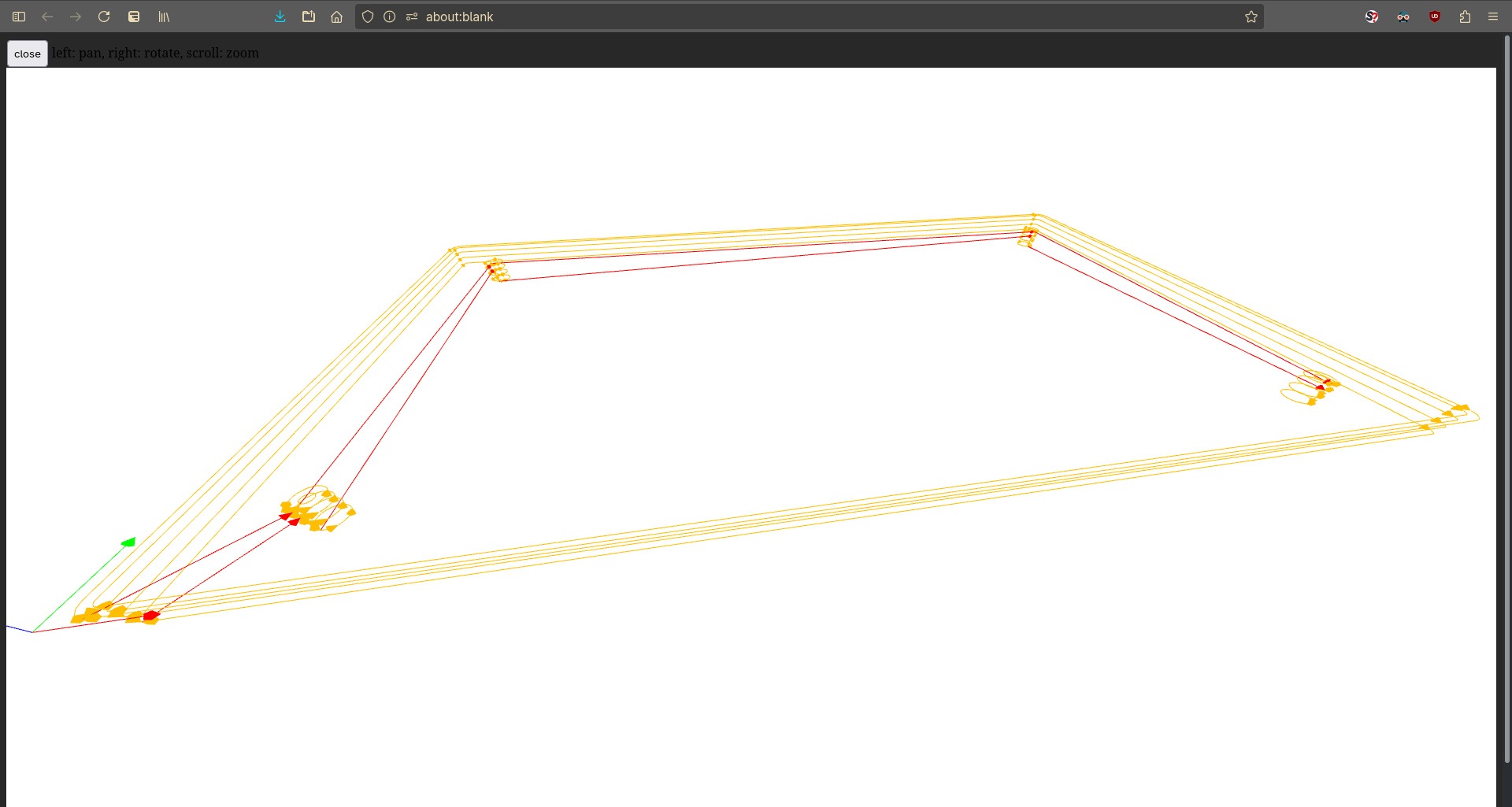
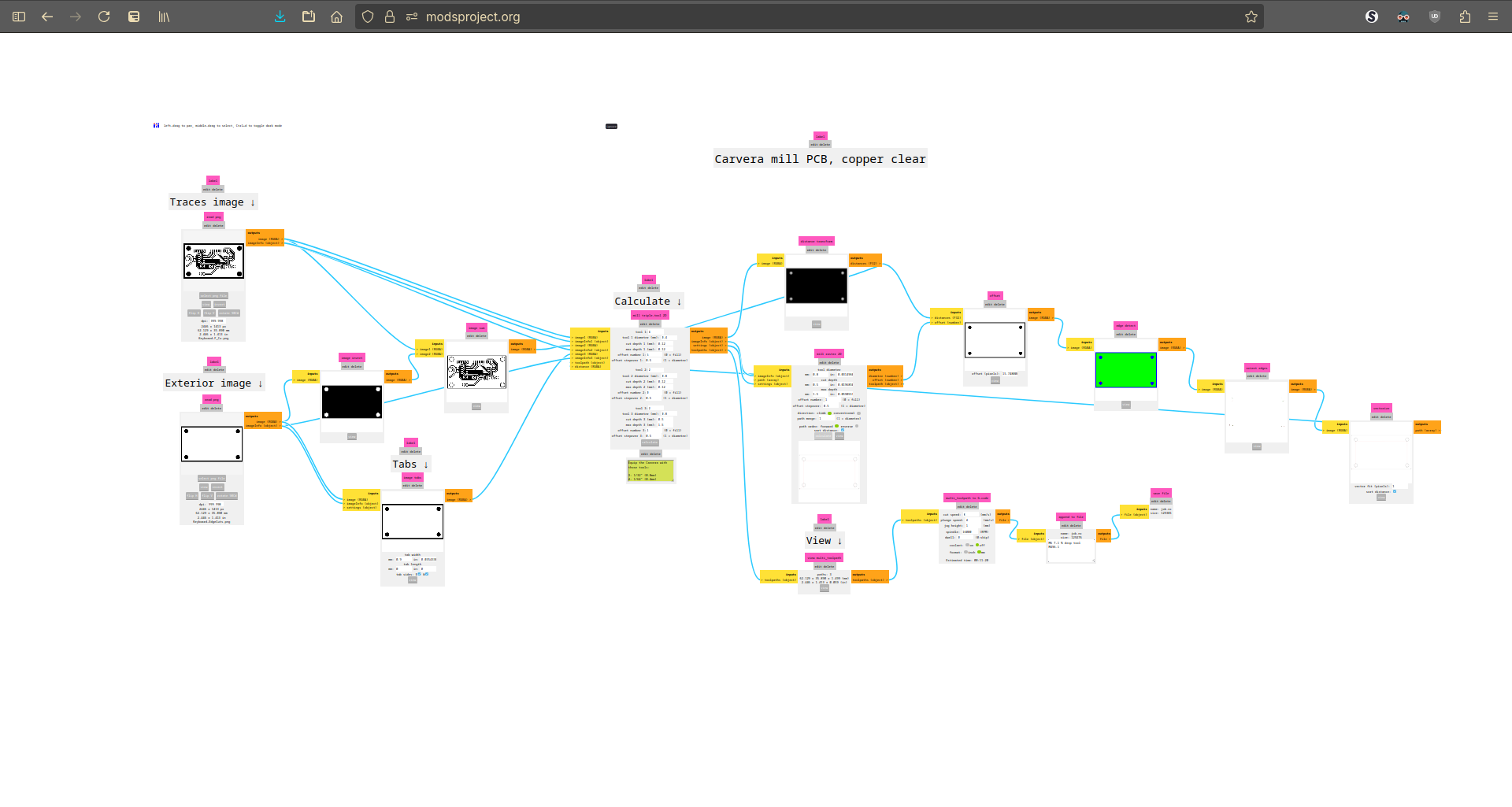
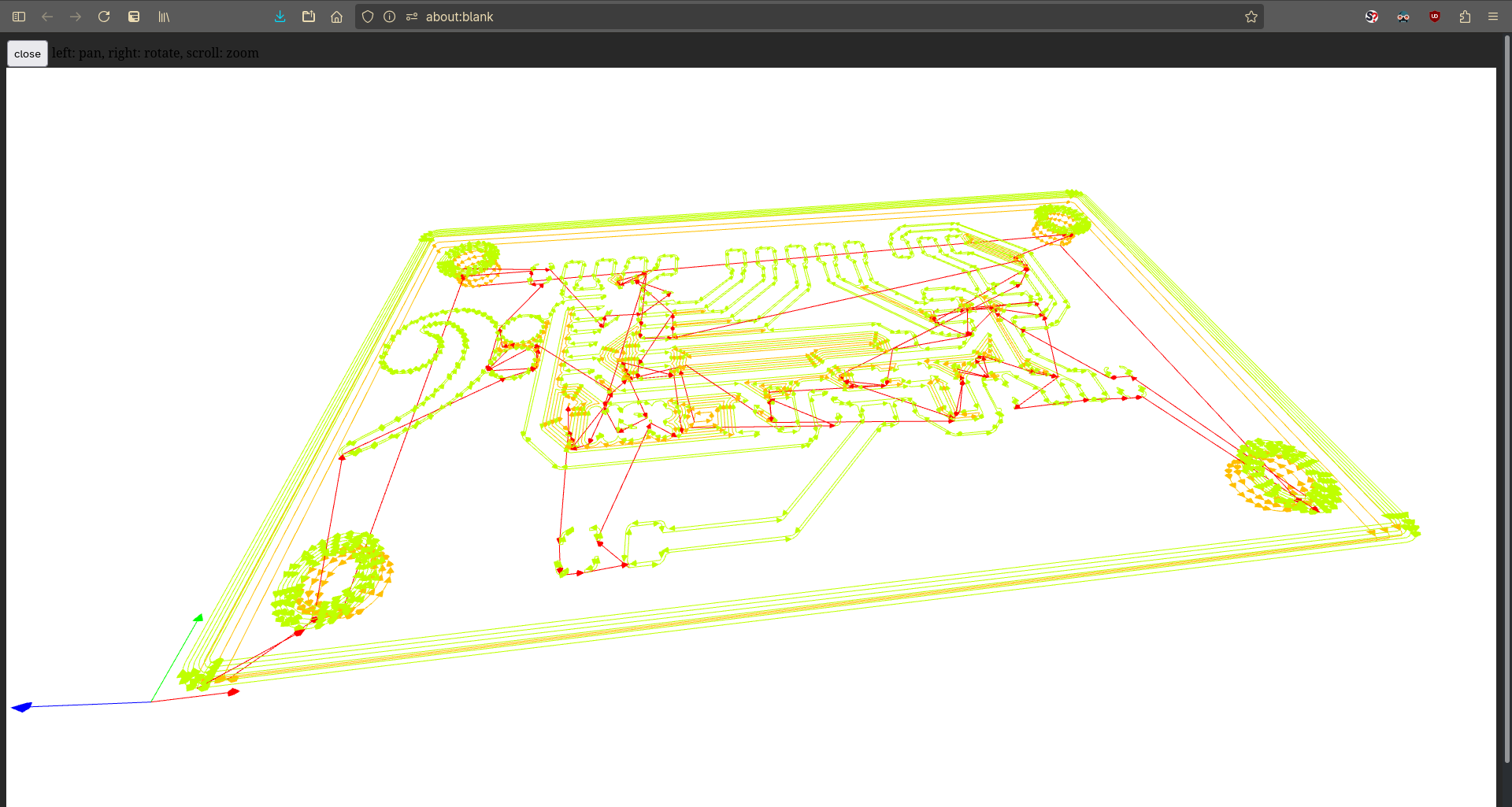
I always used following parameters ([mm]):
Process |
Bit |
Tool |
Cut Depth |
Max Depth |
Step Over |
Offset |
|---|---|---|---|---|---|---|
Carve traces |
Vbit 0.2 |
4 |
0.12 |
0.12 |
0.5 |
6 |
Mill away rest |
Flat Endmill 0.8 |
2 |
0.12 |
0.12 |
0.5 |
0 |
Mill out PCB |
Flat Endmill 0.8 |
2 |
0.4 |
1.5 |
0.5 |
1 |
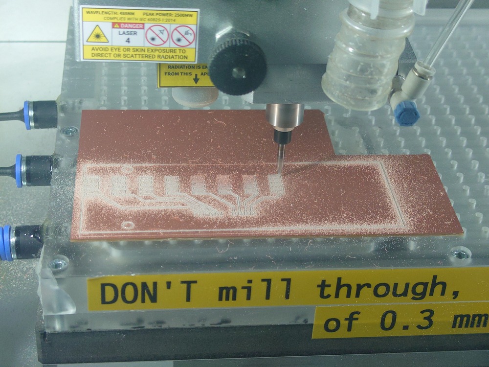
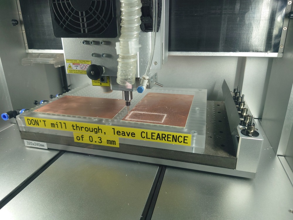
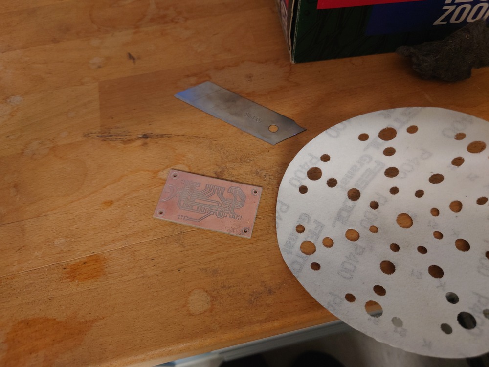
Milling
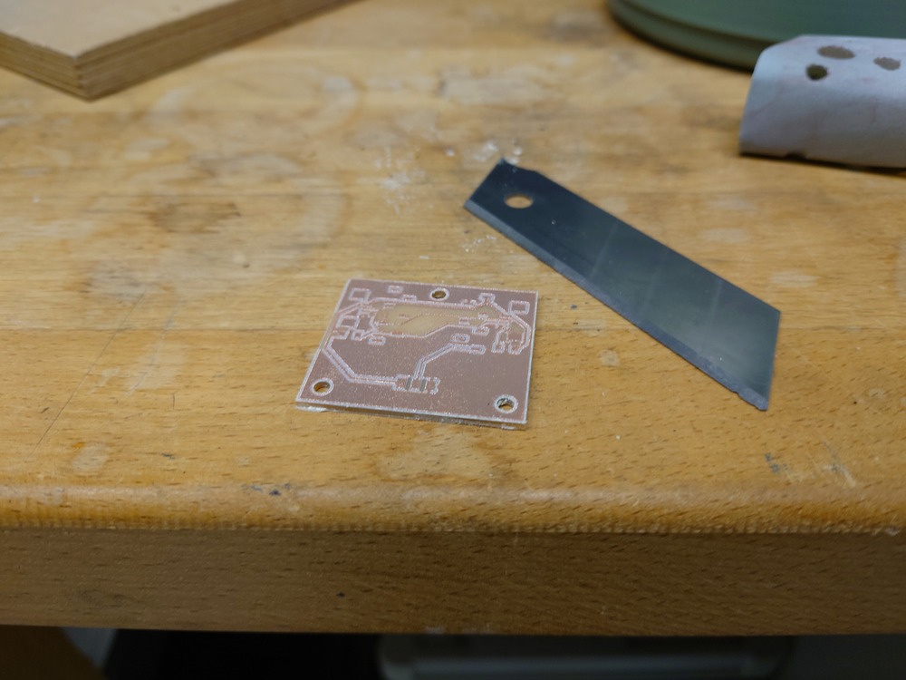
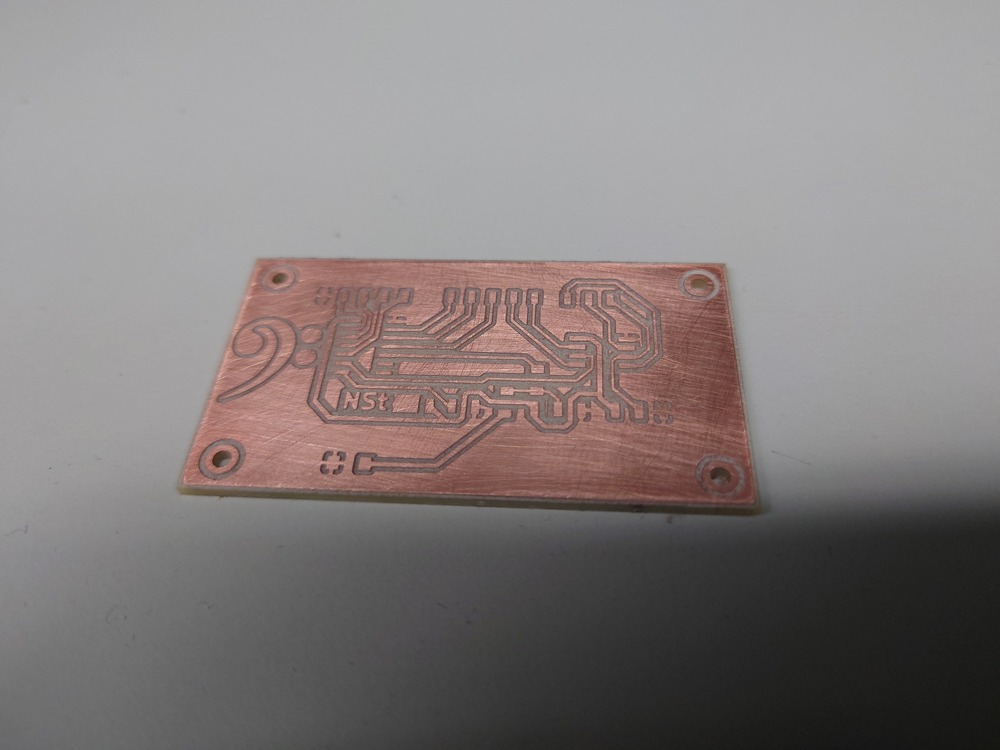
Post Process
Soldering
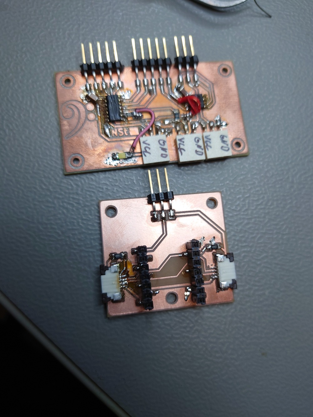
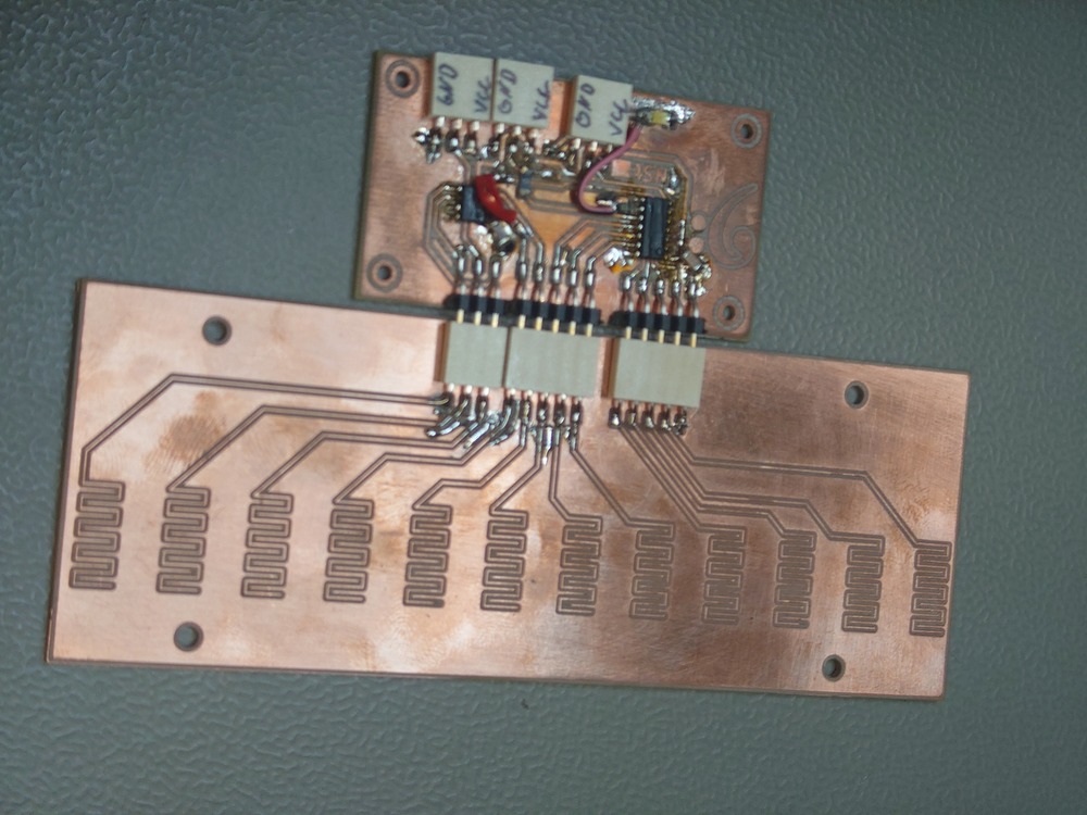
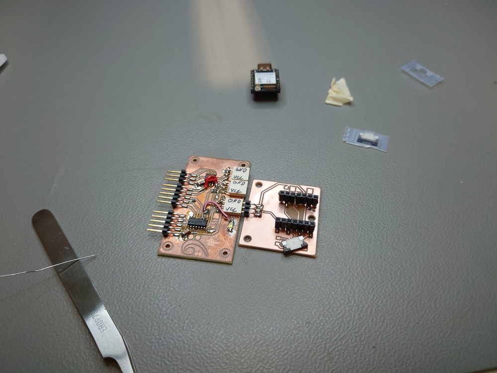
Note
All soldered above were fails -.-
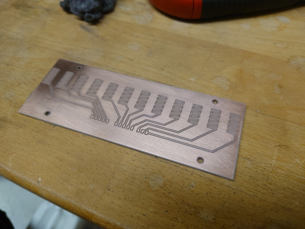
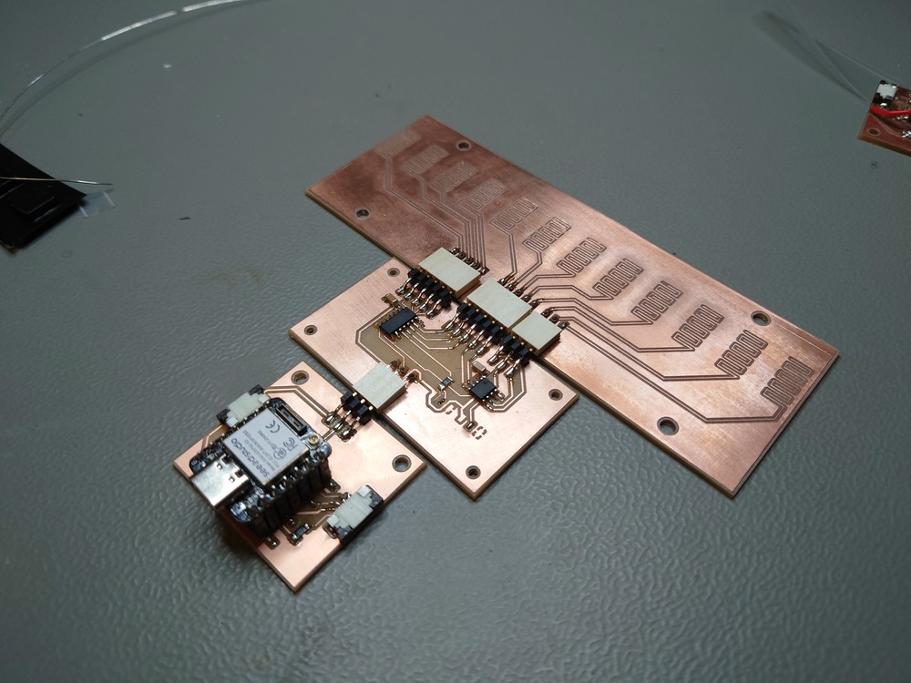
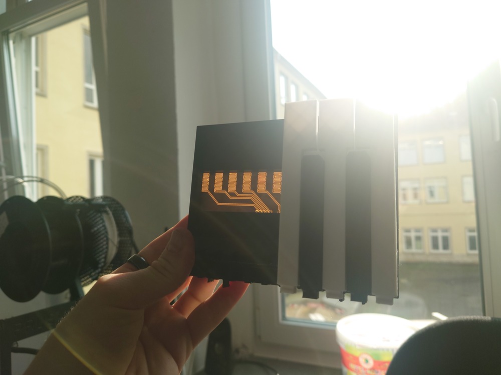
Final Working Boards
3D Printing
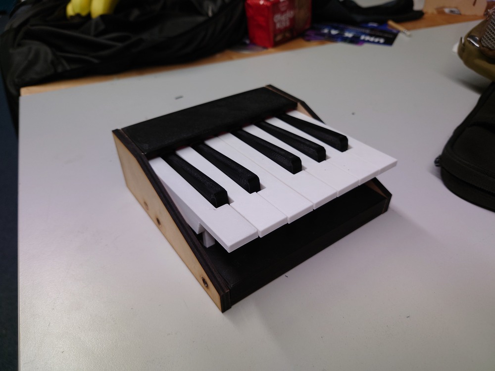
Testing the Mechanics
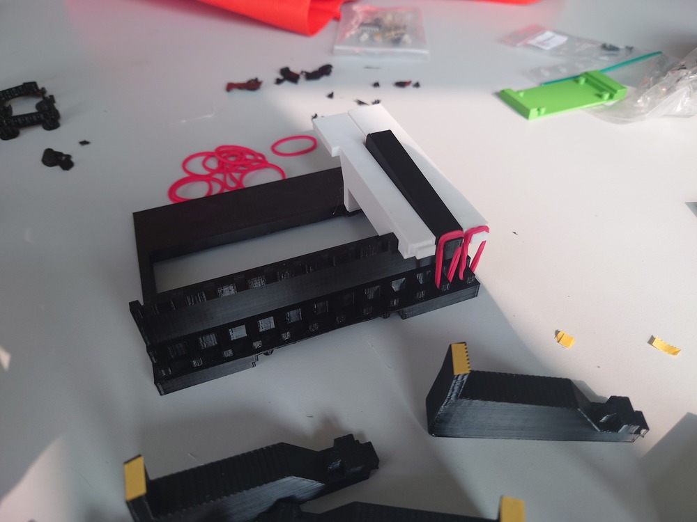
For more testing, see programming
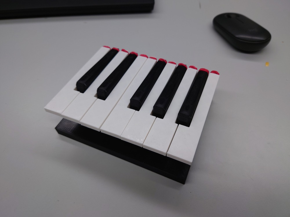
Final 3D Print

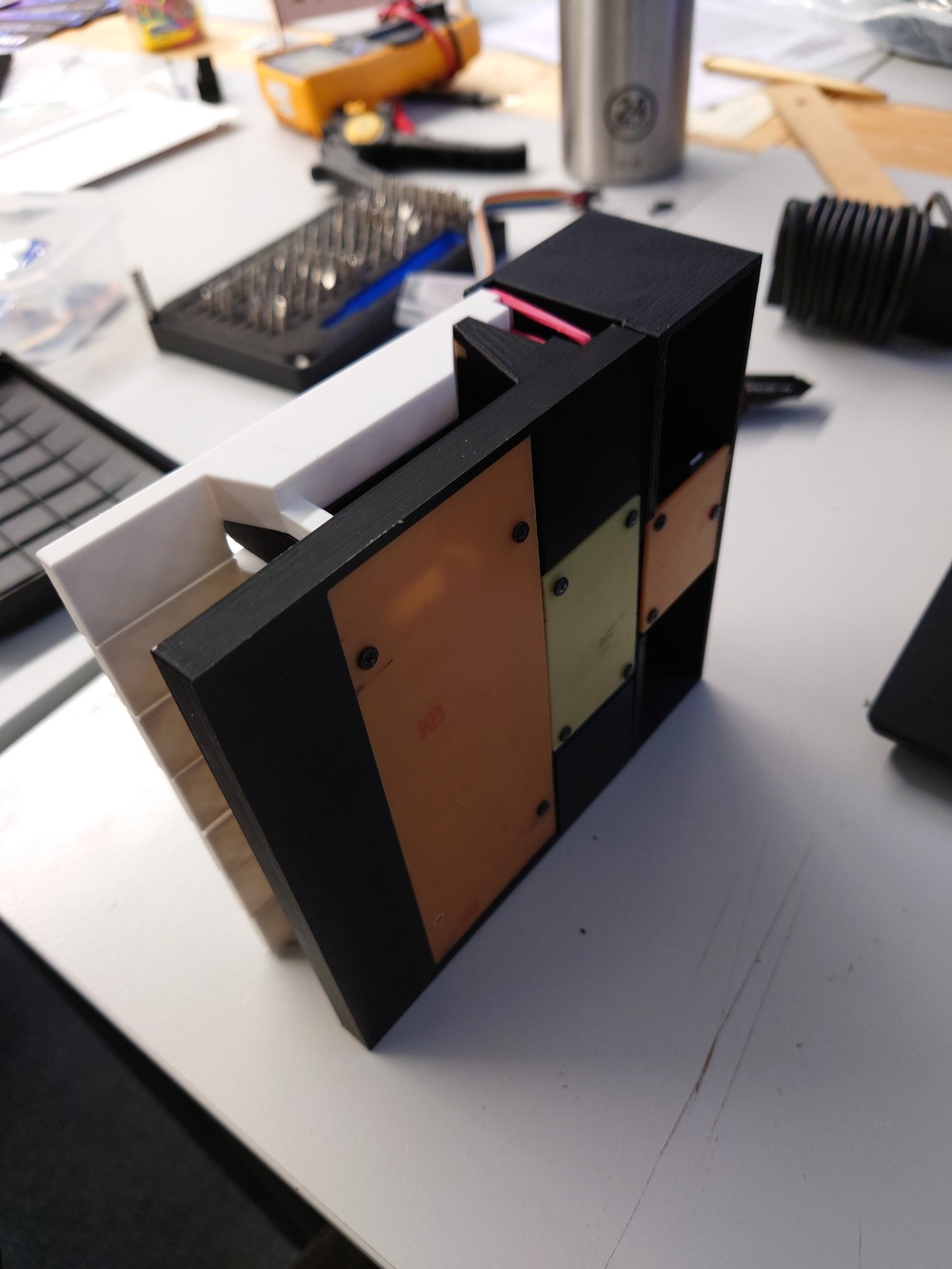
System Integration
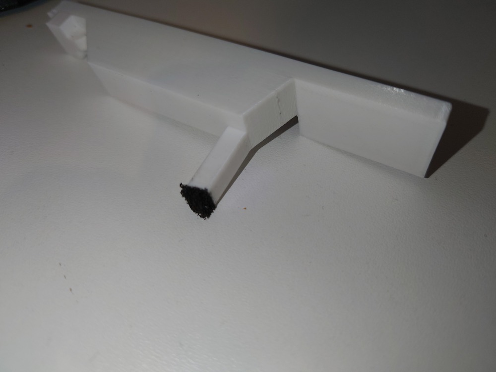
For the foam to stick onto the Keys I used double sided Tesa-Tape which worked extremely good actually on the 3D print and foam.
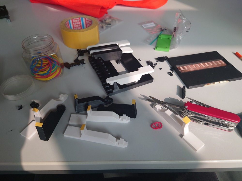
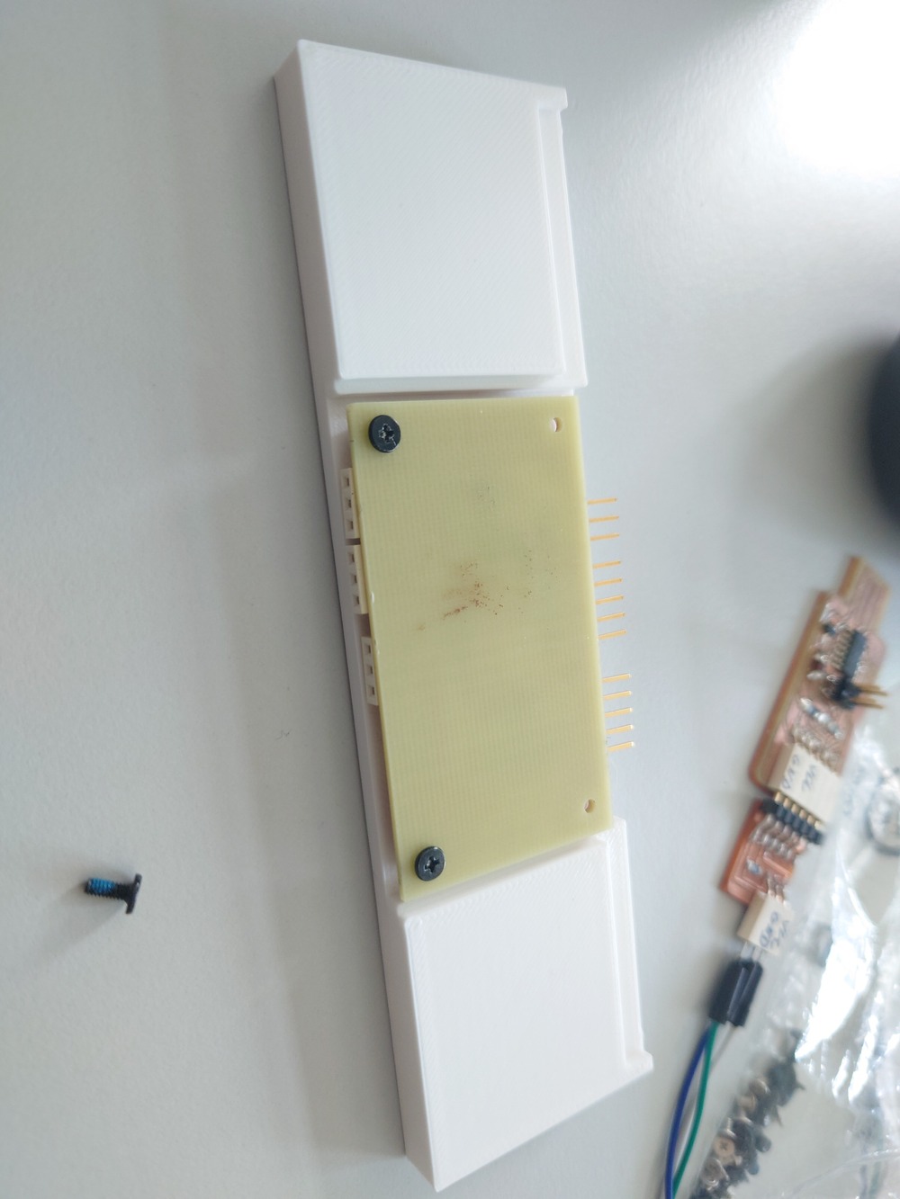
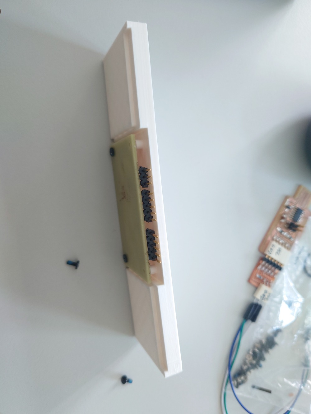
Here I tested if the board will fit
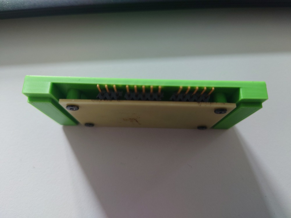
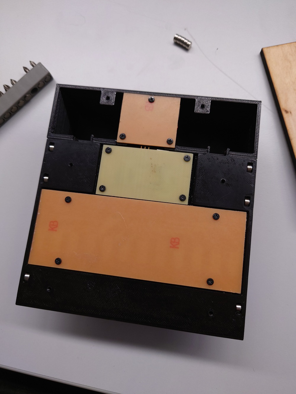
Here I tested the fit of all boards and the snap-fits:
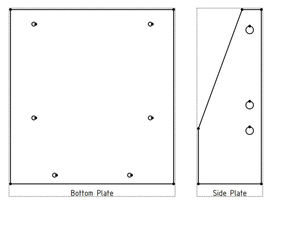
Laser Cutting
Prepair
In FreeCAD I used the ‘TechDraw’ Workbench to use the side of the designed models as a vector graphic.
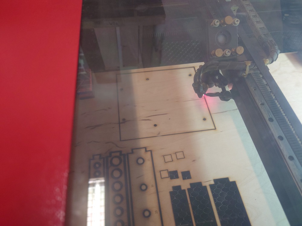
Cut
I used following settings for the 6.5mm wood:
Power: 80%
Speed: 7mm/s
Post Process
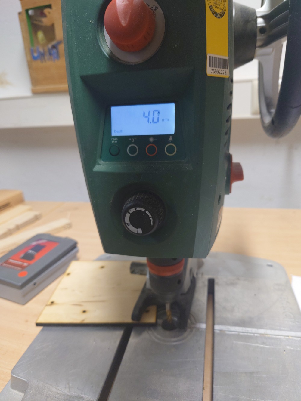
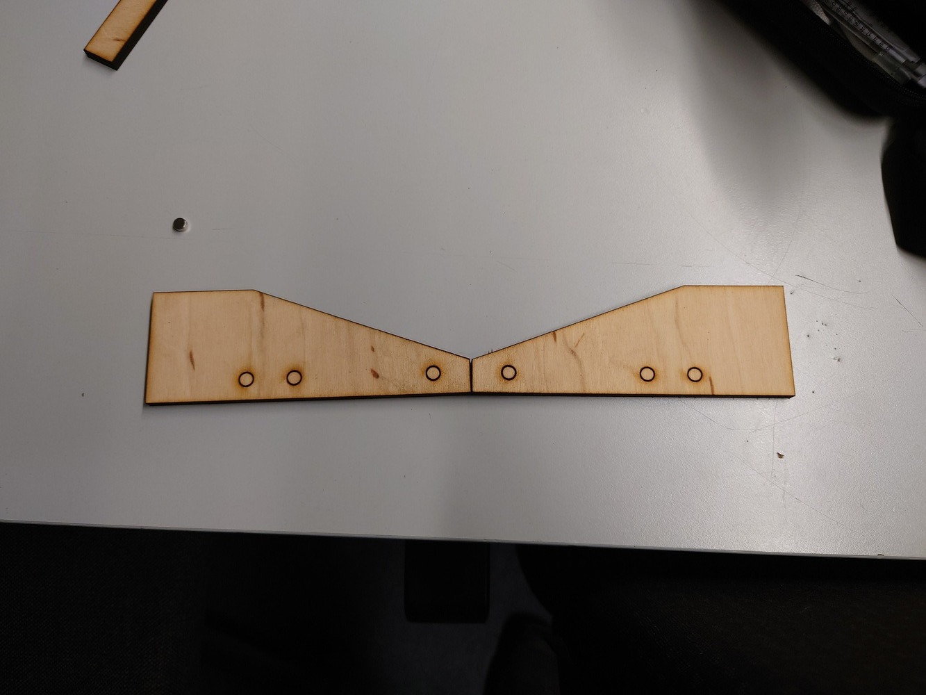 For the side panels I used less power and more speed to only mark the holes I later mill (not through!) with a pillar drill.
On our drill, I even had a display and could measure the distance, what a dream.
I also made a small countersink for the screws so the keyboard stand on an even plane.
And afterwards I also sanded the laser-cut side so it looked a bit cleaner.
Assembling
The I screwed down everything, placed magnets inside of the 3D print and side panels and snapped it together.
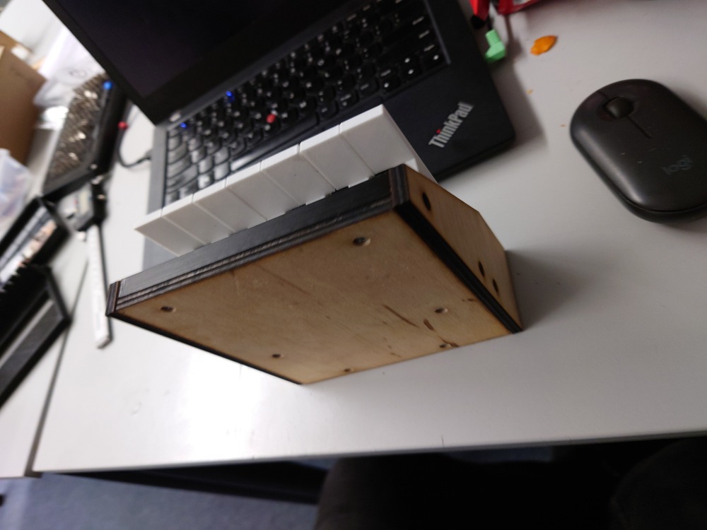
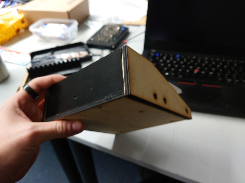
Final Result
 Made by Matthias