4. Embedded Programming - Week 4
4.1. Assignments
Embedded Programming
group assignment:
Demonstrate and compare the toolchains and development workflows for available embedded architectures
individual assignment:
browse through the data sheet for your microcontroller
write a program for a microcontroller,
and simulate its operation,
to interact (with local input &/or output devices)
and communicate (with remote wired or wireless connections)
extra credit: test it on a development board
extra credit: try different languages &/or development environments
4.2. Group Assignment
Group Assignment Documentation Group Documentation UNIKAT Wiki
I have experience with flashing and programming with micro-controller but reading about details of following ways to flash a micro-controller I find really useful to know:
4.2.1. General
Useful doc: MIT MTM documentation
2 general modes: 1. In-System Programming (ISP) - flash/program chip, when it is already mounted/integrated on the target system - convenient -> program, change and test on target system without removing 2. Pre-Programming - flash/program before integrating in target system - used in mass production where unified code is wanted across devices
4.2.1.1. Debug Access Port (DAP)
e.g.: CMSIS-DAP (for arm)
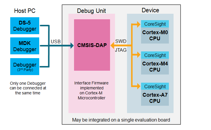
interface firmware for a debug-unit (connect debug port to USB on a pc)
Applications communicate with this unit, which reads devices infos shown via JTEG/SWD
4.2.1.2. Unified program and debug interface (UPDI)
proprietary programming interface like JTEG or SWD
for AVR micro-controller
need USB to serial converter
4.2.1.3. Serial Peripheral Interface (SPI)
synchronous full-duplex bus-system
master slave
4.2.2. Flashing Code to micro-controller - Toolchain Setup
I’ve chosen the RP2040 and the ESP32 family that I want to test flashing.
4.2.2.1. ESP32 with ESP-IDF
I’ve chosen the ESP-IDF because I don’t really like the Arduino-environment and I wanted to try out something new.
Setup
Installation
I’ve chosen to use my package manager to install it but basically you clone the repo:
git clone https://github.com/espressif/esp-idf
cd esp-idf
then you call the
install.shscript with the esp you want to use:
install.sh esp32s3
this then installs the required toolchain in the
.espressifdirectory, which then looks like this:
.espressif
├── dist                                                            # download artifacts
│   ├── esp32ulp-elf-2.38_20240113-linux-amd64.tar.gz
│   ├── esp-rom-elfs-20241011.tar.gz
│   ├── openocd-esp32-linux-amd64-0.12.0-esp32-20241016.tar.gz
│   ├── riscv32-esp-elf-14.2.0_20241119-x86_64-linux-gnu.tar.xz
│   ├── riscv32-esp-elf-gdb-14.2_20240403-x86_64-linux-gnu.tar.gz
│   ├── xtensa-esp-elf-14.2.0_20241119-x86_64-linux-gnu.tar.xz
│   └── xtensa-esp-elf-gdb-14.2_20240403-x86_64-linux-gnu.tar.gz
├── espidf.constraints.v5.4.txt
├── idf-env.json
├── python_env                                                      # python environments for the download tools and also the flash tools for the esp (esptool.py)
│   └── idf5.4_py3.13_env
│       ├── bin
│       ├── idf_version.txt
│       ├── include
│       ├── lib
│       ├── lib64 -> lib
│       └── pyvenv.cfg
└── tools                                                           # tools, compiler and libraries for the microprocessor
    ├── esp32ulp-elf
    │   └── 2.38_20240113
    ├── esp-rom-elfs
    │   └── 20241011
    ├── openocd-esp32
    │   └── v0.12.0-esp32-20241016
    ├── riscv32-esp-elf
    │   └── esp-14.2.0_20241119
    ├── riscv32-esp-elf-gdb
    │   └── 14.2_20240403
    ├── xtensa-esp-elf
    │   └── esp-14.2.0_20241119
    └── xtensa-esp-elf-gdb
        └── 14.2_20240403
Using esp-idf
then to use the tools, libraries, etc. you need to source the
export.shfile in the repo to have the tools available in your shell:
source export.sh
# or
./export.sh
Tip
I use a tool called direnv to not always source the file in a new terminal, it just automatically sources the file, when I’m in the directory, where I want to use the tools.
It checks for an
.envrcfilechecks, if you allowed it (for security, e.g. if you clone a repo with an .envrc, it gets executed and maybe does nasty things :|)
then executes the things in there, so mine looks like this:
source /opt/esp-idf/export.sh
So I have a development directory, where I have those tools and libraries.
For setting it up, you look on Github, but it is basically this in your .bashrc (if you use bash):
eval "$(direnv hook bash)"
then to flash the program, go to your development directory, and call:
idf.py set-target esp32s3   # our your esp to program
idf.py menuconfig           # optional, change flashing setting like which protocol for flashing
# in my case, the autodetect worked and i didn't need to set anything in flasher config
then for your project, use those commands to build and flash your device
idf.py build                    # build the hole project, may need some time
idf.py -p /dev/ttyACM0 flash    # /dev/ttyACM0 is just an example, may be named/mounted with another name
Programm
I just used a simple blink-example and reduced the code to a minimum so, that it is easier to understand.
Main File
For this flashing test, I just used this code and simplified the blink_example_main.c
[
#include <stdio.h>
#include "freertos/FreeRTOS.h"
#include "freertos/task.h"
#include "driver/gpio.h"
#include "esp_log.h"
#include "led_strip.h"
#include "sdkconfig.h"

static const char *TAG = "example";

#define BLINK_GPIO 7
#define CONFIG_BLINK_PERIOD 1000 // in ms

static uint8_t s_led_state = 0;


static void blink_led(void)
{
    /* Set the GPIO level according to the state (LOW or HIGH)*/
    gpio_set_level(BLINK_GPIO, s_led_state);
}

static void configure_led(void)
{
    ESP_LOGI(TAG, "Example configured to blink GPIO LED!");
    gpio_reset_pin(BLINK_GPIO);
    /* Set the GPIO as a push/pull output */
    gpio_set_direction(BLINK_GPIO, GPIO_MODE_OUTPUT);
}


void app_main(void)
{

    /* Configure the peripheral according to the LED type */
    configure_led();

    while (1) {
        ESP_LOGI(TAG, "Turning the LED %s!", s_led_state == true ? "ON" : "OFF");
        blink_led();
        /* Toggle the LED state */
        s_led_state = !s_led_state;
        vTaskDelay(CONFIG_BLINK_PERIOD / portTICK_PERIOD_MS);
    }
}
and cmake must look like this to include all files and libs from the esp-idf:
CMakeLists.txt
# The following five lines of boilerplate have to be in your project's
# CMakeLists in this exact order for cmake to work correctly
cmake_minimum_required(VERSION 3.16)

include($ENV{IDF_PATH}/tools/cmake/project.cmake)

set(CMAKE_EXPORT_COMPILE_COMMANDS ON)
project(blink)

idf_component_register(SRCS "blink_example_main.c"
                       INCLUDE_DIRS ".")
Notes
debugging/checking the serial output is very nice here, you can just read the output of the PORT (here /dev/ttyACM0) with, e.g.
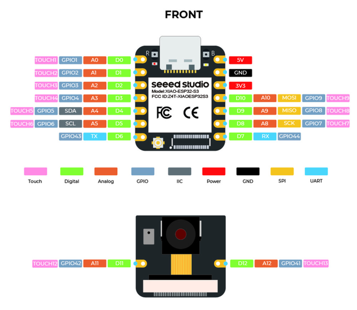
catorscreenand reed the messages :DI first had a problem finding the right pin number, the one used here I could find in the from XIAOs Pin image:
4.2.2.2. RP2040 with pico-sdk
Again just a blink program to demonstrate using the tool-chain.
Setup
Again, I used my package manager to install it, but again, you can just clone the repo
the bad thing here is, that there are git submodules, which you need to individually handle, which is -.-
here are the to setup files I used: pico-sdk and also needed somehow is the picotool
Then I’ve chosen the method, where you copy the pico_sdk_import.cmake file in my directory and adjusted my CMakeLists.txt and put following lines on top:
cmake_minimum_required(VERSION 3.13...3.27)

# initialize the SDK based on PICO_SDK_PATH
# note: this must happen before project()
include(pico_sdk_import.cmake)
set(CMAKE_EXPORT_COMPILE_COMMANDS ON)


# initialize the Raspberry Pi Pico SDK
pico_sdk_init()
Programm
I just used the Sourcecode from the RaspberryPi example and adjusted it to my setup.
#include "pico/stdlib.h"


#ifndef LED_DELAY_MS
#define LED_DELAY_MS 250
#endif

#define PICO_DEFAULT_LED_PIN 2

// Perform initialisation
int pico_led_init(void) {
    // A device like Pico that uses a GPIO for the LED will define PICO_DEFAULT_LED_PIN
    // so we can use normal GPIO functionality to turn the led on and off
    gpio_init(PICO_DEFAULT_LED_PIN);
    gpio_set_dir(PICO_DEFAULT_LED_PIN, GPIO_OUT);
    return PICO_OK;
}

// Turn the led on or off
void pico_set_led(bool led_on) {
    // Just set the GPIO on or off
    gpio_put(PICO_DEFAULT_LED_PIN, led_on);
}

int main() {
    int rc = pico_led_init();
    hard_assert(rc == PICO_OK);
    while (true) {
        pico_set_led(true);
        sleep_ms(LED_DELAY_MS);
        pico_set_led(false);
        sleep_ms(LED_DELAY_MS);
    }
}
Notes
here it was a bit harder to find out, which GPIO pin is which, but in the Schematics and in the Pin image from XIAO:
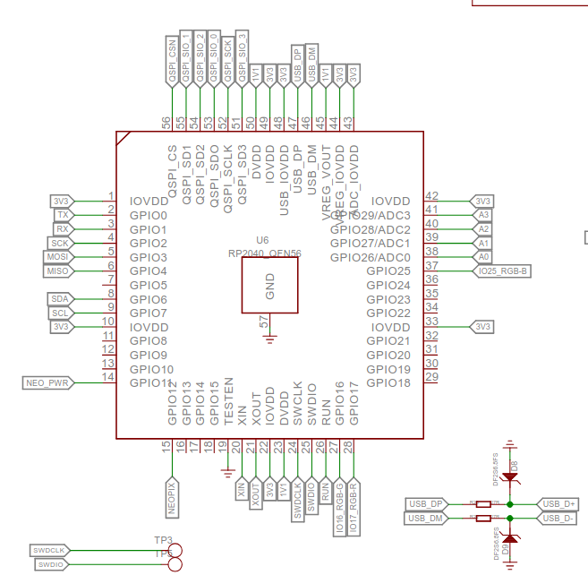
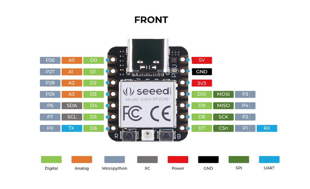
I used pin D8, which is named ‘SCK’ in the pin image and which is mapped to ‘GPIO2’
4.3. Individual Assignment
I’m going to choose the ESP32-S3 for my project, because of it has an extra peripheral for LED PWM and also an LCD interface (I’m not sure, if I’m going to implement my final project with LEDs or an LCD Display). It also has special DSP capabilities maybe for future additions to the keyboard behavior. And also with the size of the SRAM and Flash and the RF-Modules, there are many more things possible afterwards ;D.
4.3.1. Datasheet
4.3.1.1. Notable Informations
Boot
-   configuration default are set with [eFuse](https://espressif.com/documentation/esp32-s3_technical_reference_manual_en.pdf#efuse)
    -   once they are set to 1, they CANNOT be reverted!
-   with [Chip Boot Mode control](https://espressif.com/documentation/esp32-s3_technical_reference_manual_en.pdf#bootctrl), you can change the chip to boot from USB via JTAG/USB-OTG
-   Default messages are printed on both UART0 and USB Serial/JTAG
CPU
Xtensa ISA (Instruction Set Architecture)
FPU Integrated -> could be handy
128 bit data register available
Ultra Low Power Coprocessor available -> usable for extra programs available even when turned of
DMA controller (Direct Memory Access) for many peripherals like SPI I2S, AES, etc.
Memory
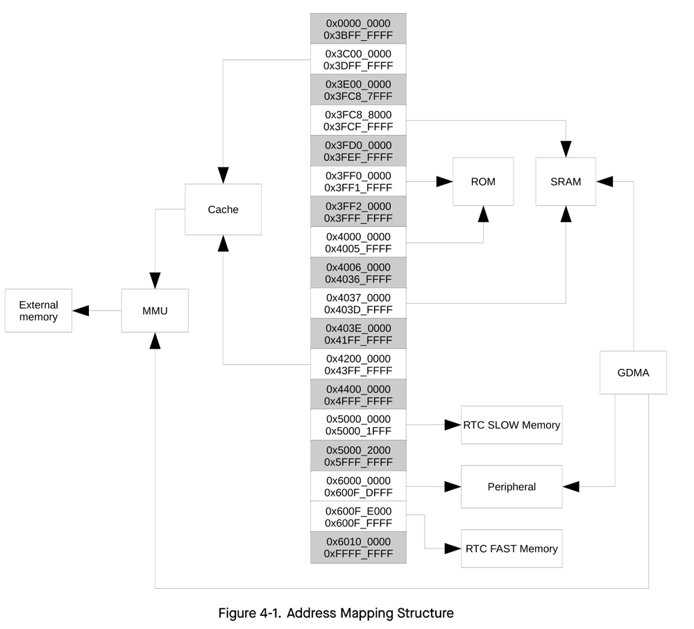
external Flash AND RAM possible (via SPI) up to 1GB (\0o0/)
eFuse for one time write private keys (AES, RSA, etc.)
System Components
Reset
4 Levels: CPU Reset, Core Reset, System Reset, Chip Reset
Power Management Unit (PMU)
very fine granular power Management possible
4 Predefined modes:
Active mode
Modem-sleep-mode
Light-sleep mode
Deep-sleep mode
uses different ‘Power Domains’ -> e.g.: digital power domain, RTC power domain, etc.
Permission Control
checks permissions for accessing slave modules (memory, peripherals, etc.) when in ‘Secure-World’
throws interrupt on illegitimate access
switch to Secure-World and non-secure world only via reset of chip
Cryptography/Security
has hardware Components for:
AES
SHA
RSA
HMAC -> very nice for network communication
Clock Glitch Detection
can detect Clock glitches from external clocks (cool :O) signals are then blocked
RNG
can generate true random number sequences from peripherals, yeah
Peripherals
TWAI - Two-wire Automotive Interface
multi-cast multi-master protocol
error detection/signaling
inbuilt message priorities
integrated USB Serial/JTAG Controller
also used for flashing
-
3 controller (up to 5Mbps)
automatic baud rate detection of input
usable as wake-up source
-
2 interfaces, up to 800kbit/s
LCD Controller
pins from GPIOs
-
integrated; generates digital waveforms
-
could be relevant, if I want to use something like this
integrated, detect variations induced by finger or
Bluetooth LE
1Mbps PHY or 2Mbps
Listen before talk
Electrical Characteristics
max and recommended ratings for power supply and current consumption in modes
DC Output
ADC
Reliability
RF Characteristics
Radio bands for WIFI and Bluetooth LE Reception/Sending
4.3.2. Programming
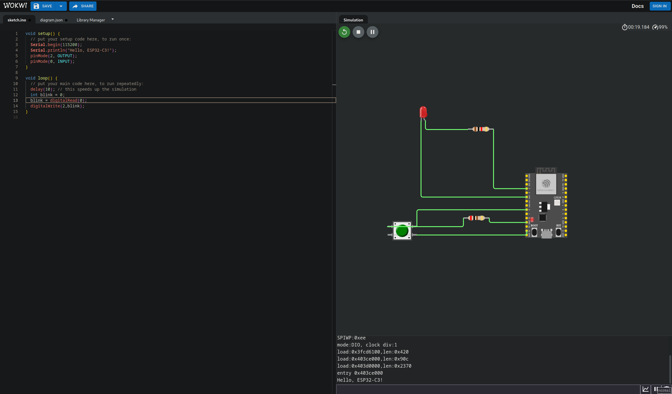
I tried simulating but I didn’t liked it very much. I don’t want an account, only visual studio code as IDE supported, I would like to simulate locally. Here a simple program which turns the led on with the button:
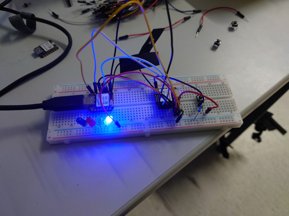
So I implemented a mall program that shifts some bits on the user side (a simple version of an LFSR) and on another ESP32-S3 receives the sequences and shows it with LEDS:
Sender
#include <stdint.h>
#include <stdio.h>
#include "freertos/FreeRTOS.h"
#include "freertos/task.h"
#include "driver/gpio.h"
#include "esp_log.h"
#include "sdkconfig.h"

static const char *TAG = "Rofl";

#define GPIO_OUT_BIT_0 44
#define GPIO_OUT_BIT_1 7
#define GPIO_OUT_BIT_2 8
#define GPIO_OUT_BIT_3 9
#define GPIO_BUTTON 43

static uint8_t s_led_state = 0;


// function to easily set the bits
static void send_bits(int8_t bitmask)
{
    // using bit-operation and a bit mask ,where every bit stands for an led to easily set the bits high
    gpio_set_level(GPIO_OUT_BIT_0, bitmask & 1); // first bit
    gpio_set_level(GPIO_OUT_BIT_1, bitmask & 2); // second bit
    gpio_set_level(GPIO_OUT_BIT_2, bitmask & 4); // third bit
    gpio_set_level(GPIO_OUT_BIT_3, bitmask & 8); // fourth bit
}

// initial configuration of the bits
static void configure_gpios(void)
{
    ESP_LOGI(TAG, "Configure GPIOs!");
    // reset the pin to clear the current value
    gpio_reset_pin(GPIO_OUT_BIT_0);
    gpio_reset_pin(GPIO_OUT_BIT_1);
    gpio_reset_pin(GPIO_OUT_BIT_2);
    gpio_reset_pin(GPIO_OUT_BIT_3);
    gpio_reset_pin(GPIO_BUTTON);
    // set pins to output and input mode accordingly
    gpio_set_direction(GPIO_OUT_BIT_0, GPIO_MODE_OUTPUT);
    gpio_set_direction(GPIO_OUT_BIT_1, GPIO_MODE_OUTPUT);
    gpio_set_direction(GPIO_OUT_BIT_2, GPIO_MODE_OUTPUT);
    gpio_set_direction(GPIO_OUT_BIT_3, GPIO_MODE_OUTPUT);
    gpio_set_direction(GPIO_BUTTON, GPIO_MODE_INPUT);
}


void app_main(void)
{

    configure_gpios();

    int8_t seq = 117;

    // on button press, calculate one round of the linear feedback shift register and wait a bit
    while (1) {

        if (gpio_get_level(GPIO_BUTTON)) {

            // shift register, simple PRNG
            int8_t seq_shift_1 = seq >> 1;
            seq = seq ^ seq_shift_1;

            send_bits(seq);
        }

        vTaskDelay(500 / portTICK_PERIOD_MS);
    }
}
Receiver
#include <stdint.h>
#include <stdio.h>
#include "freertos/FreeRTOS.h"
#include "freertos/task.h"
#include "driver/gpio.h"
#include "esp_log.h"
#include "sdkconfig.h"

#define GPIO_LED_1 1
#define GPIO_LED_2 2
#define GPIO_LED_3 3
#define GPIO_LED_4 4
#define GPIO_LED_BIT_0 44
#define GPIO_LED_BIT_1 7
#define GPIO_LED_BIT_2 8
#define GPIO_LED_BIT_3 9

static const char *TAG = "Lol";

static uint8_t s_led_state = 0;


// set the level accordingly to the received bits on the pins
static void update_bits(void)
{
    gpio_set_level(GPIO_LED_1,gpio_get_level(GPIO_LED_BIT_0));
    gpio_set_level(GPIO_LED_2,gpio_get_level(GPIO_LED_BIT_1));
    gpio_set_level(GPIO_LED_3,gpio_get_level(GPIO_LED_BIT_2));
    gpio_set_level(GPIO_LED_4,gpio_get_level(GPIO_LED_BIT_3));
}

static void configure_gpio(void)
{
    // same as above
    ESP_LOGI(TAG, "Configure GPIOs!");
    gpio_reset_pin(GPIO_LED_1);
    gpio_reset_pin(GPIO_LED_2);
    gpio_reset_pin(GPIO_LED_3);
    gpio_reset_pin(GPIO_LED_4);
    gpio_reset_pin(GPIO_LED_BIT_0);
    gpio_reset_pin(GPIO_LED_BIT_1);
    gpio_reset_pin(GPIO_LED_BIT_2);
    gpio_reset_pin(GPIO_LED_BIT_3);
    gpio_set_direction(GPIO_LED_1, GPIO_MODE_OUTPUT);
    gpio_set_direction(GPIO_LED_2, GPIO_MODE_OUTPUT);
    gpio_set_direction(GPIO_LED_3, GPIO_MODE_OUTPUT);
    gpio_set_direction(GPIO_LED_4, GPIO_MODE_OUTPUT);
    gpio_set_direction(GPIO_LED_BIT_0, GPIO_MODE_INPUT);
    gpio_set_direction(GPIO_LED_BIT_1, GPIO_MODE_INPUT);
    gpio_set_direction(GPIO_LED_BIT_2, GPIO_MODE_INPUT);
    gpio_set_direction(GPIO_LED_BIT_3, GPIO_MODE_INPUT);
}


void app_main(void)
{

    configure_gpio();

    // just continuously update the LEDS
    while (1) {
        ESP_LOGI(TAG, "Update the LEDs!");
        update_bits();

        vTaskDelay(10 / portTICK_PERIOD_MS);
    }
}
So it’s like a simple pseudo random number generator which uses a seed to generate a small random sequence.