5. 3D Scanning and Printing - Week 5
5.1. Assignments
3D Scanning and Printing
group assignment
test the design rules for your 3D printer(s)
individual assignment
design and 3D print an object (small, few cm, limited by printer time)
that could not be made subtractively
3D scan an object (and optionally print it)
5.2. Group Assignment
For the Group Assignment I chose to use it and finally setup and optimise my printer at home, but also below the links to our printers in the lab.
5.2.1. Fab Lab Printer
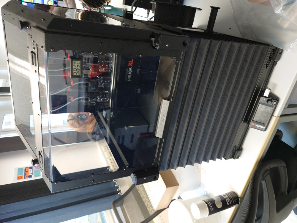
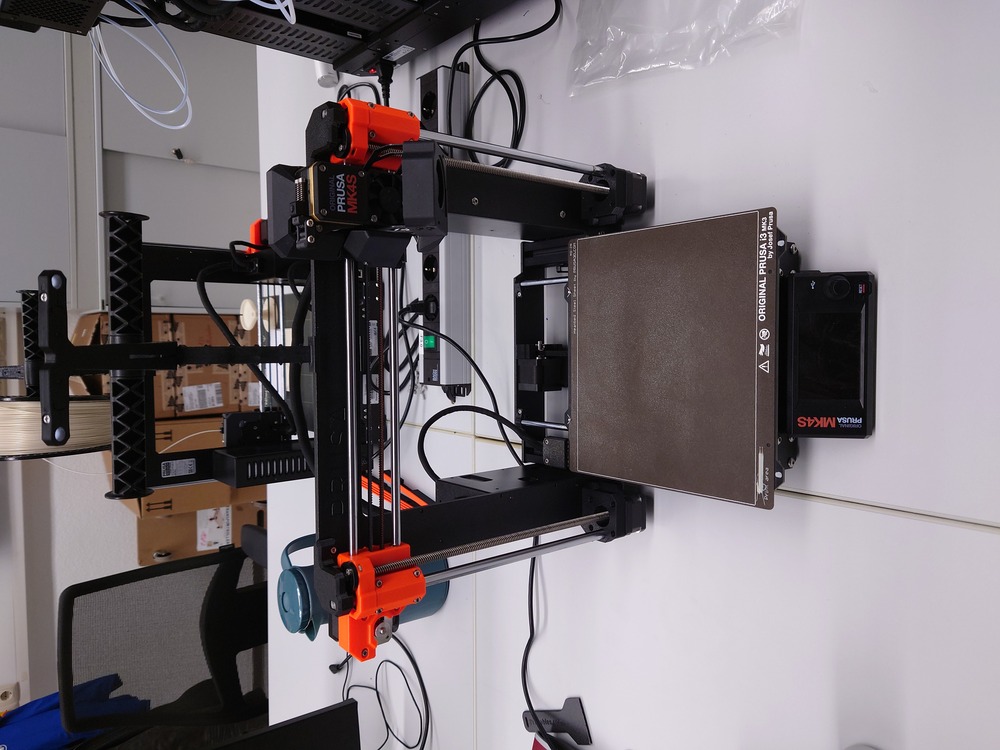
In our Lab, we have:
Prusa XL
3 Prusa MK4s
5.2.1.1. Design Rules Group Page
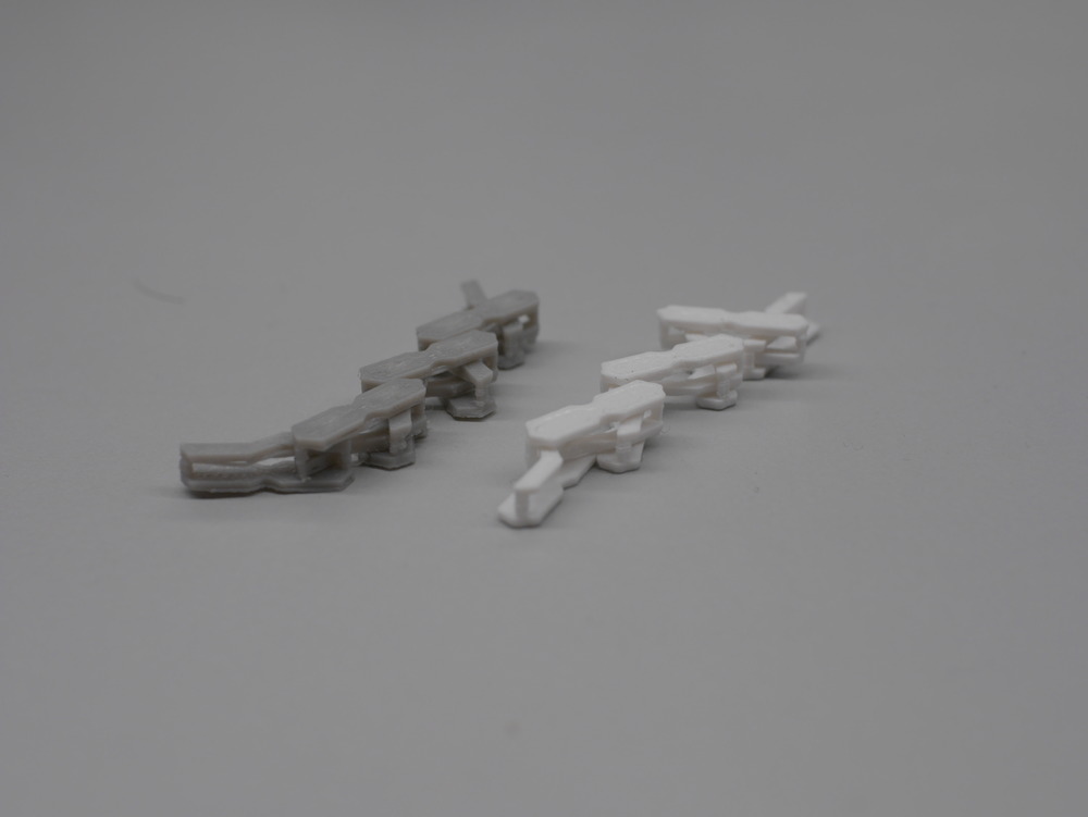
And here our printed design-rules objects:
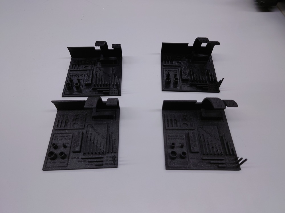 Ordered like this:
XL PETG     |       MK4s PETG
-----------------------------
XL PLA      |       MK4s PLA
5.2.2. My Printer
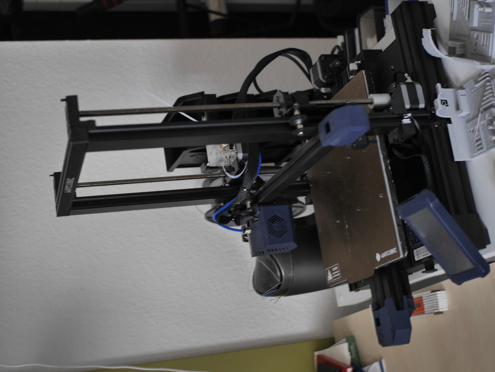
I have a Anycubic Vyper @home (FDM).
5.2.2.1. Initial Setup
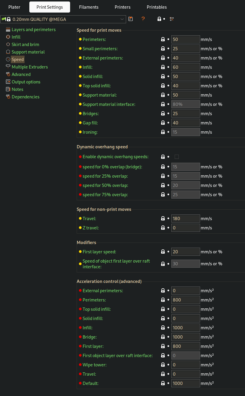
I first used the Anycubic i3 preset in the Prusa Slicer. For the Initial Setup, I changed following things:
Printable Volume: 245 x 245 x 260 mm (in the Printer Setup)
Nozzle: 0.4mm
Also tuned a bit the speed values:
5.2.2.2. Design Rules Test
We used following Modell for testing the design rules:
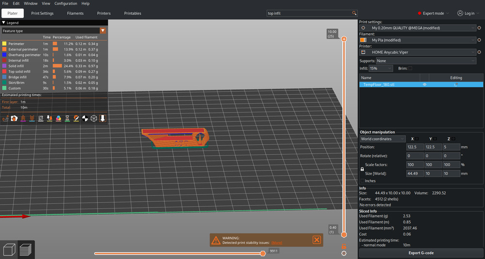
Also I adjusted the print settings a little(just layer hight to 0.4mm, so the print won’t take that long).
Took 3h ._.
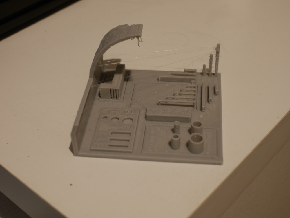
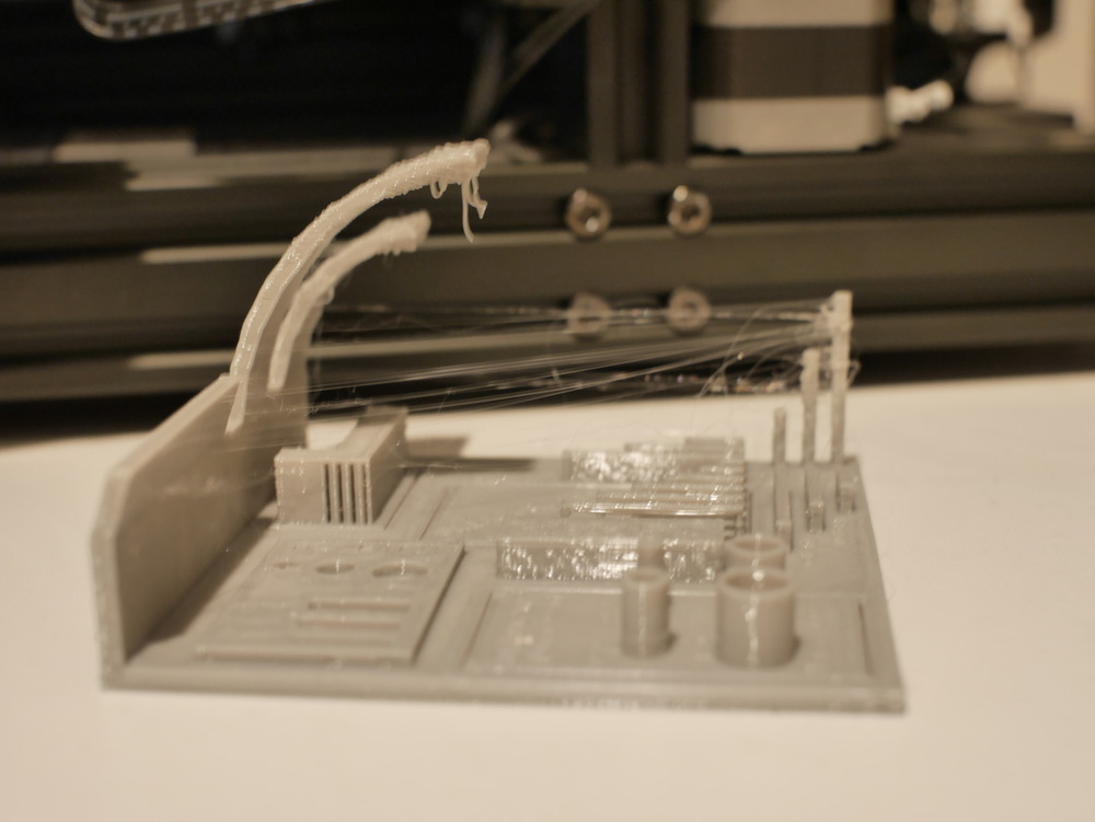
Outcome
First, if you look closer, you may notice a little stringing, so I first wanted to optimise the print first, before evaluating.
5.2.2.3. Optimisation for my Filament
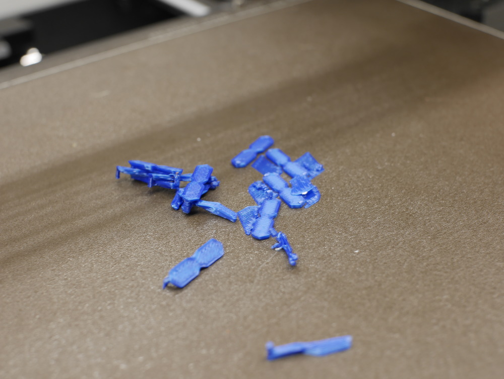
For Optimisation, I printed many little Test Object, where I changed the Filament temperature for each one to check, for wich temperature my PLA Filament works best:
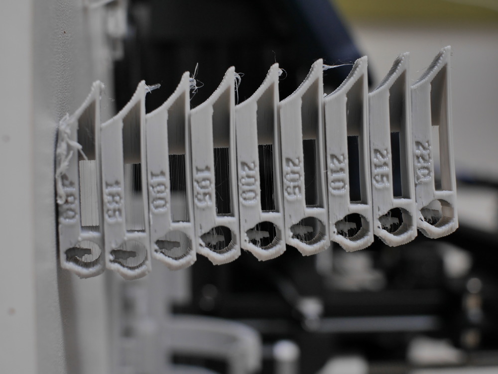
So I found out, that 210°C is optimal for it. Then I reprinted the design rule test again:
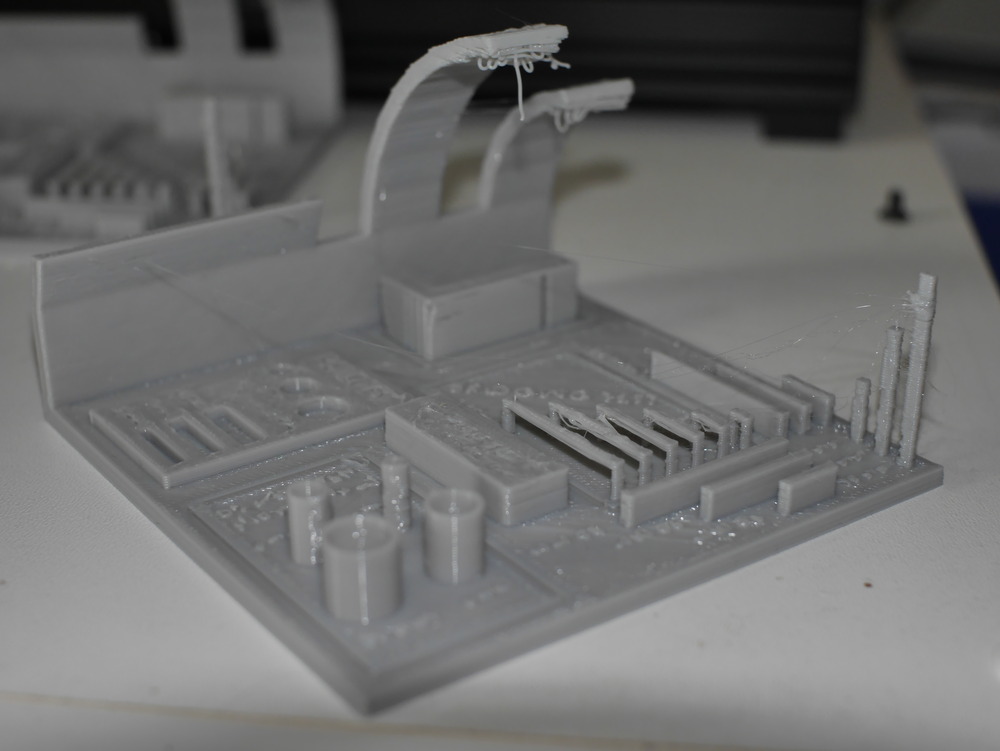
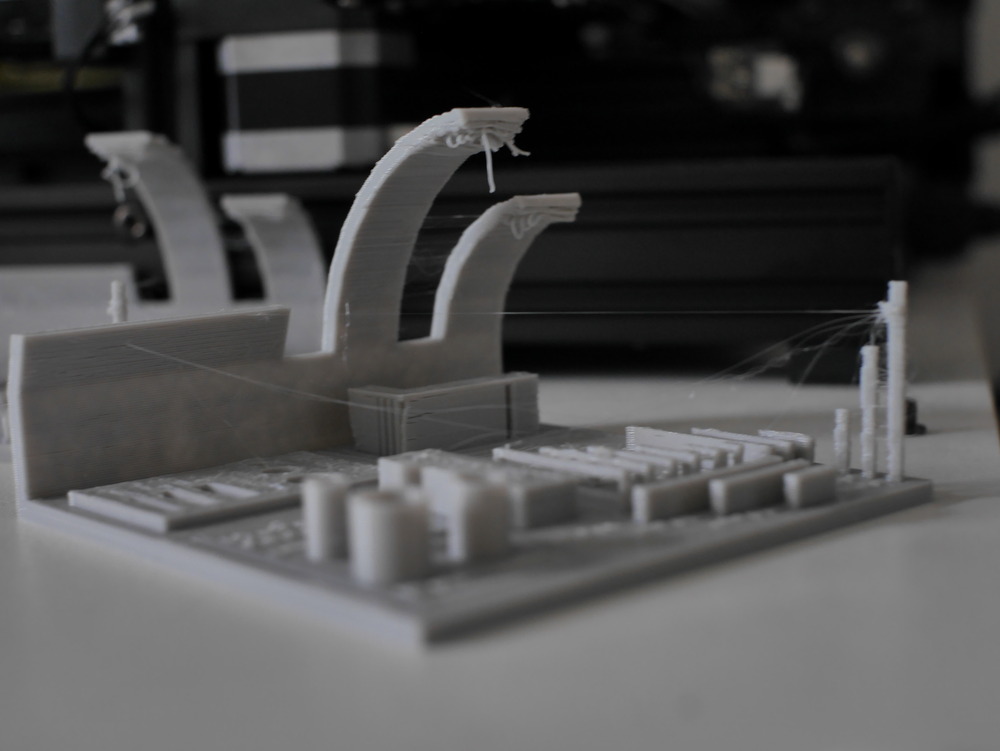
As seen above, it’s still not optimal but unfortunately I couldn’t find more time to optimise more. Also seen is that the bridging is inconsistent, which also could be optimised.
The next steps would be:
check and adjust retraction speed and extrusion rate
adjust travel speed
adjust bridge speed (and printing speeds in general)
Note:
last layer is a bit bigger on the measured values
where i could, i measured the layers below
i definitely also need to adjust the extrusion rate
5.2.2.4. Design Rules Outcome
So from the above test-print I got following design-rules:
~15mm Bridge is ok
~65° overhang is fine
Diameter test:
Model value |
Real Value |
Difference |
|---|---|---|
10mm |
9.8mm |
0.2mm |
8mm |
7.8mm |
0.2mm |
6mm |
6mm |
(wow \o.o/) |
4mm |
3.8mm |
0.2mm |
Hole test:
Model value |
Real Value |
Difference |
|---|---|---|
8mm |
7.8mm |
0.2mm |
6mm |
5.7mm |
0.3mm |
4mm |
3.8mm |
0.2mm |
Slit test (like Hole test, first it the width):
Model value |
Real Value |
Difference |
|---|---|---|
14mm |
14.8mm |
0.2mm |
4mm |
3.8mm |
0.2mm |
3mm |
2.8mm |
0.2mm |
2mm |
1.7mm |
0.3mm |
Length test:
Model value |
Real Value |
Difference |
|---|---|---|
x: |
||
10mm |
10.1mm |
0.1mm |
20mm |
20.1mm |
0.1mm |
30mm |
30.2mm |
0.2mm |
y: |
||
10mm |
10.2mm |
0.2mm |
20mm |
20.2mm |
0.2mm |
30mm |
30.2mm |
0.2mm |
5.3. Individual Assignment
5.3.1. Printing
5.3.1.1. Design the Object
For printing, I decided to do a chained model because i wanted to try it out. As a base for the chain, I’ve chosen the Cool S many may know. And because of the Print-In-Place design of the connection the chain would be hard to produced subtractively.
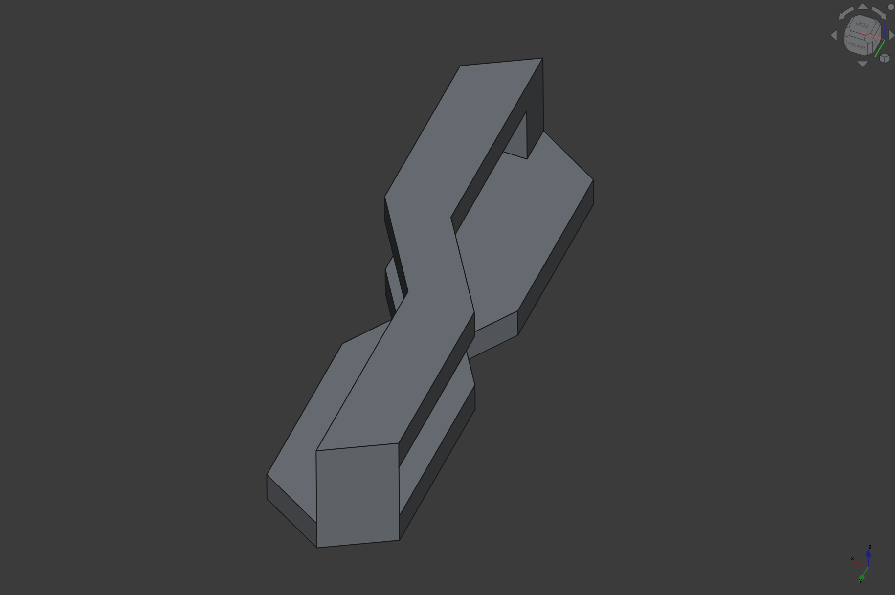
STL Preview (TODO)
And I also wanted to try out the new assembly module in FreeCAD, and its pretty nice :D :
But im not a pro in this, maybe, there was a better way implementing this kind of design. Also I took in consideration the bridging value from the design rules but I should have more strict with it…
5.3.1.2. Printing
@Home
So first I sliced it with minimal print-on support on the floating parts:
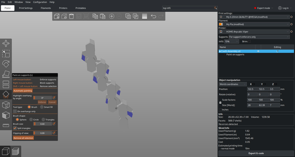
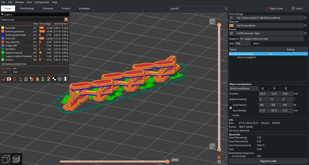
The first version I printed was not that nice, the bridges where sagging a bit, causing it to not work properly/get easily destroyed…
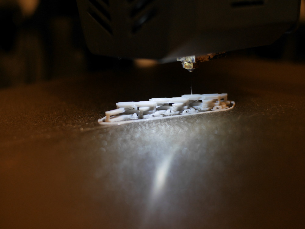
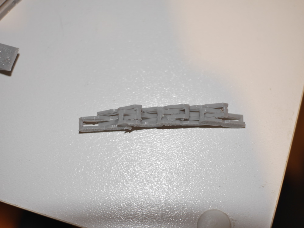
I tried to print it smaller, but this caused also the connection from the above and below part to be very unstable/easily destroyed. But this is also a design flaw in my files, I could have modeled it stronger on that part.
@LAB
In our Lab, the printers where (obviously) way better and I got a good result, printed with the MK4s and PETG:
But I also tried PLA and when I tried to remove it, I destroyed it, so I guess my design was not very good i conclude…
5.3.2. Scanning
5.3.2.1. Approaches
For the approaches I wanted to try out a SLAM based and Photogrammetry, and we also we had a finished solution from Creality in our lab.
SLAM with RTAB-Map
I chose RTAB-Map for this apprach, where I can choose the sensors to work with (also works with ROS, where I found RTAB-Map at Work from a colleague).
I used the Nix version from RTAB-Map because it was already prebuild and ready to work with, but you need nixGL for it to work, or you already use NixOs.
nix-shell -p rtabmap
nixGL rtabmap
Kinect 1
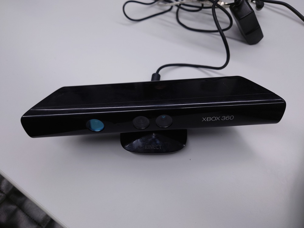
First, I need to install the Kinect Package (because I use the nix Variant, I only needed this Udev rule in my system).
With the good old Kinect 1 to USB Adapter I hooked it up to my pc and could start scanning, after unloading not needed kernel modules in Linux, those are not needed for freenect and cause the camera to not work.
sudo modprobe -r gspca_main gspca_kinect
And then I measured:
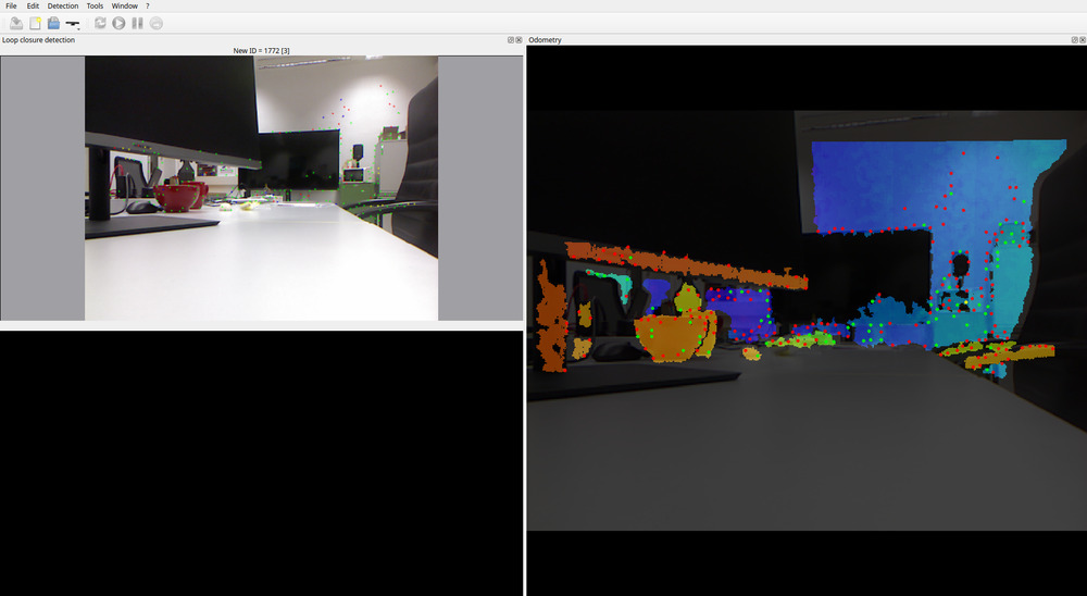
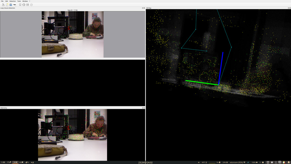
And here the Point clouds I measured:
First Small Scan
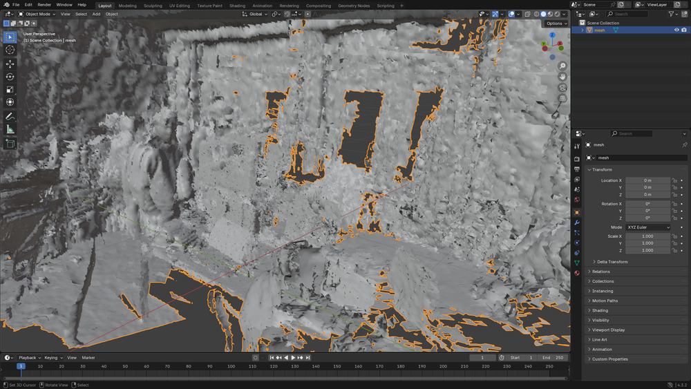
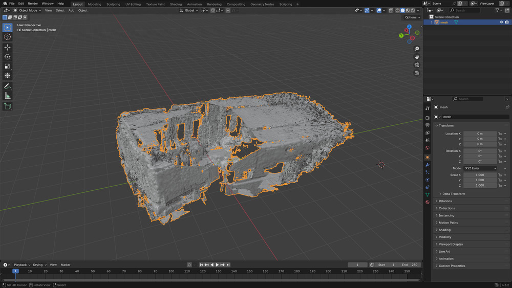
Second Bigger Scan
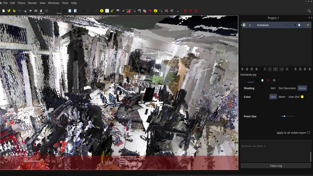
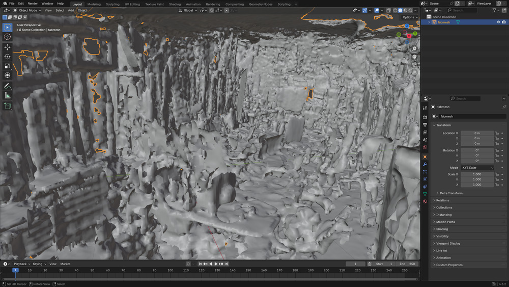
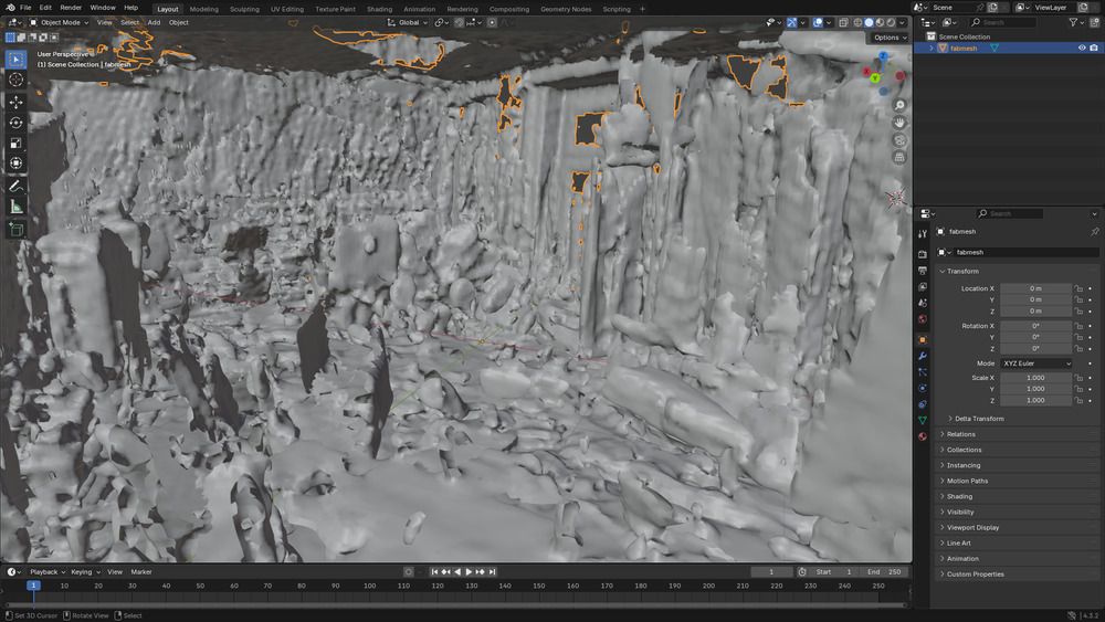
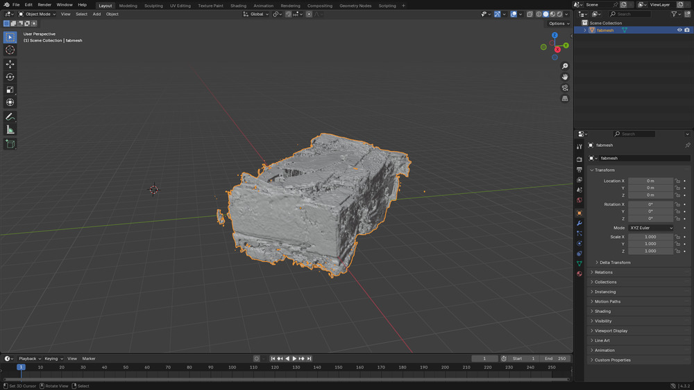
unfortunately they where not that good, because the localisation was not very precise, leading to not correct coordinates of the points. I could have measured more but I couldn’t find time (and I already measured ~30min)
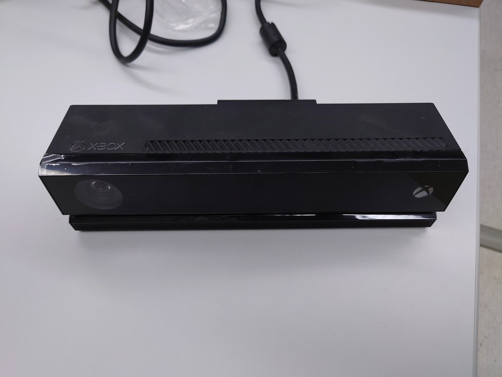
Kinect 2
I tried -.-
Notes
It’s kinda hard to get it working, even when you know, how a bit
I wasted to much time trying to get the kinect 2 working, I should have used ROS, I think(and ask my colleague)
Photogametry
unfortunately I didn’t managed to try this out in time
Creality Raptor
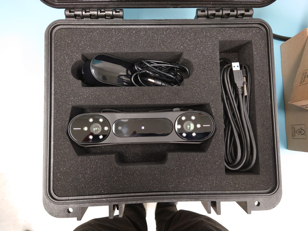
didn’t managed that either