3. Computer-Controlled Cutting - Week 3
3.1. Assignments
Computer-Controlled Cutting
group assignment:
do your lab’s safety training
characterize your lasercutter’s focus, power, speed, rate,
kerf, joint clearance and types
individual assignment:
cut something on the vinylcutter
design, lasercut, and document a parametric construction kit,
accounting for the lasercutter kerf,
which can be assembled in multiple ways,
and for extra credit include elements that aren’t flat
3.2. Group Assignment
3.2.1. Safety Training
Important Learnings
in laser cutting, there should never be smoke/smell!!
wear safety glasses and keep the laser case shut to be save
don’t cross lase line if on!! turn of before making adjustments
3.2.2. How to use our laser
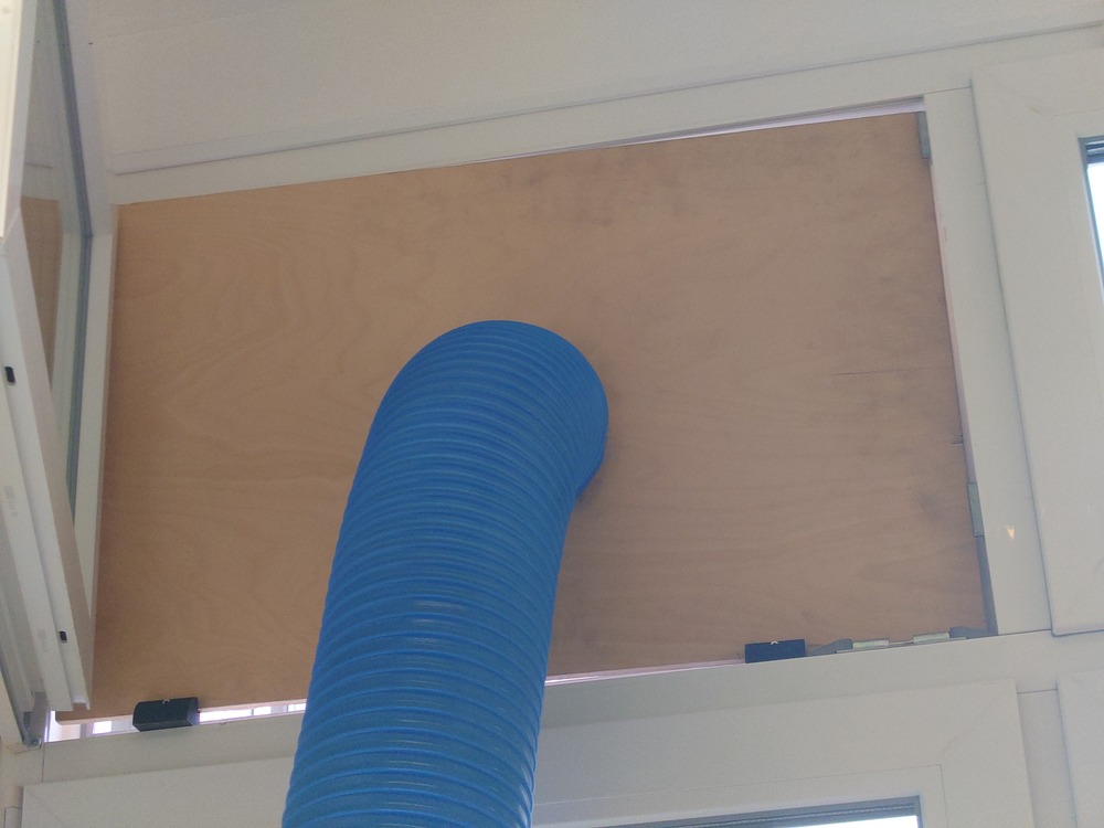
Setup Ventilation output on window
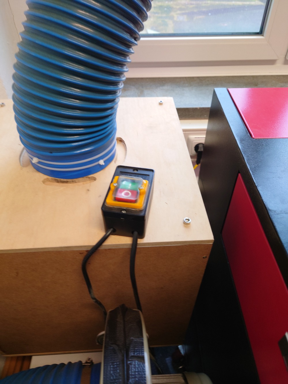
Turn the vent on
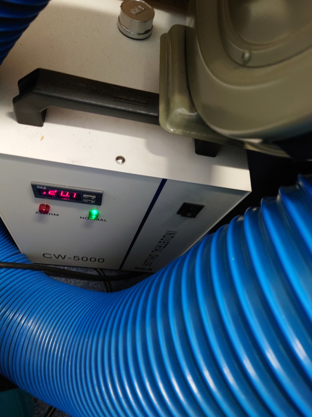
Turn the chiller on
behind a tube
first it lights up red and beeps 3 times but turns green after it
Flip the switch for the laser cutter -> laser not on, separate switch
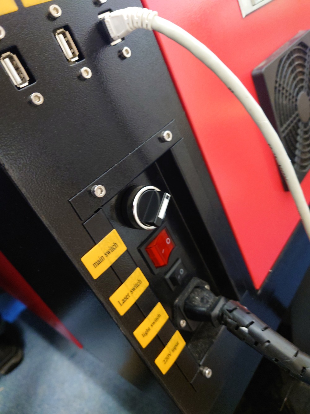
Now the Laser is ready for Usage.
Turn on light on the side-panel
Adjust leveling
use acryl-distance holder to set the distance between laser and bed to it (until it scratches the laser a bit)
buttons on the right side
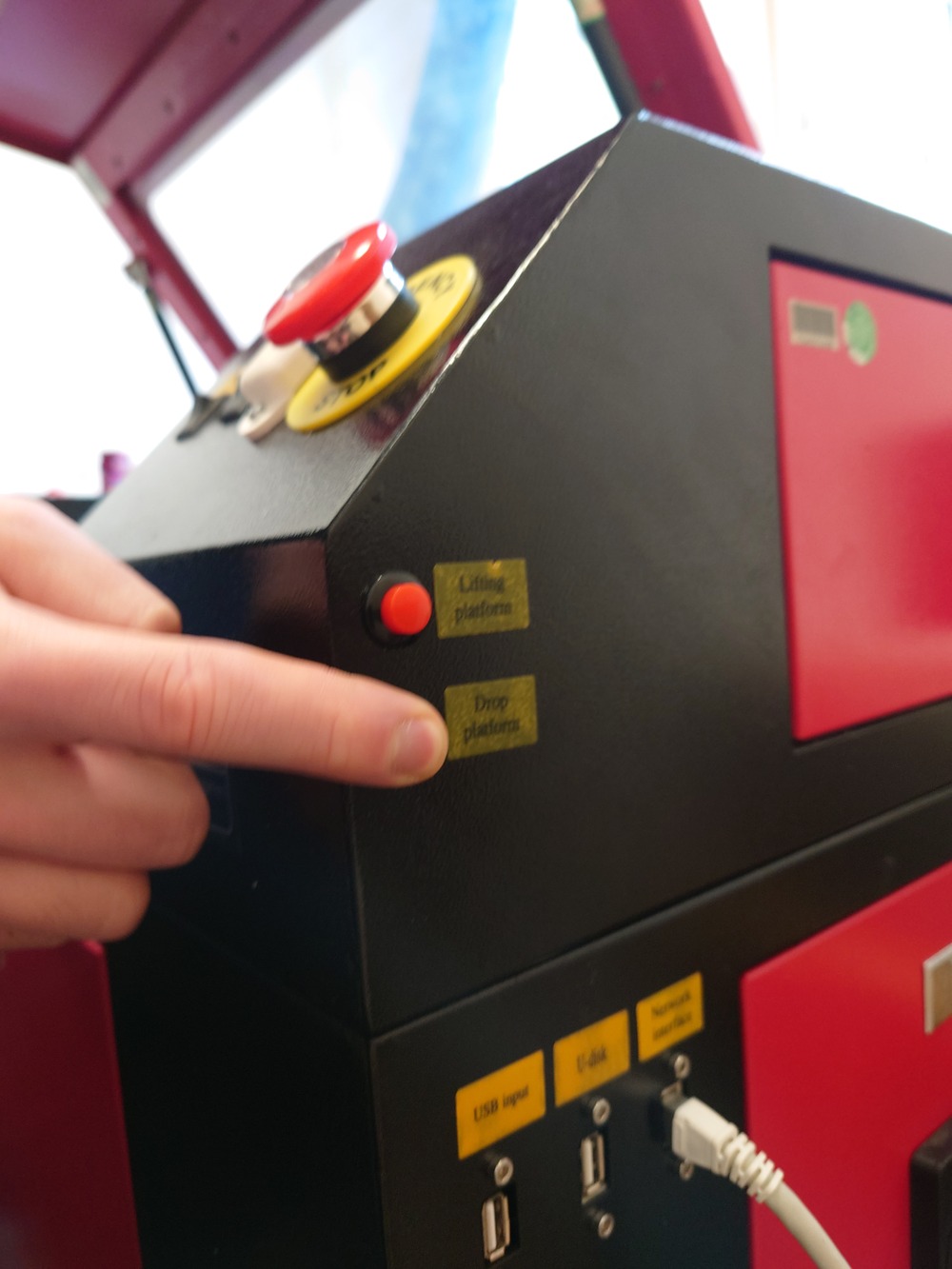
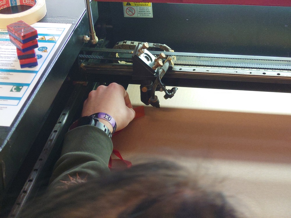
Set the local origin
on the front-panel there is a switch to turn on adjust laser -> PRESS IT
now use the laser to set the local origin, if needed
‘Esc’ Button on the top panel returns to local origin
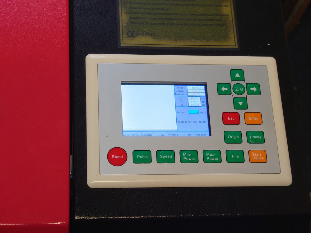
Choose uploaded file on machine to print (also upload and start is possible in RDWorks)
3.2.2.1. Additional Notes
left side of the bed is flat -> use for testing/configuration
Use ‘Frame’-Button on top panel to lookup the frame of the file to cut
‘Esc’ cancels program
3.2.3. Parameter
3.2.3.1. General Infos
Focus : Point in Space, where focal point of the lens is and so the cut of the laser the cleanest
Power : Power on the laser used for cutting/engraving strength : -> to strong == burn : -> to weak == no cut/not visible engrave
Min/Max Speed : exact max and min speed for laser-movement : -> to slow == to deep engraved/to much cut or burning : -> to fast == no/to low cut/engrave
Rate : For engraving the distance between the different lines/dots
Kerf : Part that is burned away : -> Diameter of the laser beam : -> needs to be calculated on model creation/design
Joint clearance: : -> even though the
Software: RDWorks
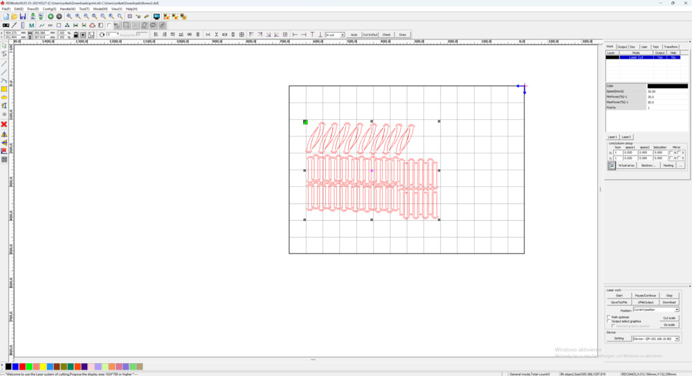
3.2.3.2. Determining values for our cardboard
For determining the values, we used following 3 methods:
3.2.3.3. Kerf
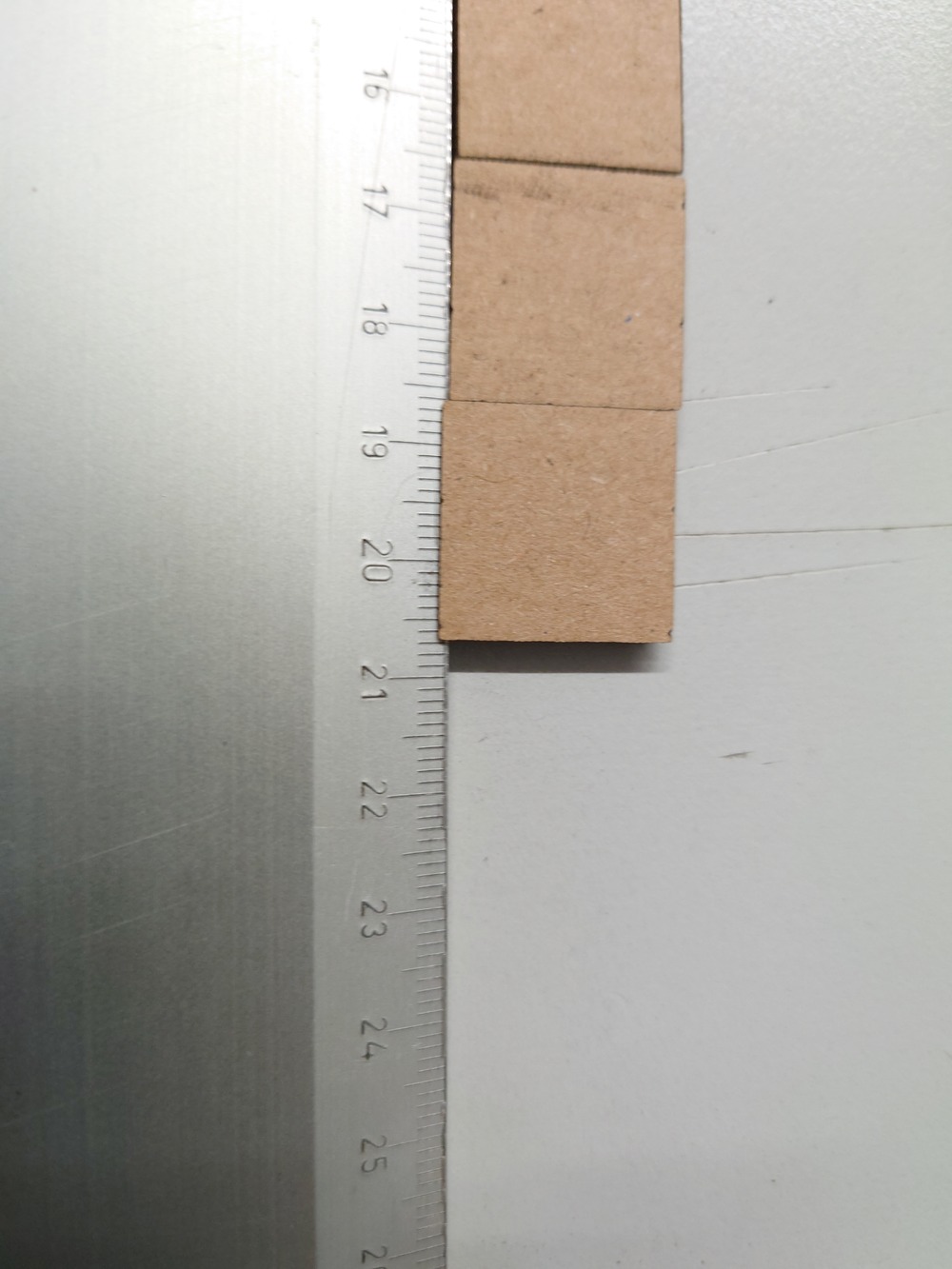
For determining the kerf, we used 10 equidistant Rectangles (e.g. 1cm) and cut them out. Now if wee look at the sides of the rectangle, because of the kerf the sides of it are reduced, all halve of the kerfs total distant. That means, if we put all squares together like shown above and measure the total length, the kerf sums up 10 times, so we can calculate the kerf with this simple equation:
(total length - expected length)/10
3.2.3.4. Joint clearance
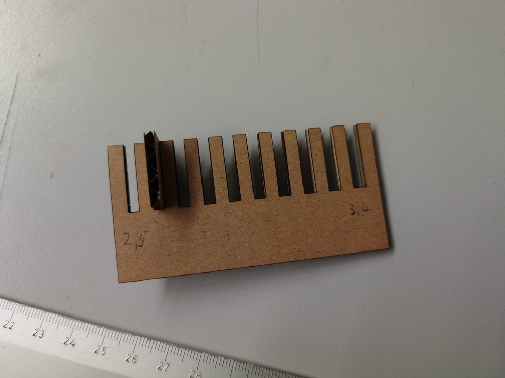
For determining the joint clearance, we used a comb-like structure with different widths around the thickness of the cardboard (in our case, 3mm). But smaller then the thickness of the cardboard is sufficient though ;D.
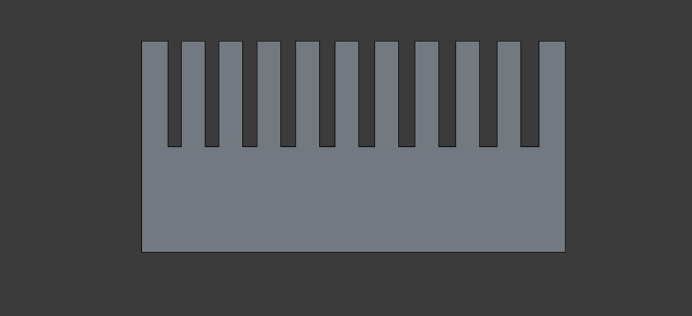
Then, after cutting, we used a piece of cardboard, clamped it in the comb and test, how good it holds/ if it goes in at all.
3.2.3.5. Speed and Power
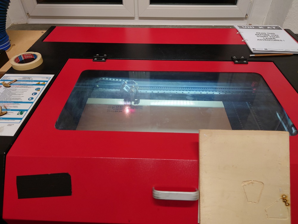
For determining the optimal speed and power configurations for cutting and engraving, we used a matrix, where each cell has a different setting for speed/power:
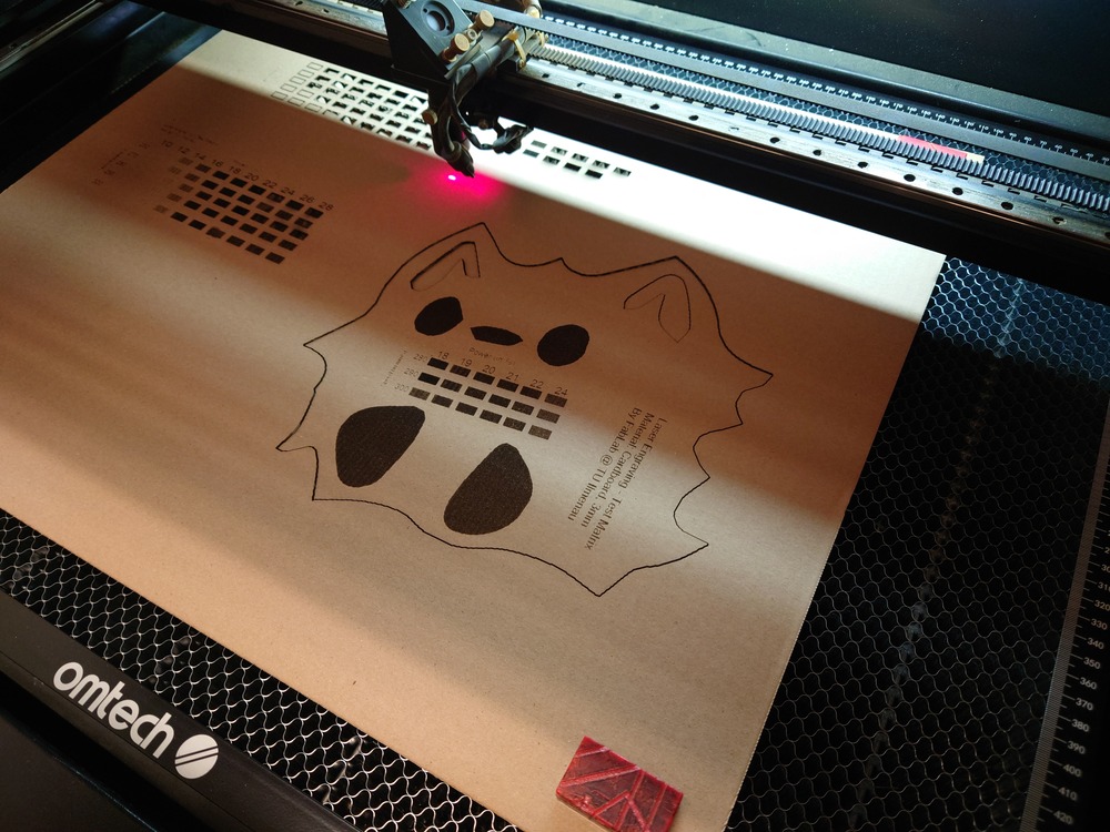
There we also found out, that over 30% power was overkill for engraving, where values lead to much smoke, and this is no good, as we learned.
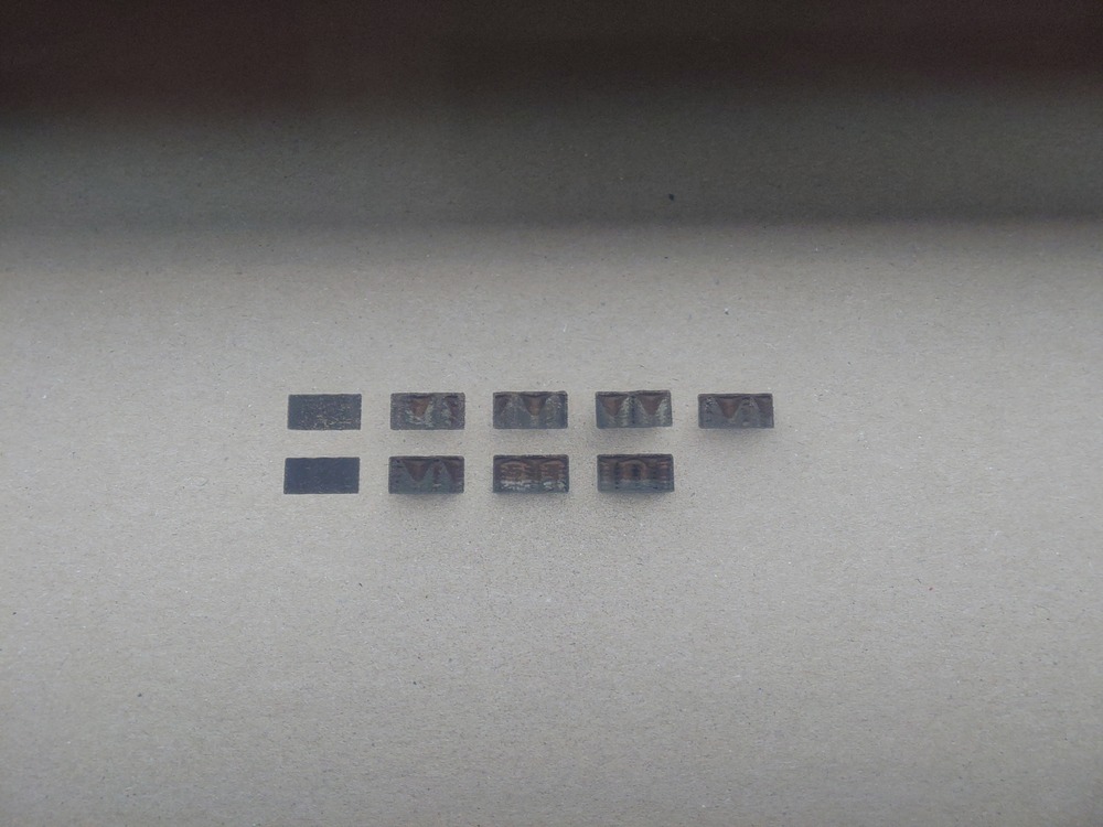
Determined Parameters
General
Kerf: 0.1mm
Joint clearance: 2.6mm
Cut:
Speed: 30mm/s
Power: 50%
Engrave (Lines):
Speed: 300mm/s
Power: 20%
Distance: 0.2mm
3.3. Individual Assignment
3.3.1. Vinyl-Cutting
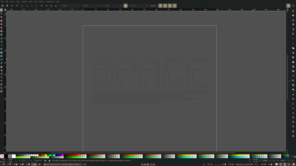
For Vinyl-Cutting I decided for the logo of our local hackspace, so I used the original image and created an outline of the font for path-creation:
Then I First tried out our CRICUT Cutter but the software used for uploading the path was so bad, that it rearranged the font completely wrong and used every path piece in the preview. I could have worked around it by handcraft it back to the original state, but I find this to be to stupid, so I used our other cutter.
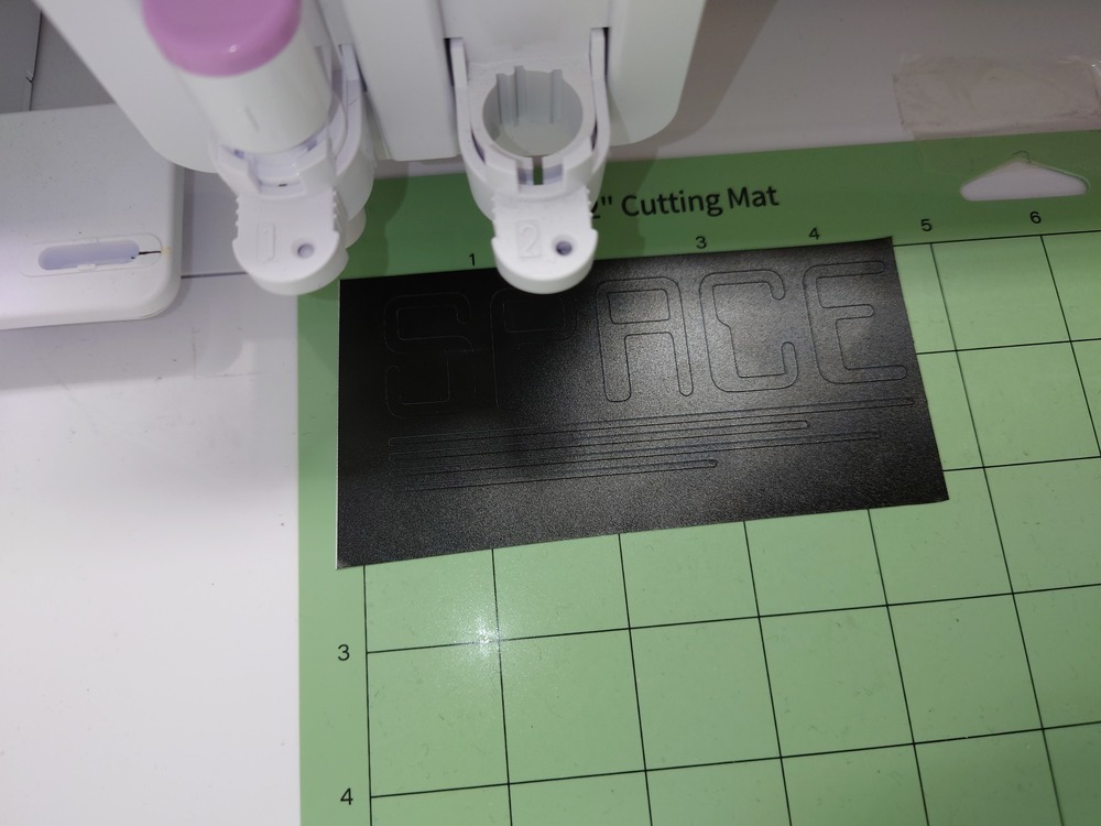
With our other cutter , the Silhouette Curio 2, there was no problem. I chose matt black for the cut, made it almost exactly the size of the print and lay it on around machine zero and started cutting:
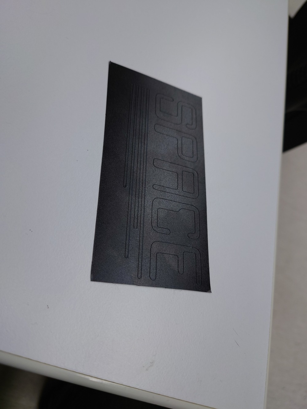
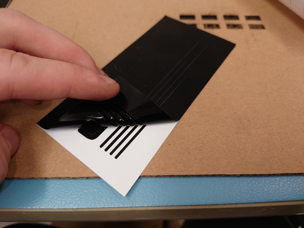
Then I removed the negative form:
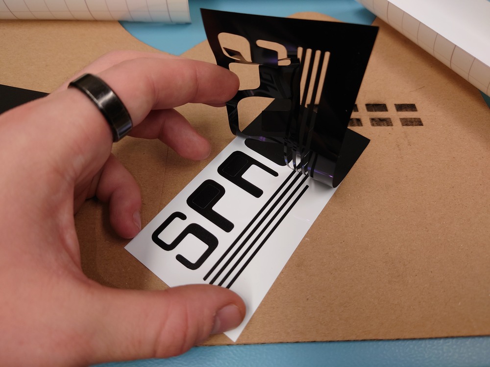
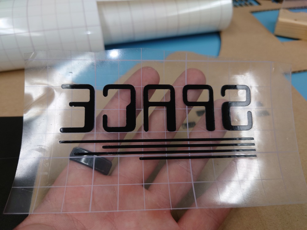
Placed the transfer film on it and pulled the logo of:
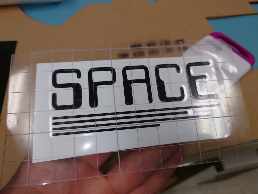
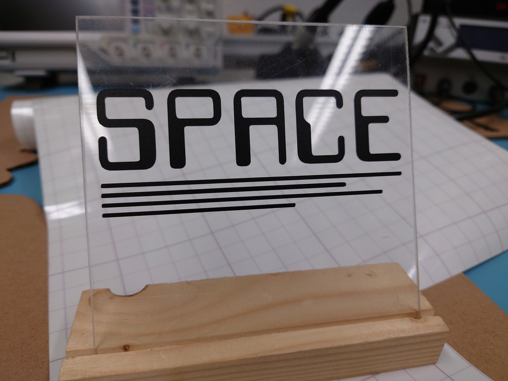
At last I just put it on a piece of acryl and have little stand:
3.3.1.1. Machine Settings

3.3.2. Laser-Cutting
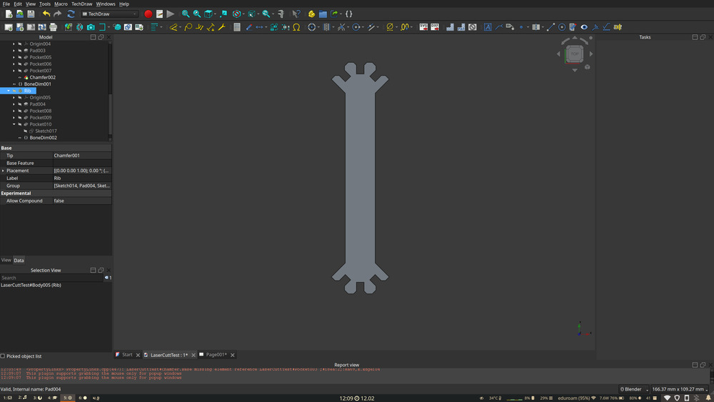
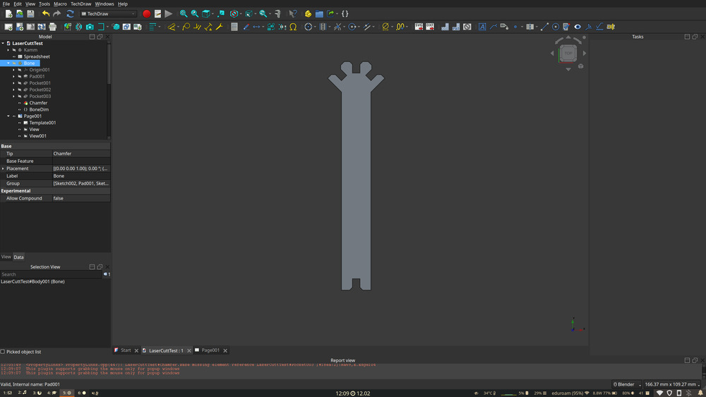
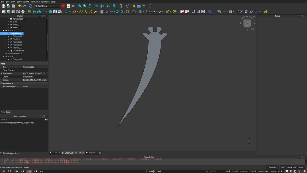
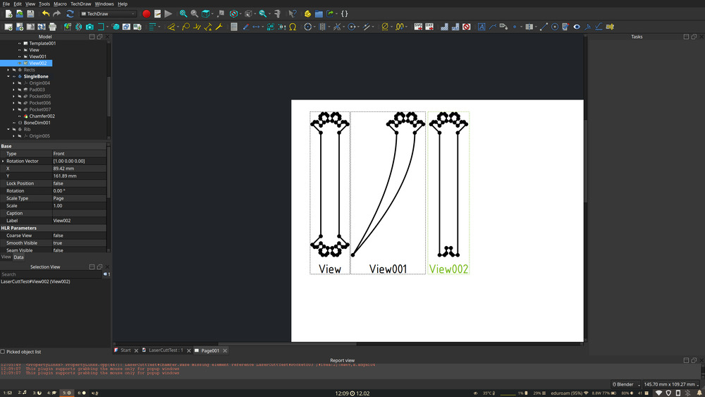
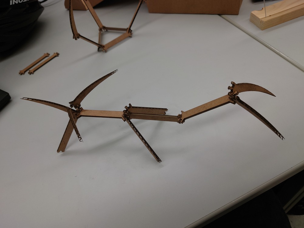
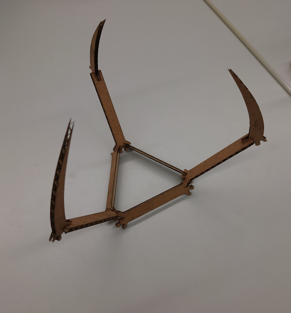
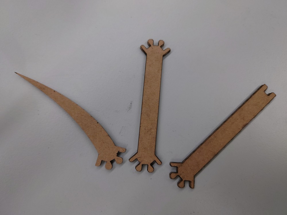
For Laser-Cutting I designed a Bone-like structure which can be used to design little skeleton-like creatures or little structures. I parametrised the length, width, the slit width and depth and for the rib the tip - distance from the center.
Different Bones
Then I used The RDWorks Software to arrange and created copies of it.
To put the cardboard on the Laser Printer, I needed to cut it to fitting pieces:
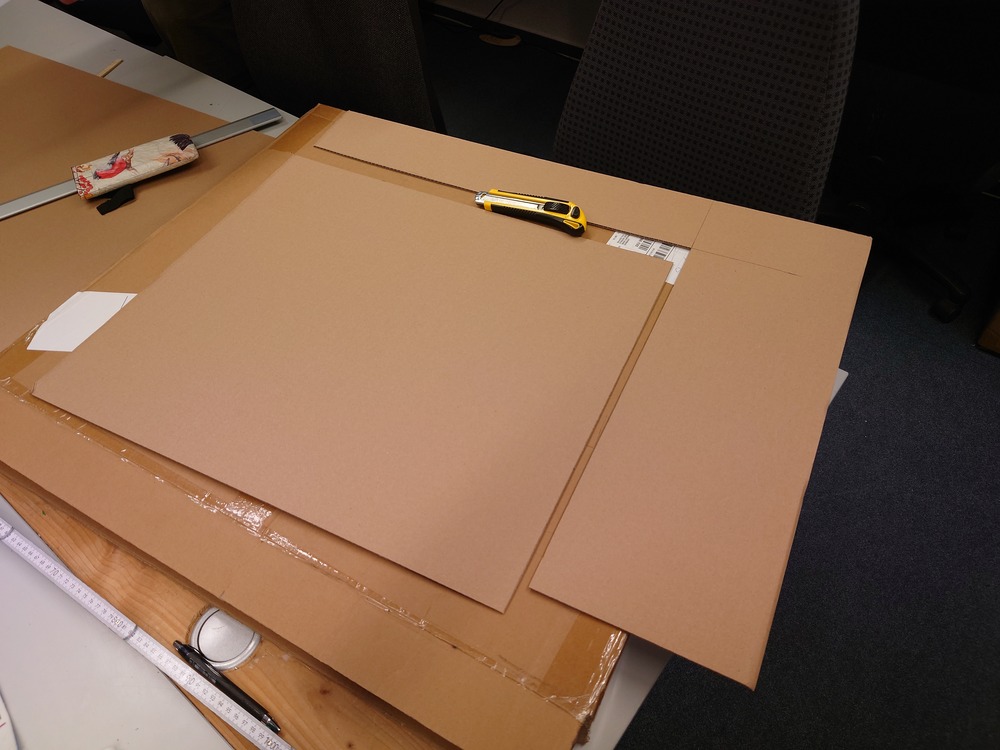
Then I uploaded the file to our Laser, chose a suitable position on the cardboard, framed it (meaning draw a bounding box around the area) to look, if it fits and started the print.

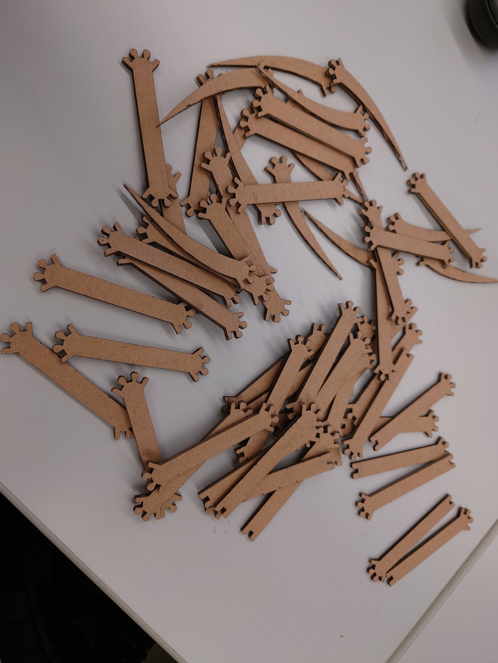
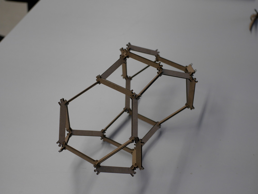
The outcome is pretty decent, but I should have designed them a little bit bigger, but should be possible with the parameters:
3.3.2.1. Machine Settings

3.3.2.2. Remarks
when uploading the file from our lokal PC connected to the lasercutter and then starting from the machine, some weird end-code happens that it want’s to drive over zero and a nasty sound comes (because he crashes into the wall)
in our case, one time the coordinate system completely changed, so zero was not in the usual spot for the machine but ist was in the middle of the plane somehow, resetting fixed it
3.4. Notes
in freecad export as .dxf -> user technical drawing and ‘insert view’
upload raw project files!
