10. Output Devices - Week 10
10.1. Assignments
Input Devices
group assignment
measure the power consumption of an output device
individual assignment
add an output device to a microcontroller board you’ve designed, and program it to do something
10.2. Group Assignment
I wanted to work with the addressable LEDs (‘NeoPixel’) for my final project, so I looked a bit more into them.
10.2.1. General about ‘NeoPixel’
Those LEDs are special because they have an Integrated Circuit (IC) for adresssing the LED, and all in a 5050 package (5mmx5mm). Addressable means in this case that the LEDs are controllable via an address via a specific protocol.
10.2.1.1. Inner Structure
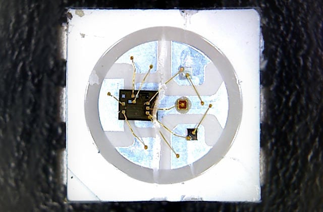
They have 4 connectors:
VCC (in this case 3-5V)
Ground (VSS)
Data Input (DIN)
Data Out (DOUT)
In the above case are the top and bottom ones VCC or Ground and connected horizontally. Then are the DIN and DOUT pins the middle ones.
10.2.1.2. How they work
To control/use them, the need a voltage and they also need to be programmed/need to have a value.
The DIN and DOUT Pins are SPI pins of the IC and receive output from another IC (e.g. the one controlling it OR another NeoPixel).
And the usual way they are used is to daisy chain the LEDs (DIN to DOUT) and only connect one DIN pin to a MCU.
That means, there is only one pin of the MCU needed to control many of those LEDs. And the amount of LED is actually only limited by your power supply and your needed frequency to change the LEDs.
This is because of how they are addressed, they use the data-in pin to receive 24 bits (3 bytes, one byte for each color). The rest is just forwarded to DOUT and the next LEDs. This way you can easily control every pixel in a stripe with only needing one wire! :D
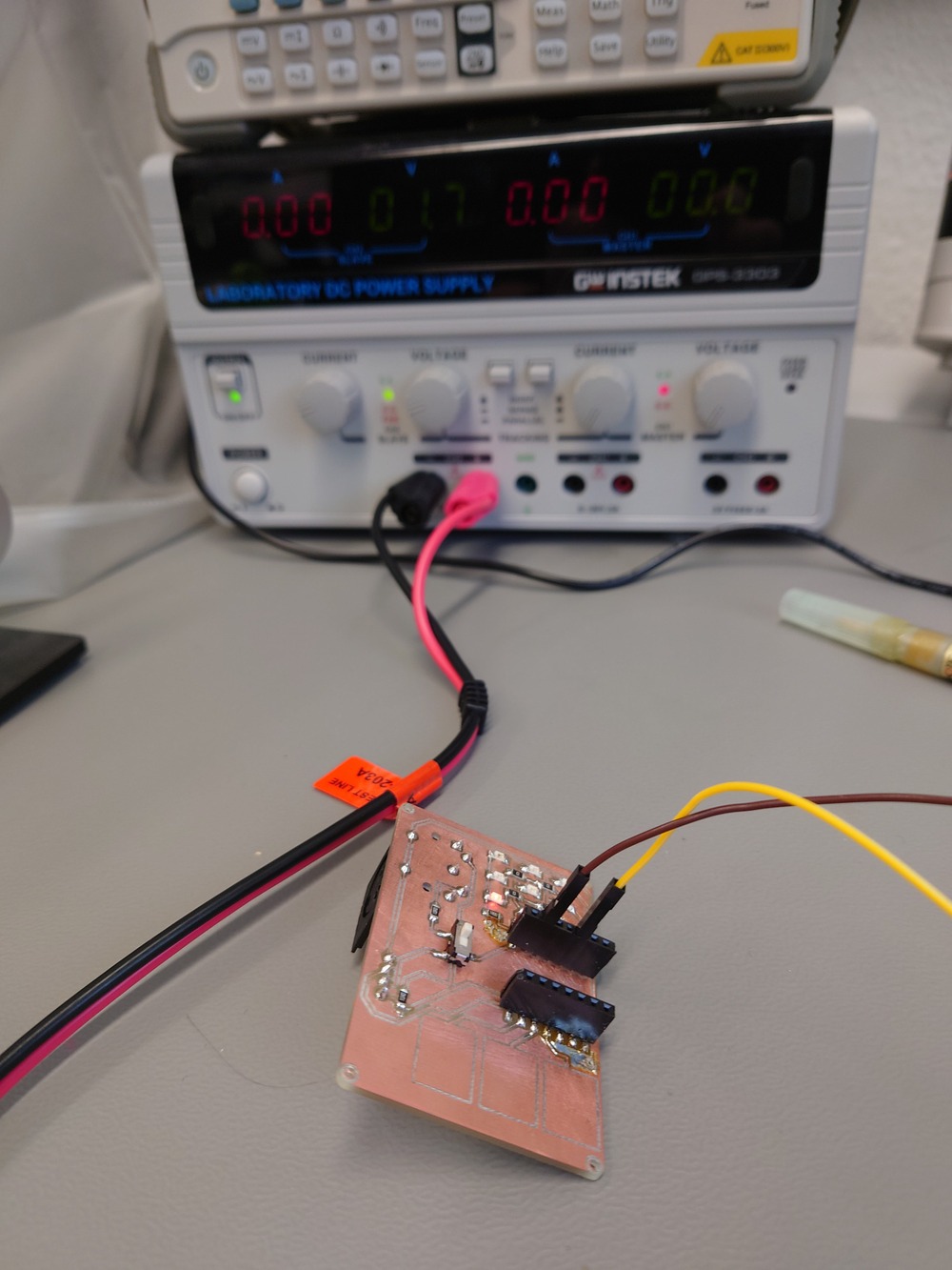
10.2.2. Measuring Power Consumption
For the Power Consumption I measured the current of one WS2812B LED to calculate, how much Ampere would run on my board below. There I limited the current to 100mA and set the Voltage to 3.3V which I wanted to operate them with in my board below. In this case, the led was used previously and pre-programmed.
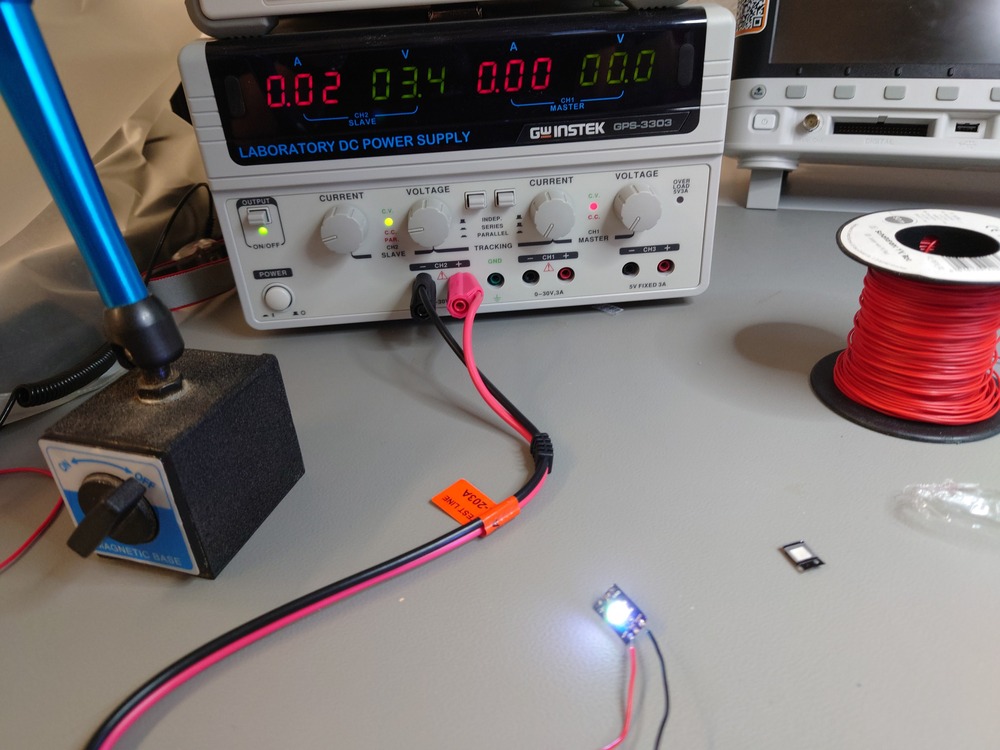
There I measured:
0.02A @ 3.3V
for one LED with color white.
I wanted to build 12 of those LEDs in my board and I wanted to use 2 of the Super Capacitors to power the board, here the energy and time calculation:
2x Super Conductors
each:
    - 10F
    - 3.8V

12x WS2812B
each:
    - 0.02A
    - 3.3V

Q = C * V = 10F * 3.8V
=> 38C == 38 As

For 1 LED:

2 * 38 As / 0.02A = 3800s == ca. 63min (-> a small pomodoro cycle :D)

For 12 LEDs:

2 * 38As / (12 * 0.02A) = 317s == ca. 5min
Also note that this is with full brightness and white color, meaning if I change to another color and decrease the brightness, I should get more time :].
10.3. Individual Assignment
10.3.1. AT Tiny412 Blink
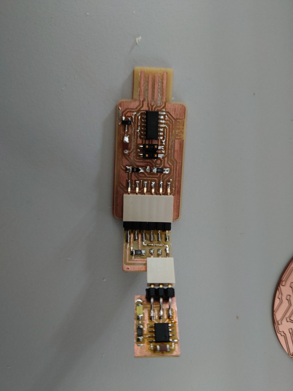
First I wanted to try out my debugger and programmer for the ATTiny412 I build in Electronic Production and just use this small and cute little board to test a simple LED Blink code without the Arduino library.
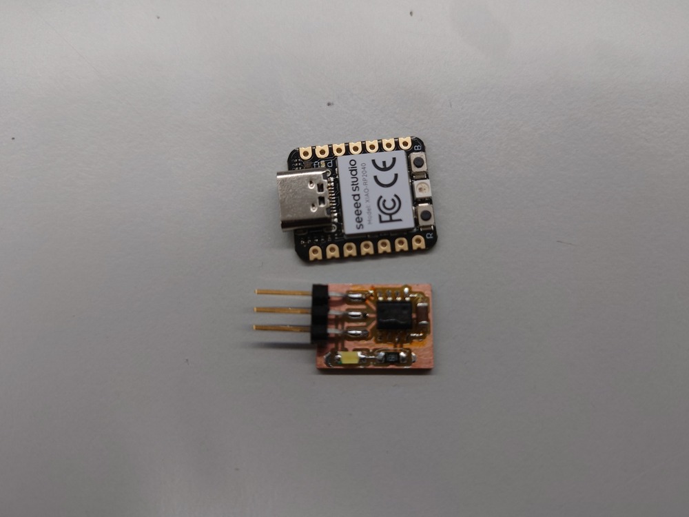
I used the FTDI Programmer and first the SPDI adapter but it didn’t work with the board because the pins are wrongly connected I guess,
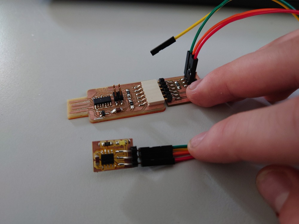
After that, I used this one which then worked with following setup.
10.3.1.1. AVR-GCC
Then I compiled this small program blink.c:
#define F_CPU 20000000ULL
#include <avr/io.h>
#include <util/delay.h>

#define PIN PIN4_bp
#define PERIOD 1000

int main(void) {
          PORTA.DIR = PIN;    // Choose pin 4 data direction
      while(1){
            PORTA.OUTSET = PIN; // set pin 4 as output pin
            _delay_ms(500);
            PORTA.OUTTGL = PIN; // Toggle state of pin 4
            _delay_ms(200);
      }
}
with following commands just with avr-gcc and avr-libc:
GCC_ARGS=(-mmcu=attiny412 -O2);
avr-gcc "${GCC_ARGS[@]}" -c blink.c -o blink.o;
avr-gcc "${GCC_ARGS[@]}" blink.o -o blink.elf;
avr-objcopy -O ihex blink.elf blink.hex
and then with my flasher-setup, I installed pymcuprog with pip and then just used:
pymcuprog  -d attiny412 -t uart -u /dev/ttyACM0 ping                    # just for checking, if the connection works
pymcuprog -d attiny412 -t uart -u /dev/ttyACM0 write -f blink.hex       # for flashing the hex file
but this didn’t work :[, I need to look into that a bit more…
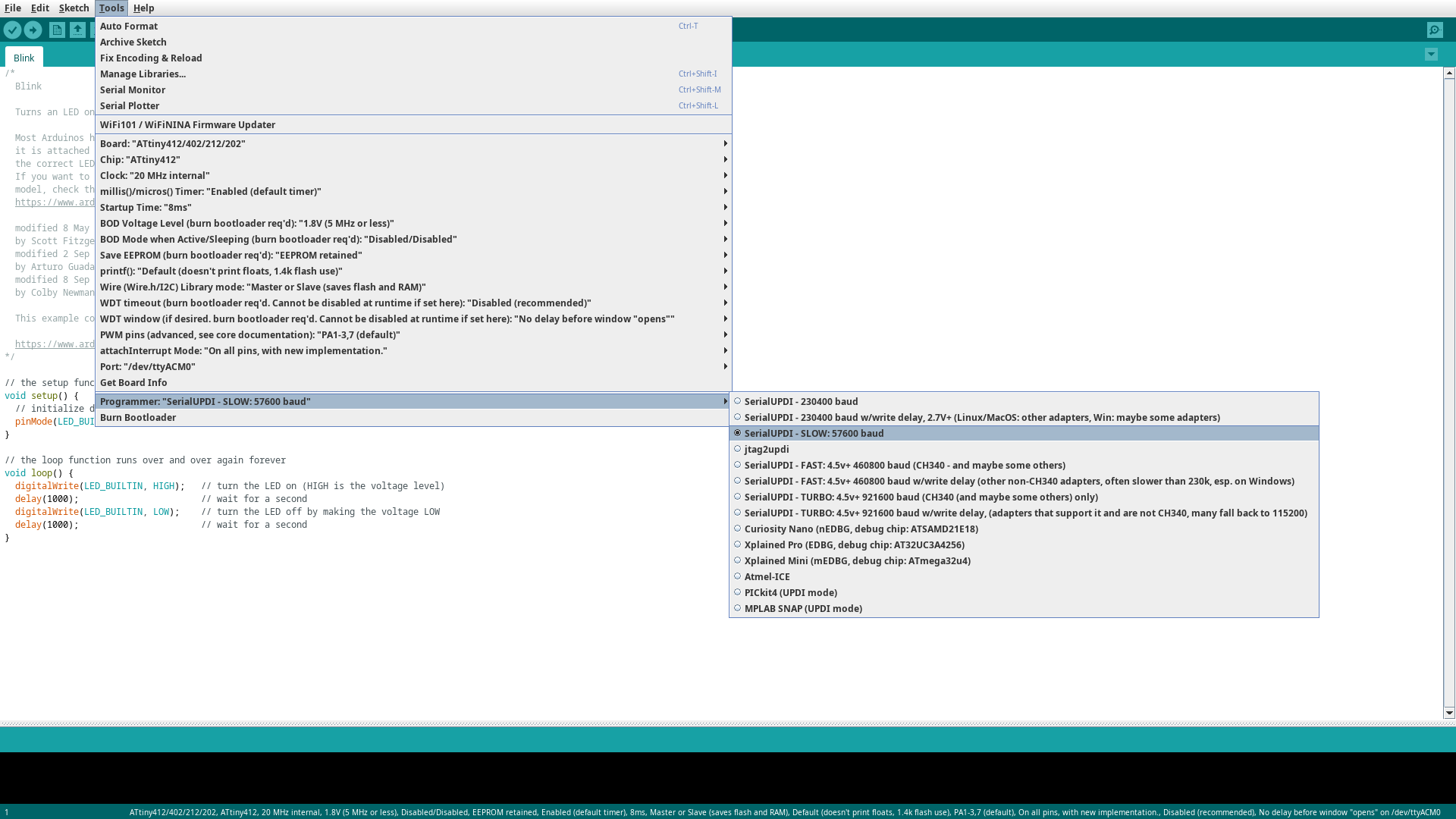
10.3.1.2. Arduino IDE
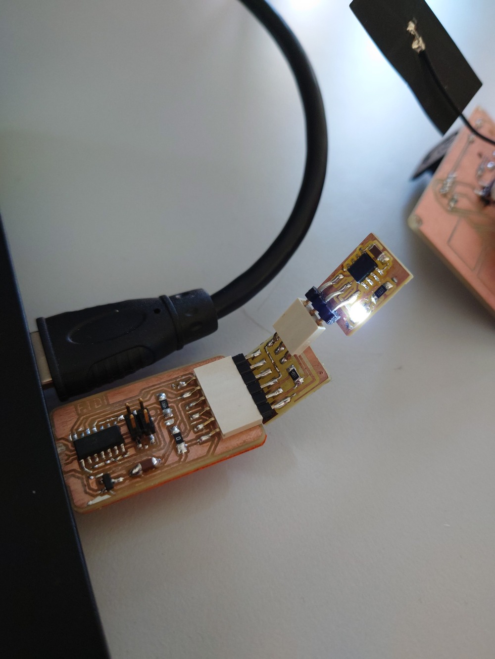
Then just as a Sanity check, I used the Arduino IDE, installed the tinyMegaCore boards and set the ATTiny412 as a target and the /dev/ttyACM0 as programmer.
Then I just loaded the blink program, and flashed it to the board
which worked :D.
10.3.2. Final Project POC
Now I used my proof of concept device from the last weeks to control the LED-Matrix with my touchpads, therefore I used the example-code for the Qtouch pins of the esp-idf. Unfortunately I did not choose the Charlieplexing for my matrix control because when I designed it, I didn’t know about such a thing.
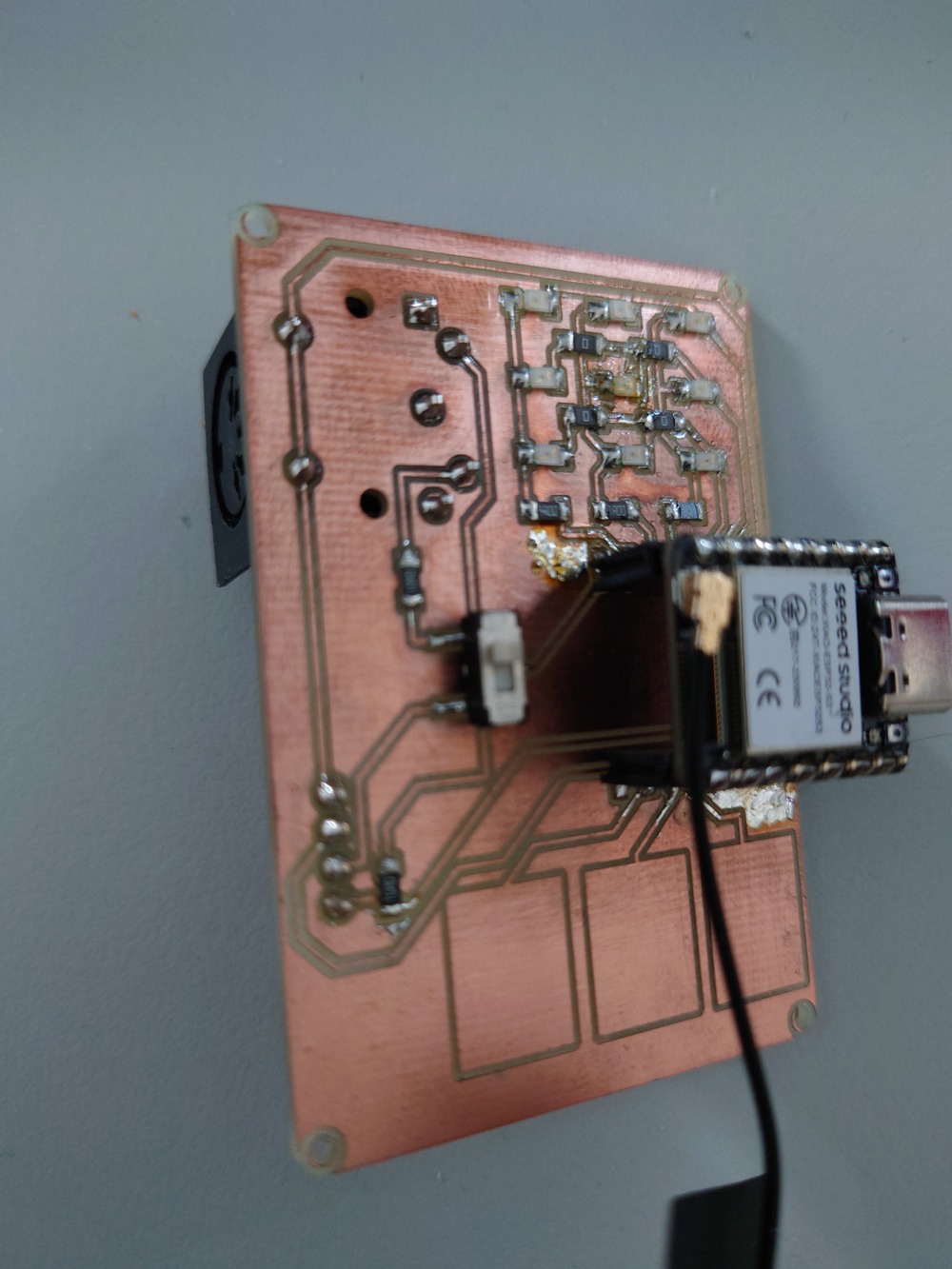
I only changed the callback for the threading-abstraction to check for the pad pressed and then blink one LED in the Matrix and some pragma-stuff.
/*
 * SPDX-FileCopyrightText: 2021-2022 Espressif Systems (Shanghai) CO LTD
 *
 * SPDX-License-Identifier: CC0-1.0
 */

#include "driver/gpio.h"
#include "driver/touch_pad.h"
#include "esp_log.h"
#include "freertos/FreeRTOS.h"
#include "freertos/task.h"
#include <inttypes.h>
#include <stdio.h>

#define TOUCH_BUTTON_NUM 3
#define TOUCH_CHANGE_CONFIG 0

#define LED_V0 1
#define LED_V1 2
#define LED_V2 3

#define LED_G0 6
#define LED_G1 5
#define LED_G2 4
static const char *TAG = "touch read";
static const touch_pad_t button[TOUCH_BUTTON_NUM] = {
    /*TOUCH_PAD_NUM1,*/
    /*TOUCH_PAD_NUM2,*/
    /*TOUCH_PAD_NUM3,*/
    /*TOUCH_PAD_NUM4,*/
    /*TOUCH_PAD_NUM5,*/
    /*TOUCH_PAD_NUM6,*/
    TOUCH_PAD_NUM7, TOUCH_PAD_NUM8, TOUCH_PAD_NUM9,
    /*TOUCH_PAD_NUM10,*/
    /*TOUCH_PAD_NUM11,*/
    /*TOUCH_PAD_NUM12,*/
    /*TOUCH_PAD_NUM13,*/
    /*TOUCH_PAD_NUM14*/
};

/*
  Read values sensed at all available touch pads.
 Print out values in a loop on a serial monitor.
 */

//
// MY CHANGES
//
static void tp_example_read_task(void *pvParameter) {
  uint32_t touch_value;

  /* Wait touch sensor init done */
  vTaskDelay(100 / portTICK_PERIOD_MS);
  printf(
      "Touch Sensor read, the output format is: \nTouchpad num:[raw data]\n\n");

  while (1) {
    for (int i = 0; i < TOUCH_BUTTON_NUM; i++) {
      touch_pad_read_raw_data(button[i], &touch_value); // read raw data.
      printf("T%d: [%4" PRIu32 "] ", button[i], touch_value);
      if (i == 0) {
        if (touch_value > 30000) {
          gpio_set_level(LED_V1, 1);
        } else {
          gpio_set_level(LED_V1, 0);
        }
      }
      if (i == 1) {
        if (touch_value > 30000) {
          gpio_set_level(LED_V2, 1);
        } else {
          gpio_set_level(LED_V2, 0);
        }
      }
      if (i == 2) {
        if (touch_value > 30000) {
          gpio_set_level(LED_V0, 1);
        } else {
          gpio_set_level(LED_V0, 0);
        }
      }
    }
    printf("\n");
    vTaskDelay(200 / portTICK_PERIOD_MS);
  }
}

//
// END MY CHANGES
//

void app_main(void) {
  /* Initialize touch pad peripheral. */
  touch_pad_init();
  for (int i = 0; i < TOUCH_BUTTON_NUM; i++) {
    touch_pad_config(button[i]);
  }
  gpio_reset_pin(LED_V0);
  gpio_reset_pin(LED_V1);
  gpio_reset_pin(LED_V2);
  gpio_reset_pin(LED_G0);
  gpio_reset_pin(LED_G1);
  gpio_reset_pin(LED_G2);
  /* Set the GPIO as a push/pull output */
  gpio_set_direction(LED_V0, GPIO_MODE_OUTPUT);
  gpio_set_direction(LED_V1, GPIO_MODE_OUTPUT);
  gpio_set_direction(LED_V2, GPIO_MODE_OUTPUT);
  gpio_set_direction(LED_G0, GPIO_MODE_OUTPUT);
  gpio_set_direction(LED_G1, GPIO_MODE_OUTPUT);
  gpio_set_direction(LED_G2, GPIO_MODE_OUTPUT);
  gpio_set_level(LED_G0, 0);
  gpio_set_level(LED_G1, 1);
  gpio_set_level(LED_G2, 1);
#if TOUCH_CHANGE_CONFIG
  /* If you want change the touch sensor default setting, please write
   * here(after initialize). There are examples: */
  touch_pad_set_measurement_interval(TOUCH_PAD_SLEEP_CYCLE_DEFAULT);
  touch_pad_set_charge_discharge_times(TOUCH_PAD_MEASURE_CYCLE_DEFAULT);
  touch_pad_set_voltage(TOUCH_PAD_HIGH_VOLTAGE_THRESHOLD,
                        TOUCH_PAD_LOW_VOLTAGE_THRESHOLD,
                        TOUCH_PAD_ATTEN_VOLTAGE_THRESHOLD);
  touch_pad_set_idle_channel_connect(TOUCH_PAD_IDLE_CH_CONNECT_DEFAULT);
  for (int i = 0; i < TOUCH_BUTTON_NUM; i++) {
    touch_pad_set_cnt_mode(button[i], TOUCH_PAD_SLOPE_DEFAULT,
                           TOUCH_PAD_TIE_OPT_DEFAULT);
  }
#endif
  /* Denoise setting at TouchSensor 0. */
  touch_pad_denoise_t denoise = {
      /* The bits to be cancelled are determined according to the noise level.
       */
      .grade = TOUCH_PAD_DENOISE_BIT4,
      .cap_level = TOUCH_PAD_DENOISE_CAP_L4,
  };
  touch_pad_denoise_set_config(&denoise);
  touch_pad_denoise_enable();
  ESP_LOGI(TAG, "Denoise function init");

  /* Enable touch sensor clock. Work mode is "timer trigger". */
  touch_pad_set_fsm_mode(TOUCH_FSM_MODE_TIMER);
  touch_pad_fsm_start();

  /* Start task to read values by pads. */
  xTaskCreate(&tp_example_read_task, "touch_pad_read_task", 4096, NULL, 5,
              NULL);
}
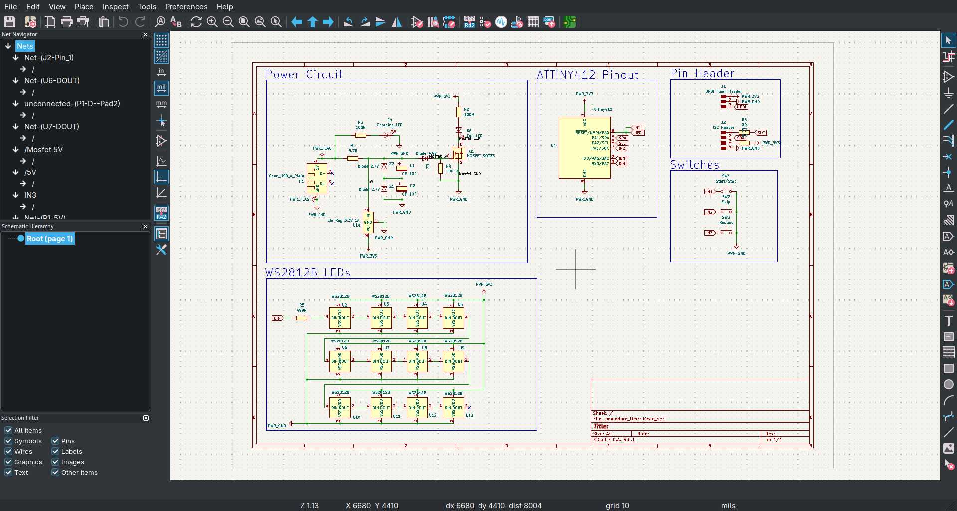
There I first mixed the pin-direction up in my schematics, where I then tested the LEDs manual:
But then I corrected the code and it worked :D
Also I tested out the NeoPixel LEDs in the next week.
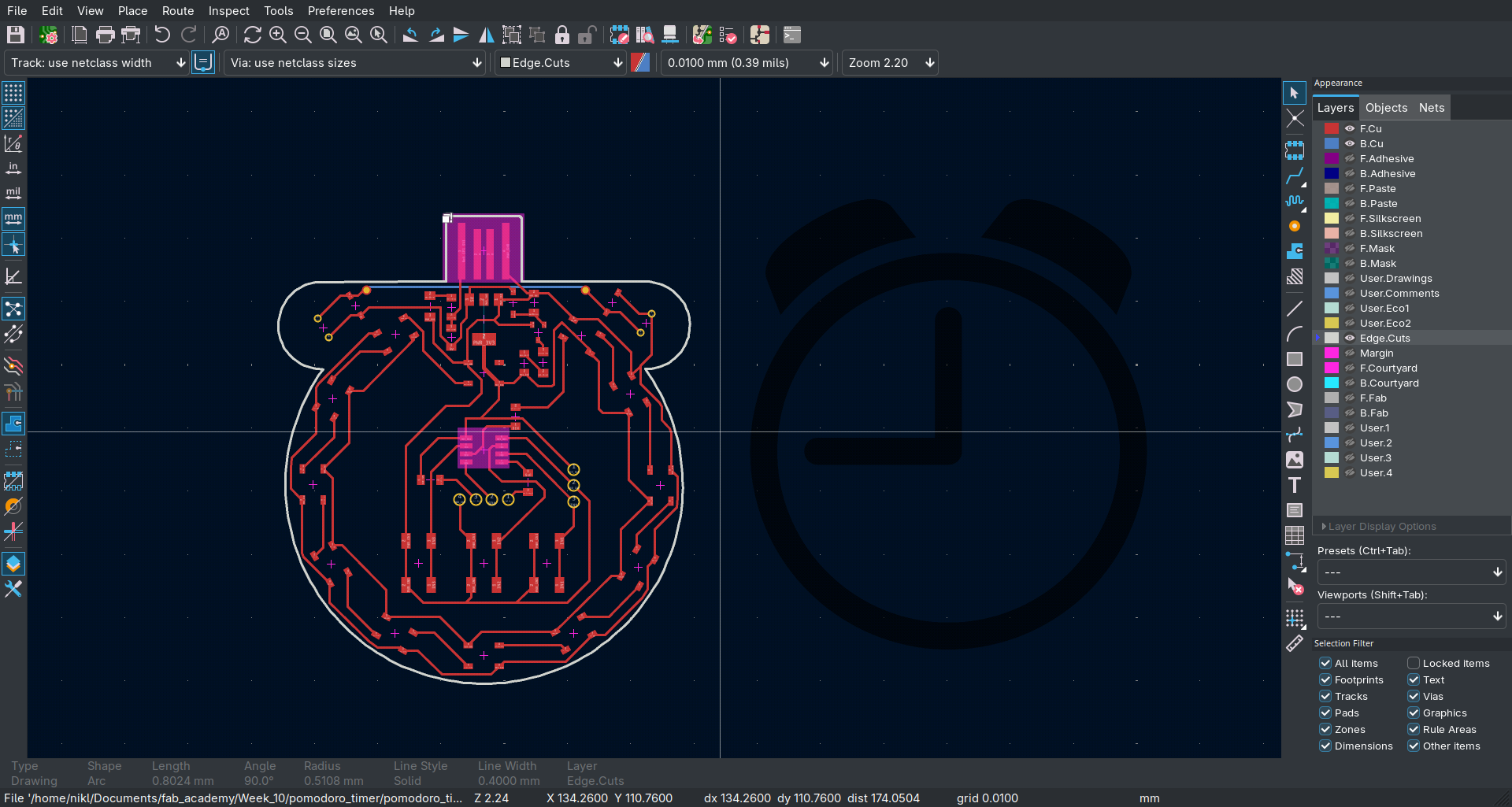
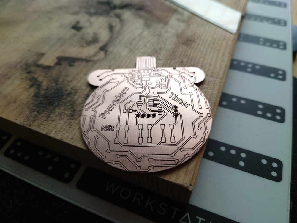
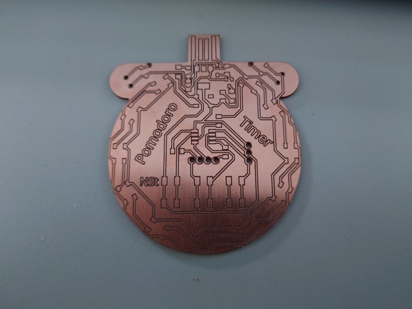
10.3.3. Pomodoro Timer
10.4. Notes
https://gcc.gnu.org/wiki/avr-gcc