9. Input Devices - Week 9
9.1. Assignments
Input Devices
group assignment
probe an input device’s analog levels and digital signals
individual assignment
measure something: add a sensor to a microcontroller board that you have designed and read it
9.2. Group Assignment
For the Group assignment I tested a Step Response Signal.
9.2.1. General
A Step Response Sensor uses a Heaviside-Signal (the ‘Step’-Signal) on some system to get the ‘Response’ of this individual system. (the mathematical base for this type of sensor comes from control-theory) A system in our case is e.g.: air, fingre, foam, etc.
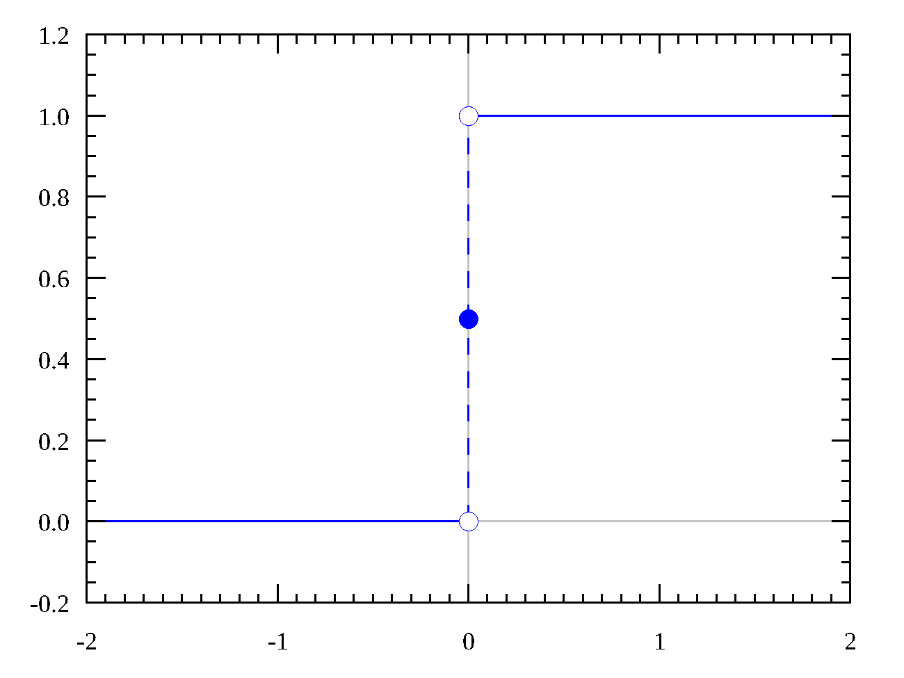
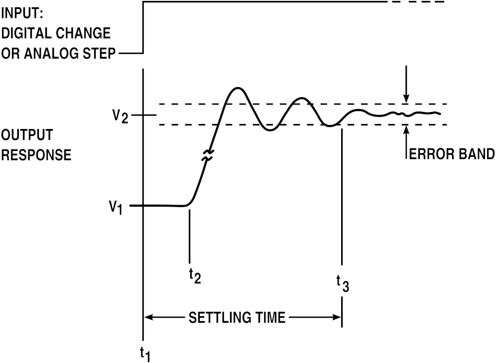
Response of a general system to a step signal.
First it should in some kind increase the output of the system up to a maximum value (because of the constant input to it)/overshoots the actual maximum and then this should slowly ‘settle’ (decrease to a stable value) to the expected value, and this in a ‘ringing’-way (decrease-increase cycle).
(Source)
This response heavily depends on the ‘system’ the signal is applied to which changes the ‘charge-up-time’, ‘charge-up-speed’ and maximum of the response.
Electrically this means that the sensor uses the environment as a capacitor which is charged up and measured.
And for measuring this with a microcontroller there are 2 implementation: Using one ore two input-pins.
In the first setup, the ground from the environment is used and the pin building the electrical field is also used as the measuring pin.
In the second setup, sending and receiving is separated, so that there is always common ground and the change in the electrical field is measured.
The steps inside the sensors breaks down to following:
Create the step signal by charging up an output pin on a microcontroller (setting the pin to high)
this actually creates a capacitor with the microcontroller and the environment around it acting as the system
This then also charges up the environment this pin is in contact with because of the electrical filed created by setting the pin high.
Then in the simplest setup with one pin, the pin changes to an input-pin and now measures the decrease of the charged-up environment.
or another pin is used for measuring, here the change in the electrical field is measured
The measurement loop begins again on 1.
And this is done extremely quick (as quick as possible)
Usually the pins are extended with ‘plates’ used for the electrical field, where sensitivity depends on the size of the plates.
This can then be used as a sensor for many things because of this general step-response principle, e.g.: resistance, capacitance, inductance, position, pressure, tilt, acceleration, humidity, proximity, touch, multitouch, force, bending, …
9.2.2. Probing QTouch
I tested QTouch which uses the already integrated hardware for measuring touches using a finite-state machine. (Application Note)
Device Out-/Input
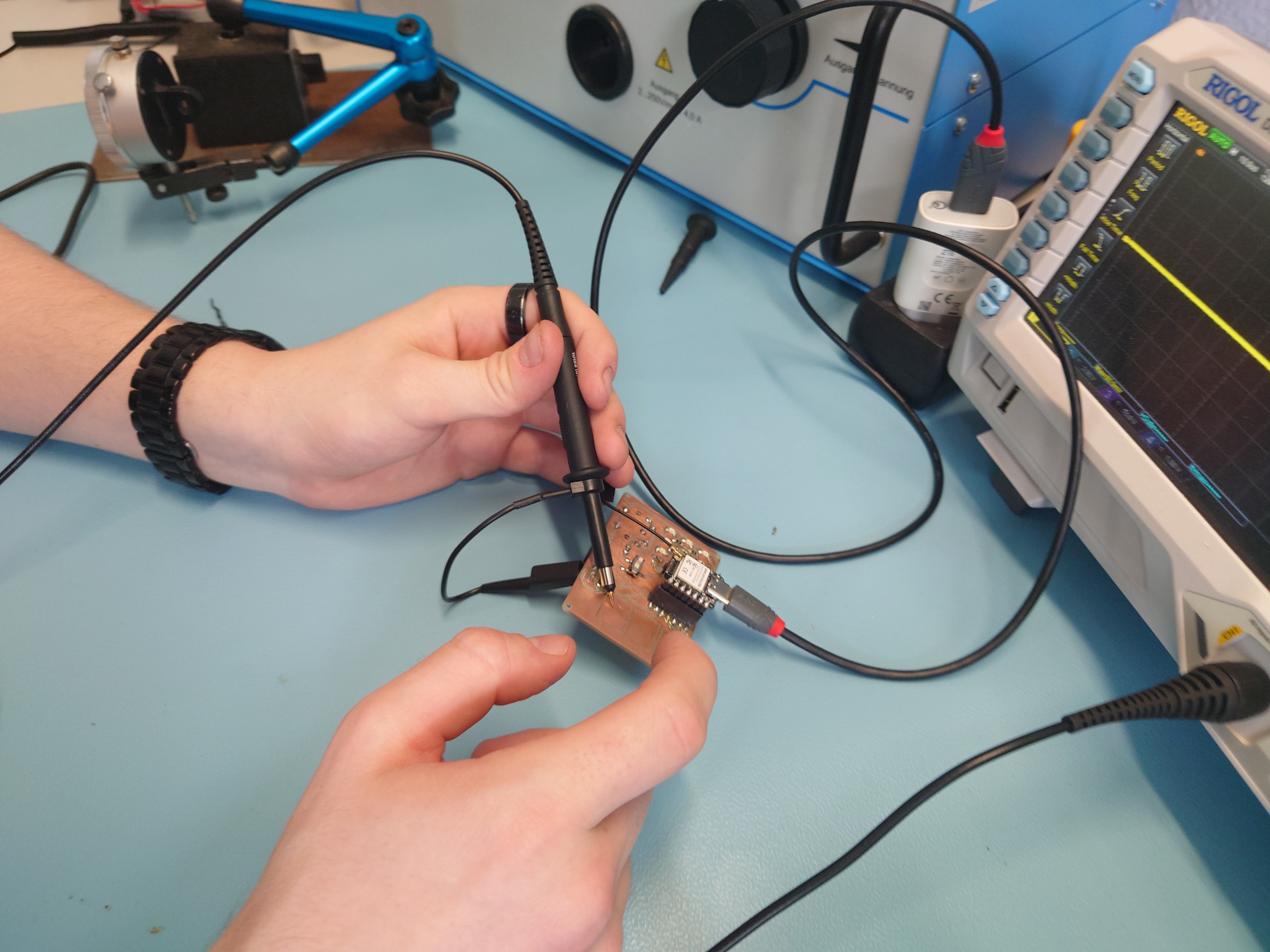
Here I measured the send out signal, I put ground on the board-ground and measured the output signal (step-signal) of the touch-pad.
As you can seen above the closer the finger gets to the touch pad, the longer it takes to settle down. Also here you can see the overlaying signal from the finger and the fast send step from the touch-library (when the oscilloscope can’t trigger), I think.
Self Capacitance
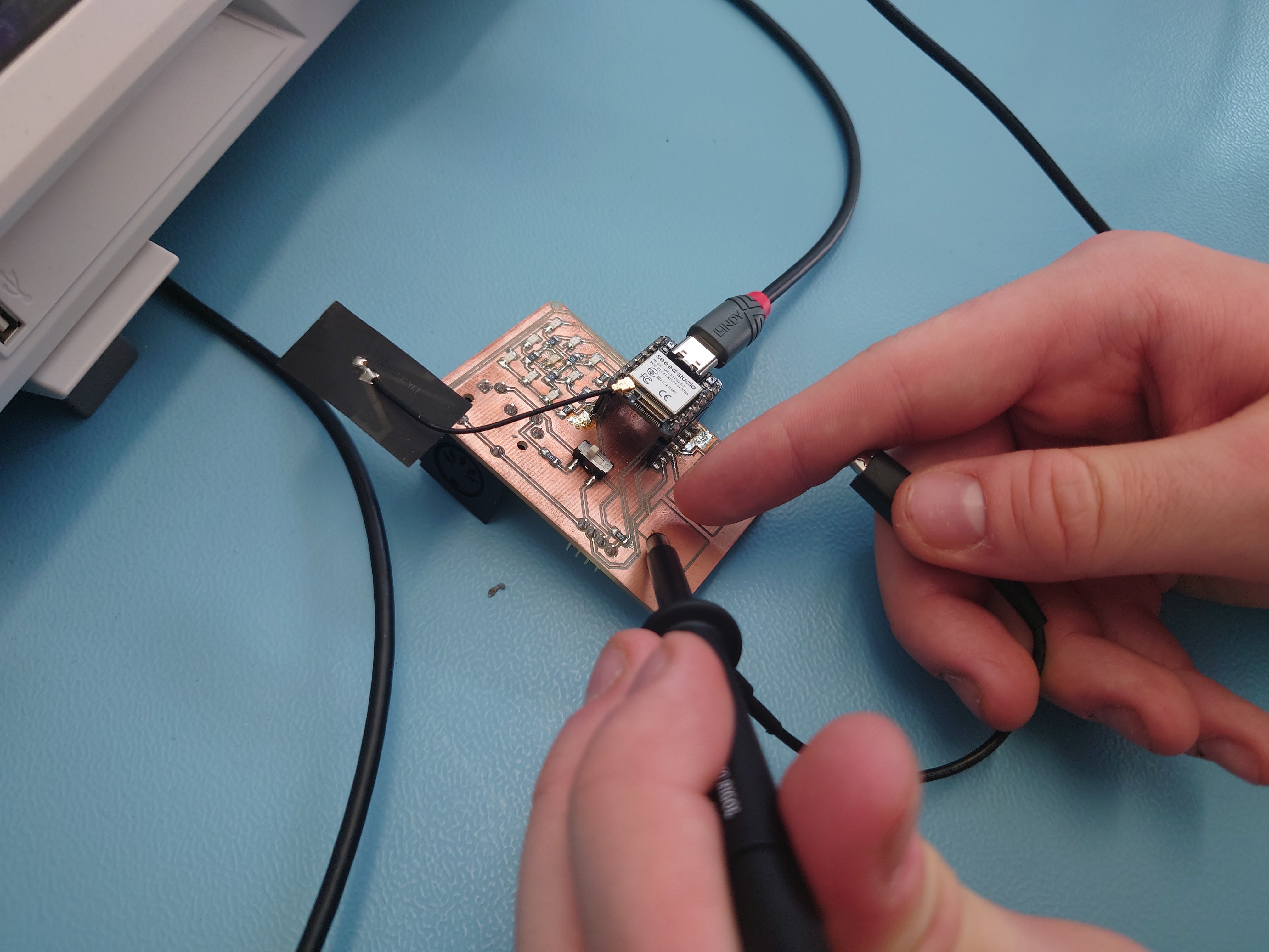
Here I measured the capacitance of me by using my finger as ground and measuring the touchpad.
Here you can see the charge-up and release clearly indicating a capacitor and also the closer I get the change in capacitance.
The code used on the esp32 is down below.
9.3. Individual Assignment
I used my previously milled board to test the step response with QTouch and print it out on the serial connection.
As the base, I used this example as base for the code:
#include "driver/touch_pad.h"
#include "esp_log.h"
#include "freertos/FreeRTOS.h"
#include "freertos/task.h"
#include <inttypes.h>
#include <stdio.h>

#define TOUCH_BUTTON_NUM 3
#define TOUCH_CHANGE_CONFIG 0

static const char *TAG = "touch read";
// touch pad pins I used
static const touch_pad_t button[TOUCH_BUTTON_NUM] = {
    TOUCH_PAD_NUM7,
    TOUCH_PAD_NUM8,
    TOUCH_PAD_NUM9,
};

/*
  Read values sensed at touch pads.
 Print out values in a loop on a serial monitor.
 */
static void tp_example_read_task(void *pvParameter) {
      uint32_t touch_value;

      /* Wait touch sensor init done */
      vTaskDelay(100 / portTICK_PERIOD_MS);
  printf(
          "Touch Sensor read, the output format is: \nTouchpad num:[raw data]\n\n");

  while (1) {
    for (int i = 0; i < TOUCH_BUTTON_NUM; i++) {
               touch_pad_read_raw_data(button[i], &touch_value); // read raw data.
      printf("T%d: [%4" PRIu32 "] ", button[i], touch_value);
    }
    printf("\n");
    vTaskDelay(200 / portTICK_PERIOD_MS);
  }
}

void app_main(void) {
  /* Initialize touch pad peripheral. */
  touch_pad_init();
  for (int i = 0; i < TOUCH_BUTTON_NUM; i++) {
           touch_pad_config(button[i]);
  }
  /* Denoise setting at TouchSensor 0. */
      touch_pad_denoise_t denoise = {
      /* The bits to be cancelled are determined according to the noise level.
       */
      .grade = TOUCH_PAD_DENOISE_BIT4,
      .cap_level = TOUCH_PAD_DENOISE_CAP_L4,
  };
  touch_pad_denoise_set_config(&denoise);
  touch_pad_denoise_enable();
  ESP_LOGI(TAG, "Denoise function init");

  /* Enable touch sensor clock. Work mode is "timer trigger". */
  touch_pad_set_fsm_mode(TOUCH_FSM_MODE_TIMER);
  touch_pad_fsm_start();

  /* Start task to read values by pads. */
  xTaskCreate(&tp_example_read_task, "touch_pad_read_task", 4096, NULL, 5,
                                NULL);
}
Then build and flash:
idf.py set-target esp32s3
idf.py -p /dev/ttyACM0 flash
And it works. Initially I had a problem with this being very slow, but this was because of the STACK SIZE set for the task in FreeRTOS, so made the stack 4x the size before:
//                                                        ____ this was 1024 before
xTaskCreate(&tp_example_read_task, "touch_pad_read_task", 4096, NULL, 5, NULL);
And then it was very stable.