7. Computer-Controlled Machining - Week 7
7.1. Assignment
Computer-Controlled Machining
group assignment
do your lab’s safety training
test runout, alignment, fixturing, speeds, feeds, materials,
and toolpaths for your machine
individual assignment
make (design+mill+assemble) something big (~meter-scale)
extra credit: don’t use fasteners or glue
extra credit: include curved surfaces
7.2. Group Assignment
7.2.1. CNC Machines
In our lab, we have following:
7.2.2. Safety training
always look for/hear the mill
FIRE!!
keep flex low -> longer milling mill sticks out, more flex -> as short as possible, as long as necessary (flute length)
keep a distance and safety gear!!
hair, weary cloth -> 20k RPM of mill -> HURTS BAD
stuff (work-piece, chips, MILLS!) flies away -> especially mill -> carbide -> hard -> kick-back -> work-piece throw
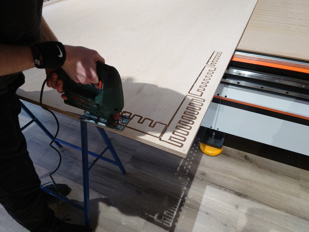
no gloves!!
7.2.3. Machine Properties and Parameters
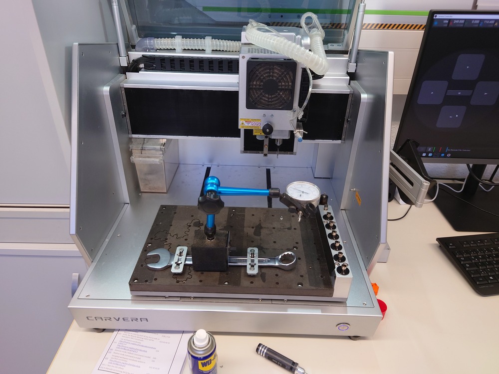
We used the Carvera in our Lab to learn about those parameters and test them out, because this is the one we will use the most.
7.2.3.1. Conventional(CW) vs Climb-Cut(CCW)
Conventional : Movement direction of the workpiece and rotation direction of the mill are opposite.
Consequences:
not that good edges but the machine does not need to be that stiff
Climb-Cut : Movement direction of the workpiece and rotation direction of the mill are the same.
Consequences:
good edged but machine needs to be stiff
much force needed for cuts
7.2.3.2. Run-Out
Run-Out : The movement the Drill/Mill does around its rotation axis, which is never perfectly concentric.
Measuring
Using a dial-indicator we clamped on something rigid:
we gently touched the mill with it
set the scale to zero
and rotated the mill and looked in the changes of distance
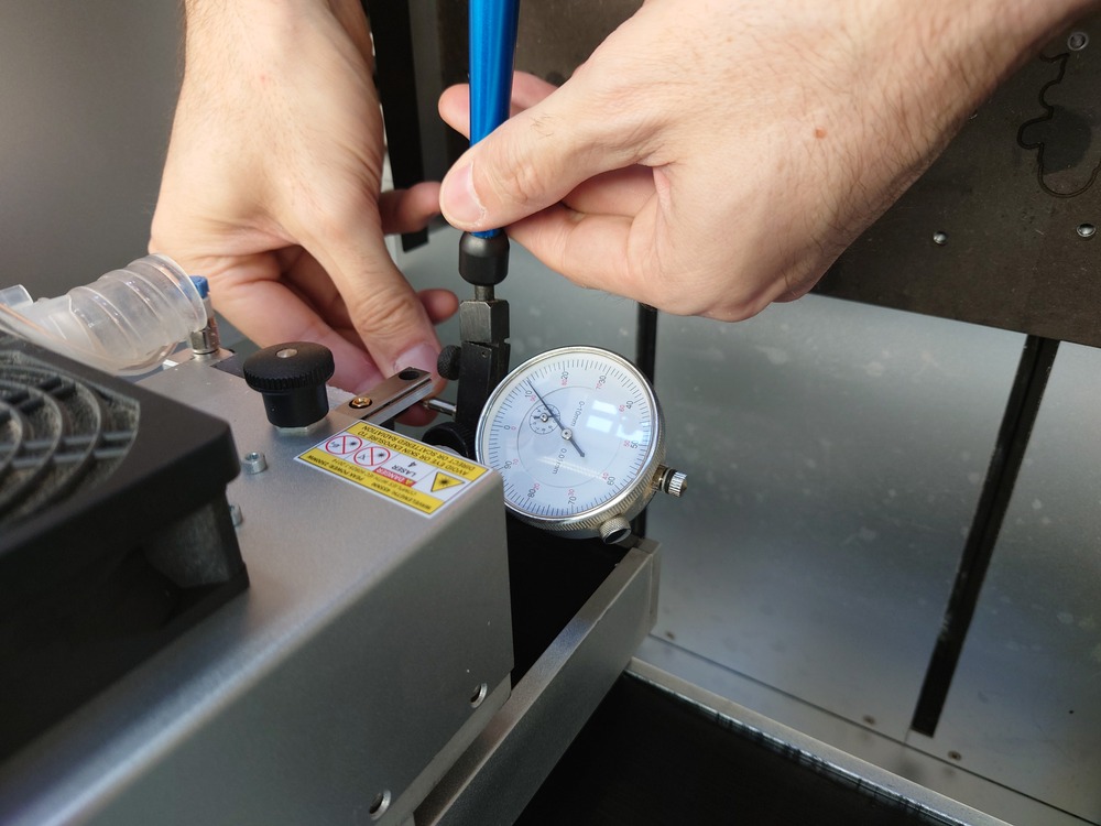
Outcome
In our Case, event at the tip of the machine, we couldn’t measure a real distance. The distance we measured were just errors resulting from a not stiff mounting
7.2.3.3. Alignment
Following 2 Properties are important:
Steps per mm
Meaning in the distance given in my G-Code should be the same as the actual distance the CNC travels.
Measuring
Just move in all available axis a distance and measure the actual traveled.
G1 X0 Y100
G1 X100 Y0
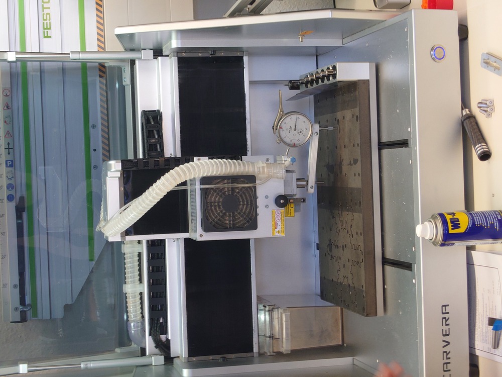
Perpendicularity to bed
The mill should be perpendicular to the bed for optimal milling results, but in reality, there is always a little angle between mill and bed.
Measuring
For a rough measure, use a right angle. Better: Attach an dial-indicator on the Z-Axes (Mill-axes) and drive around the bed and if the needle does not move, it is very perpendicular
7.2.3.4. Fixturing
Fixturing the workpiece is very important because of the possibly strong force that acts on it.
Possible Methods:
Clamps (T-slot, Nuts, Mitee-Bite)
think about overlapping!!
avoid using!!
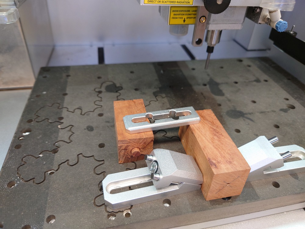
Screws (better)
Vacuum Table (good for 2 sided milling)
Tape (see Electronics Production Week)
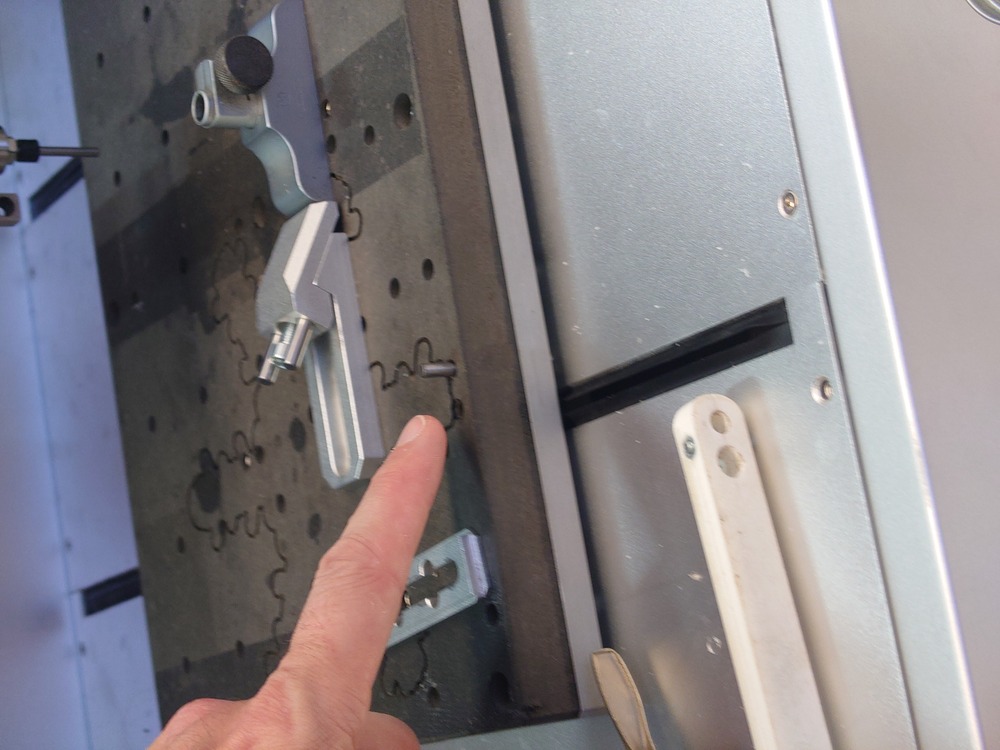
Also for positioning Alignment Bits are very useful, because they are measured in and guarantee, that the workpiece is in the right orientation.
7.2.3.5. Speeds and Feeds
Very dependent on the material and used mill. Should be determined with LISTENING.
Feed-Rate : Movement of the mill cutting in the material
should not be to high -> resulting in the translative force into the material to be to high -> moving it
should not be to low -> more friction of the mill and material -> burning/melting
Speed/RPM of Mill
not to slow -> increase in translative force resulting in the movement of the workpiece
not to high -> increase of friction resulting in burn/melt
How to find the optimal Speeds and Feeds
Use the machine defaults and test it with the mill on the material and LISTEN
If it melts/burns:
stop, clean
turn RPM down
manually step, if chips are produced, good
use reasonable feed-rate
Look at the chips and adjust the speeds accordingly
increasing the feed-rate (same RPM) results in longer chips
increasing the RPM (same feed-rate) results in shorter chips
Chips should be in a reasonable length and the machine should not sound horrifying
chips should be:
not too short -> material gets pushed more then chips are produced -> high rubbing -> short chips stick to the mill
not too long -> chips get tangled in the mill -> no good
7.2.3.6. Up-cut vs Down-cut Bit
up-cut : Flute direction like a drill, resulting in an upwards movement
Consequences:
gets chips out but no clean edge
down-cut : Flute direction opposite to a drill, resulting in a downwards movement
Consequences:
pulls chips down but clean edge
cross-cut : does both (split in flut direction), on the tip up-cut and down-cut on the rest of the flute, but usually more expensive
7.2.3.7. Step-down and Step-over
Step-down : Different depth-steps into the material to not mill the whole workpiece in once
usually the diameter of the mill
Step-over : The radius/diameter the mill is moved into the material/overlaps with the last path
7.2.4. Milling the Fixture Test Comb
I use Freecad for modelling and also for milling with the Carvera, and Fusion for the CNC from CNC-Multitool.
7.2.4.1. Makera Carvera Desktop
G-code generation
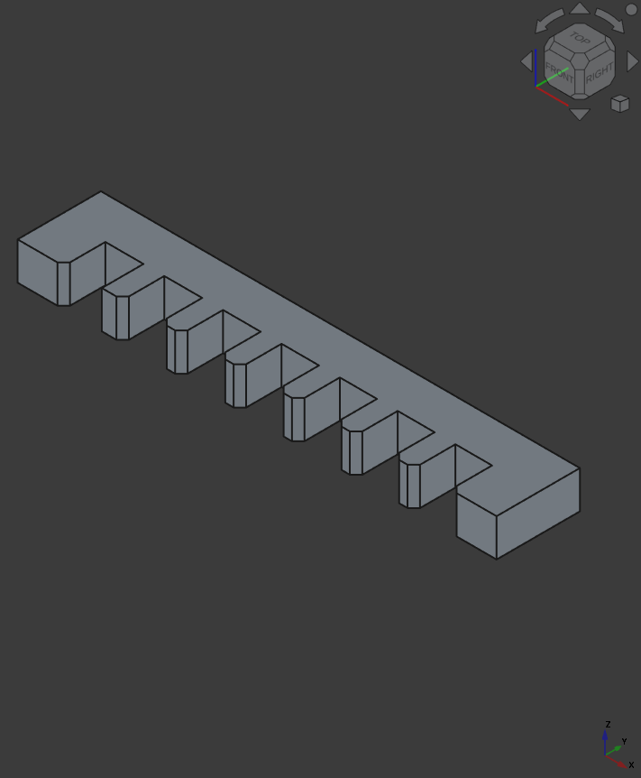
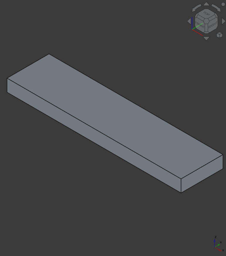
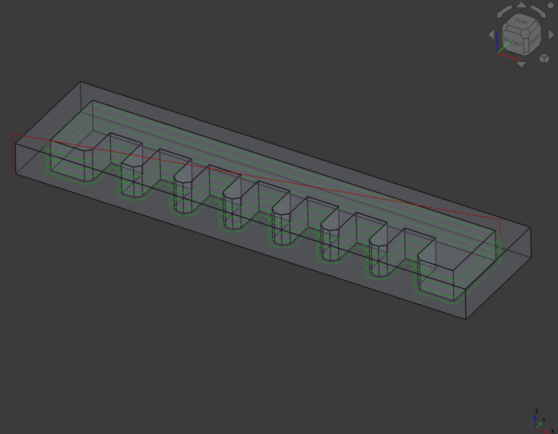
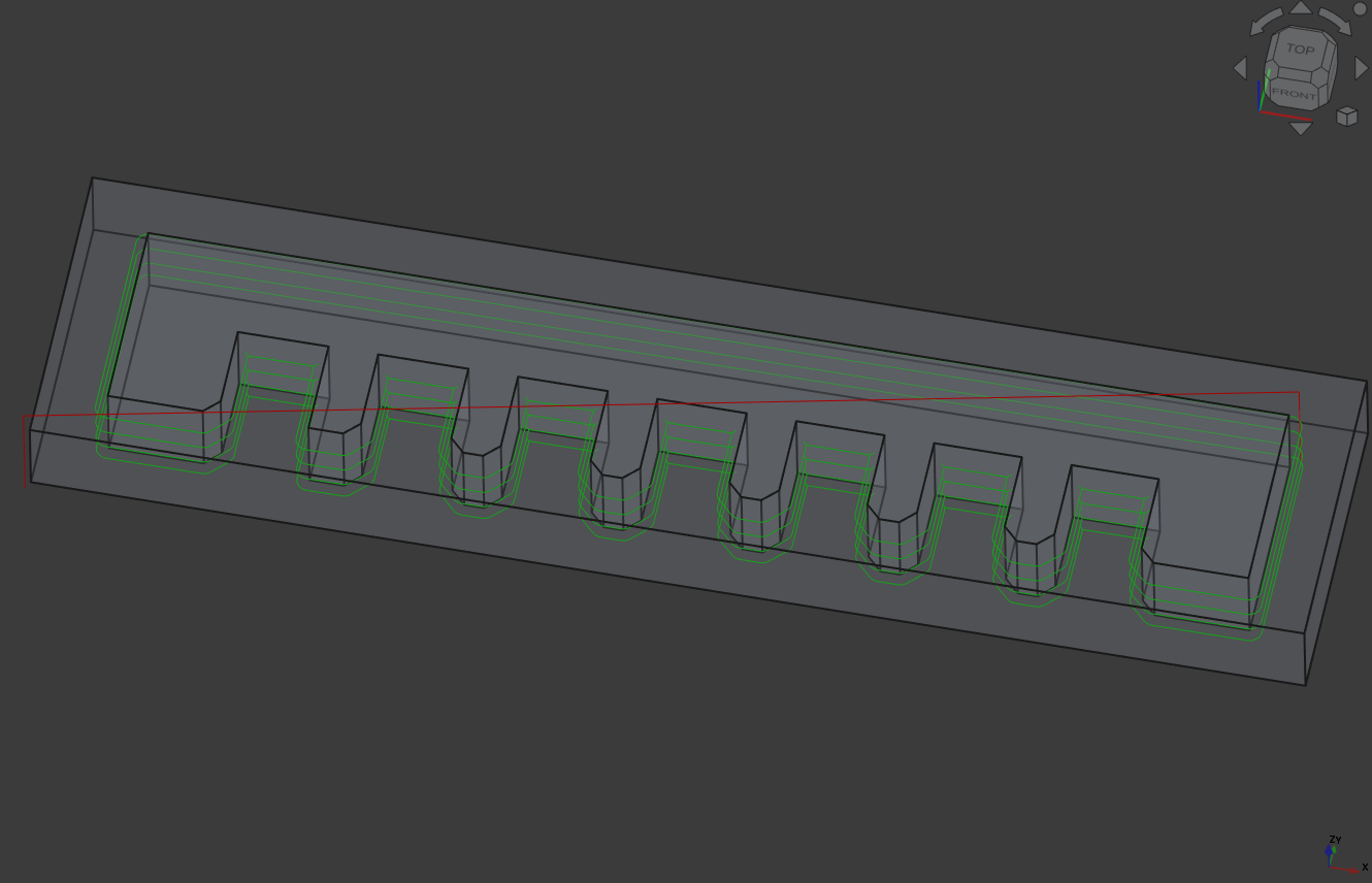
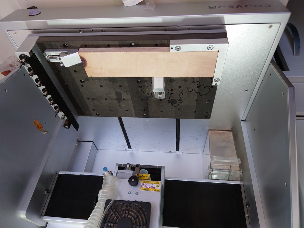
For our Test-wood (15mm depth) I designed a small comb with distances between 14.9mm and 14.4mm in a 0.1mm difference (I forgot to add 15mm and also values above -.- but in the end it was the right scale for this wood). Also I also modeled the workpiece to use as stock for the job. We tested the real wood on the bigger CNC.
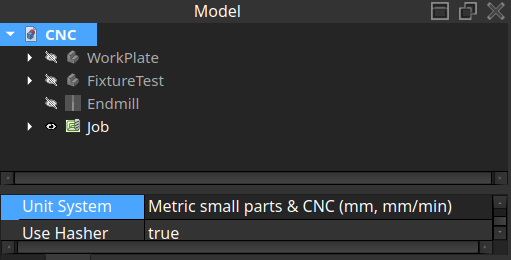
Then to create a path, I first changed the units of the Project (and in general) to mm/min (for the RPM).
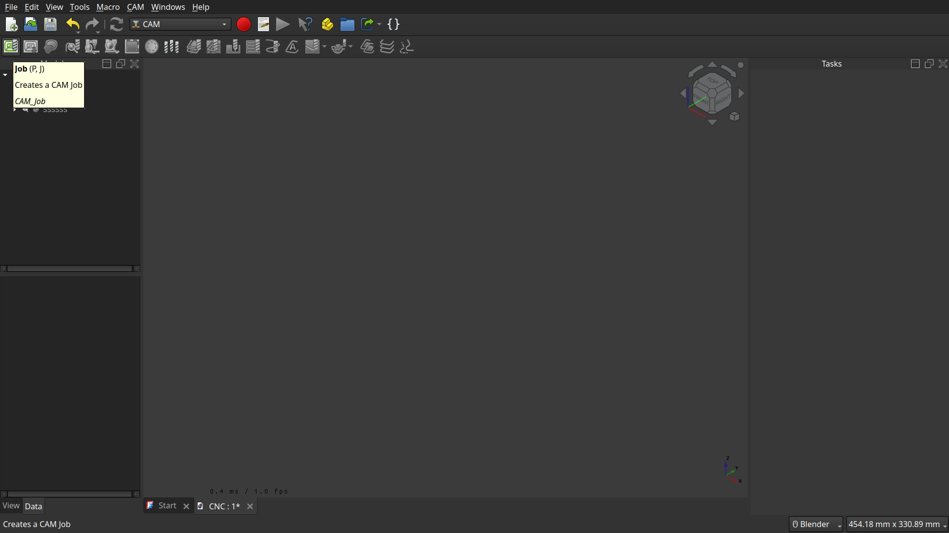
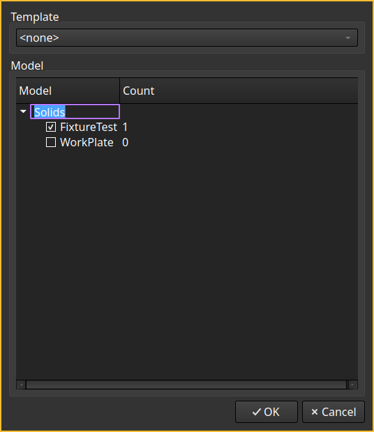
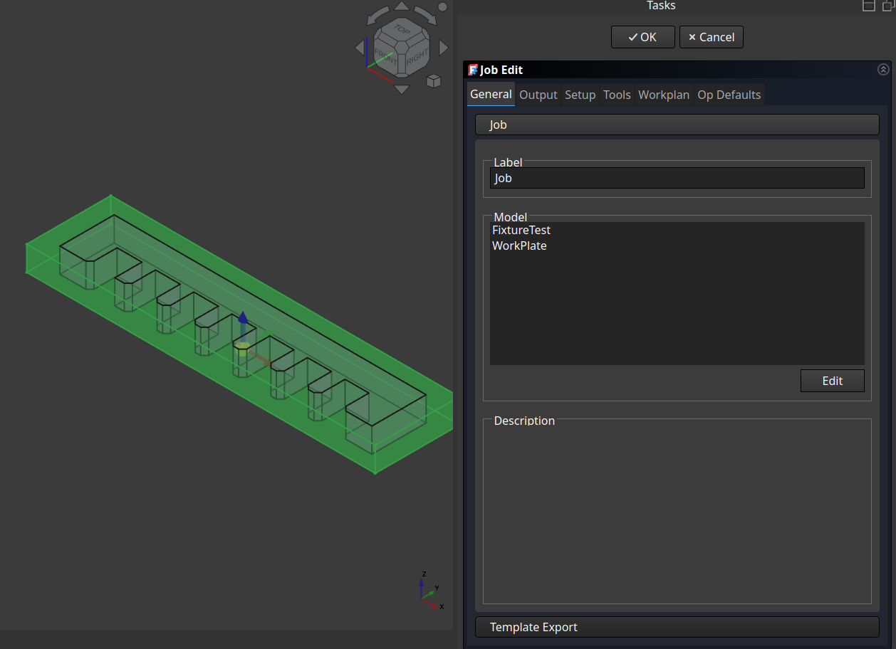
Then I switched to the CAM Workspace and started a job and added the models to it:
In the ‘Output’-Tab I first set the processor to mach3,mach4, which is needed for our Carvera.
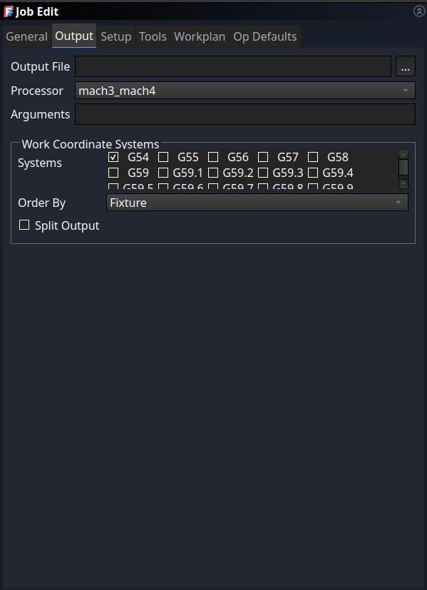
Next in the ‘Setup’-Tab I selected my workpiece as stock (‘existing solid’) and chose the bottom-left corner as the origin (in the ‘Alignment’-Section).
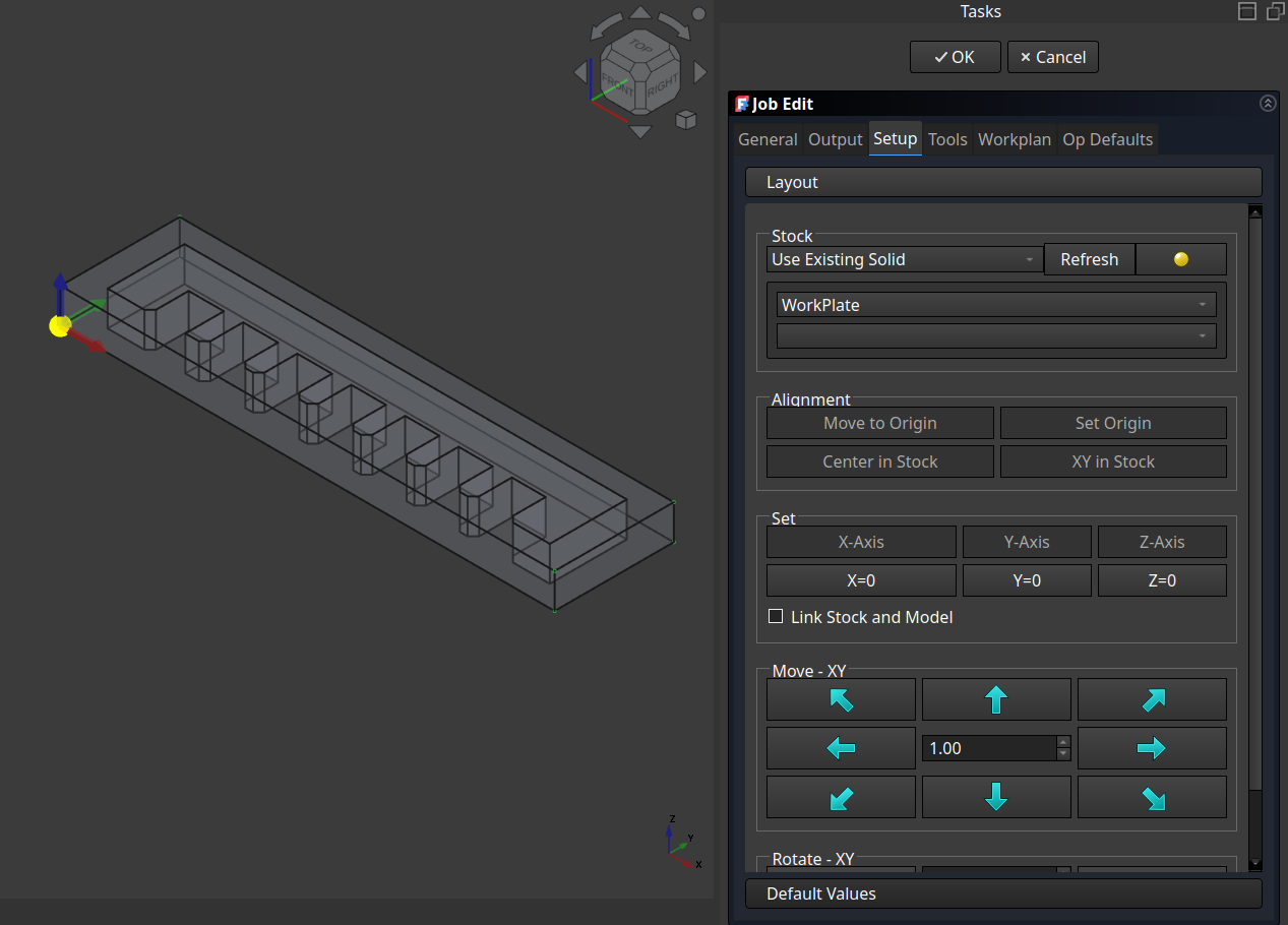
Note
It is also possible to use just a ‘bounding box’, I used that at the CNC from a friend of mine.
Also for the later images I used the ‘Extend Models Bounding Box’-Stock accidentally (the black lines around the stock), so don’t mind those lines.
Also important but can be done later is to create and adjust the used tool.
Go to the tool library
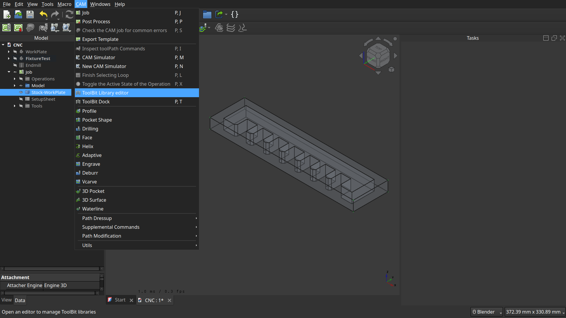
Here go to ‘Create Toolbit’
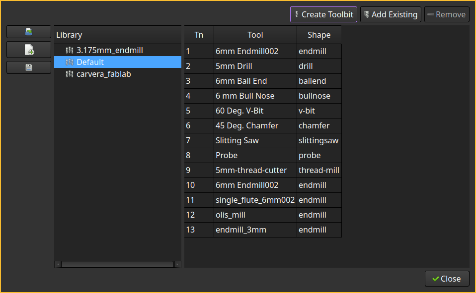
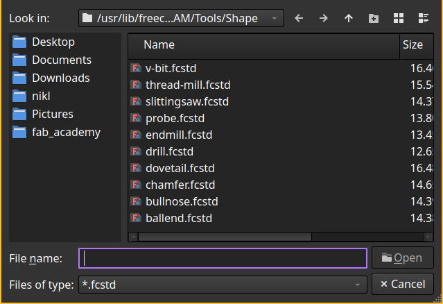
Choose the Tool Shape
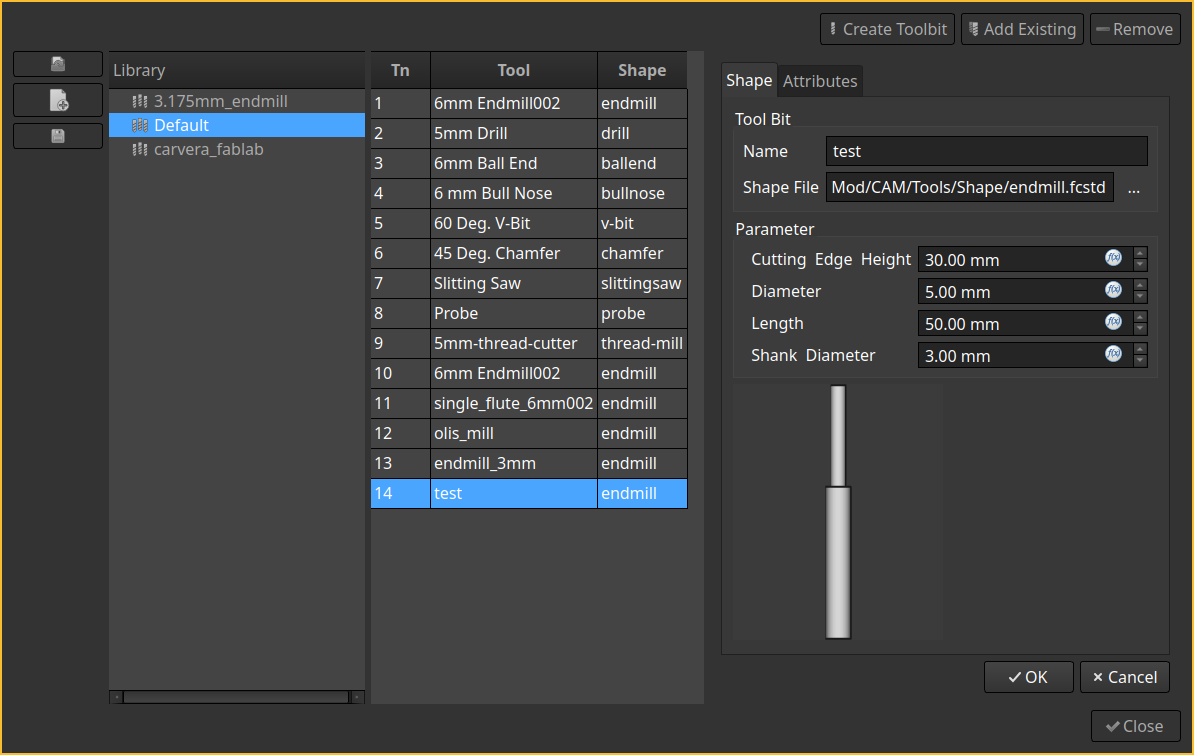
And adjust the settings
There you need to set all distances and flute number of the tool (‘Attribues’ Tab).
And then add the tool to the job:
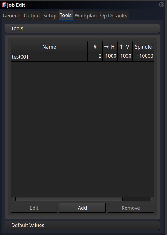
Important
Also important is to set the Speed (Spindel RPM) and Freed (H(orizontal) and V(ertical)) there!!
Also note the tool ID is important for the Carvera, because there are a total of 6 tool slots the machine can switch between.
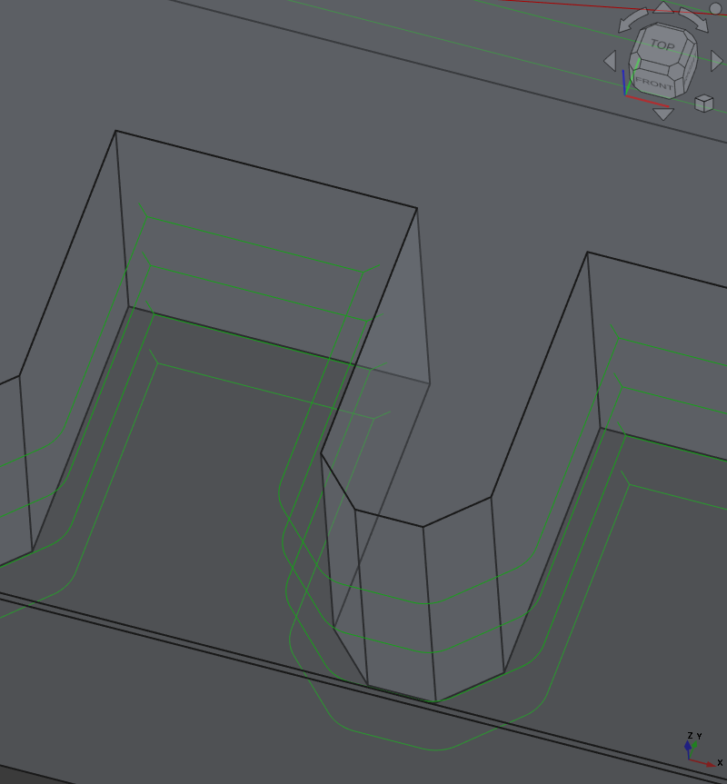
Next I started a ‘Profile’ tool-path and selected the shape I want to mill around.
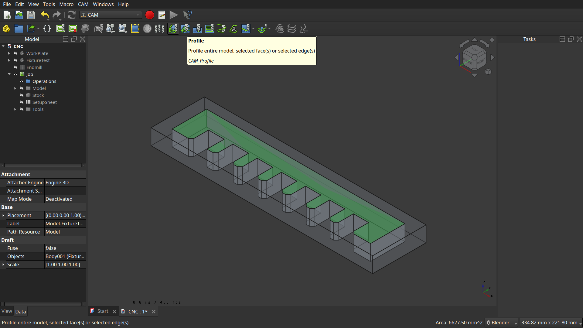
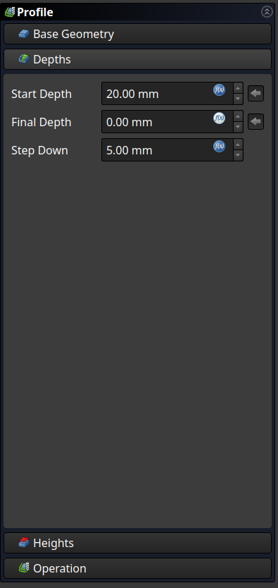
<- Important there is the start and final Depth (also step-down, which uses the tool diameter initially).
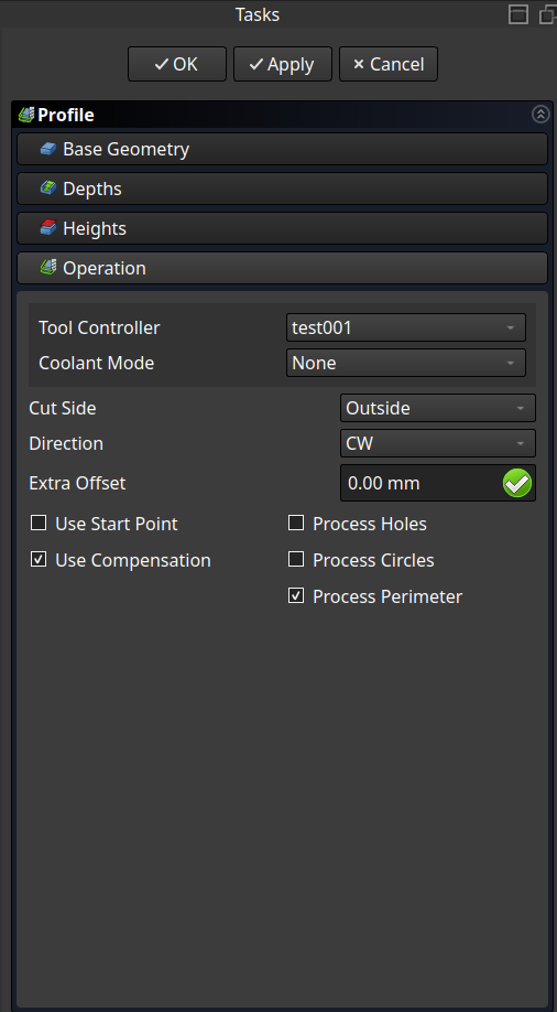
Important here is to choose the tool.
Note
Also important to note, we model, that Z==0 on the bottom of the workpiece, which inherently constrains the tool to move into to bet. Also in the ‘Heights’-Tab the Safe Height and Clearance Height (travel distance to bed of CNC) is configured.
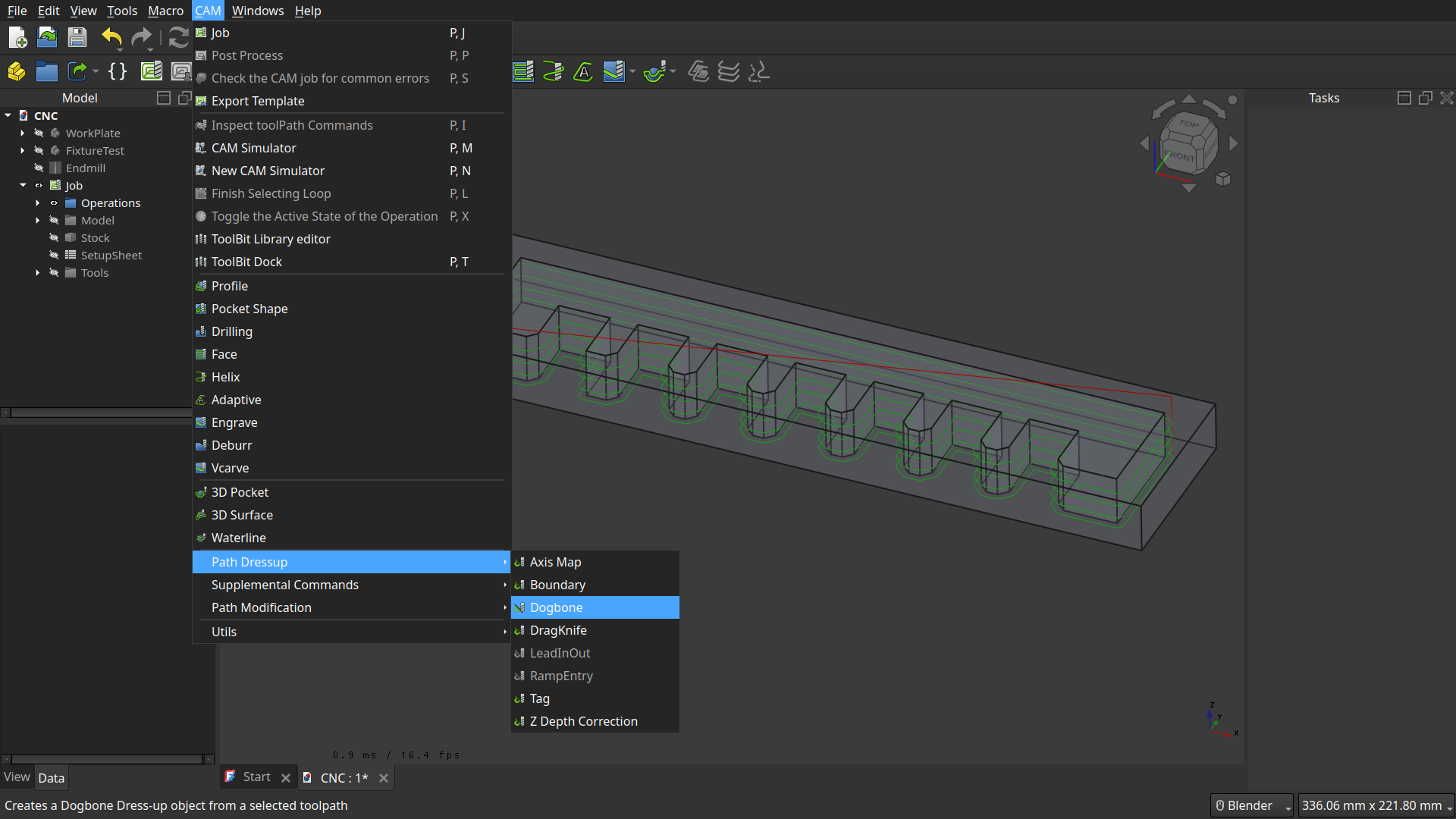
Dog-Bones and Bridges (in FreeCAD called ‘Tags’) are a dress-up and can be found in the CAM menu under ‘Path Dressup’.
Important
First select the path you want to apply the dress-up to!
Dog Bones
It just generated dog bones on inward corners.
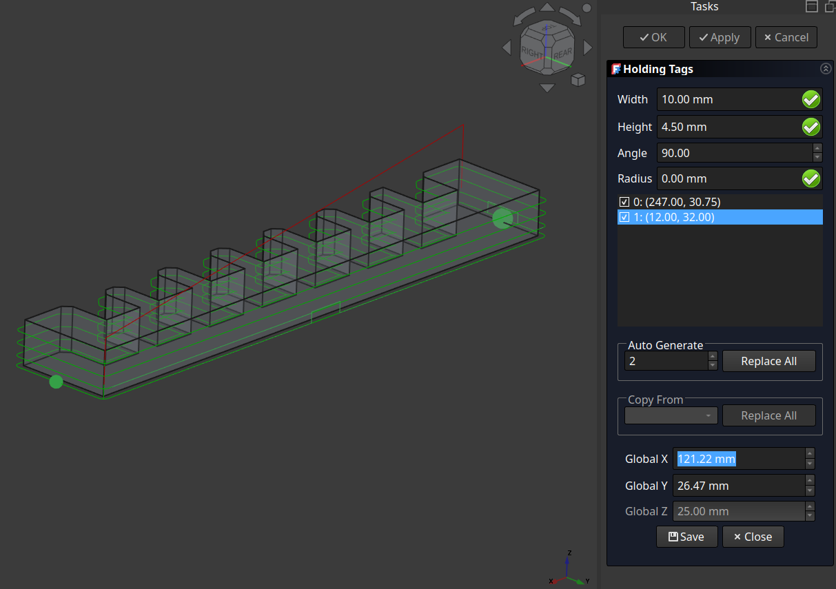
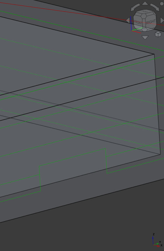
Bridges/Tags
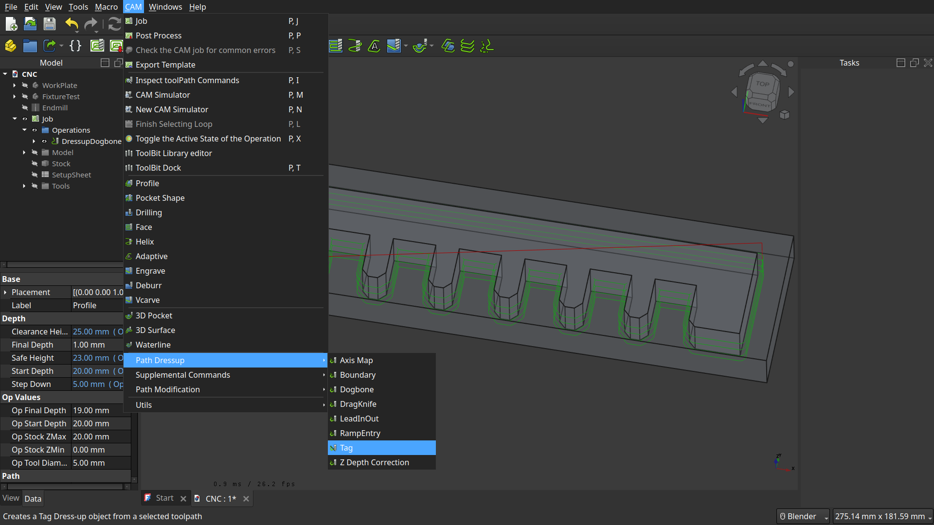
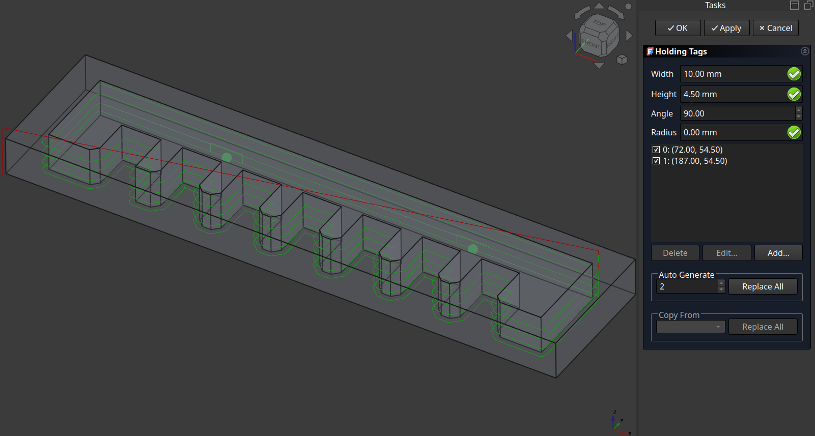
Here you can add more bridges and also move them around:
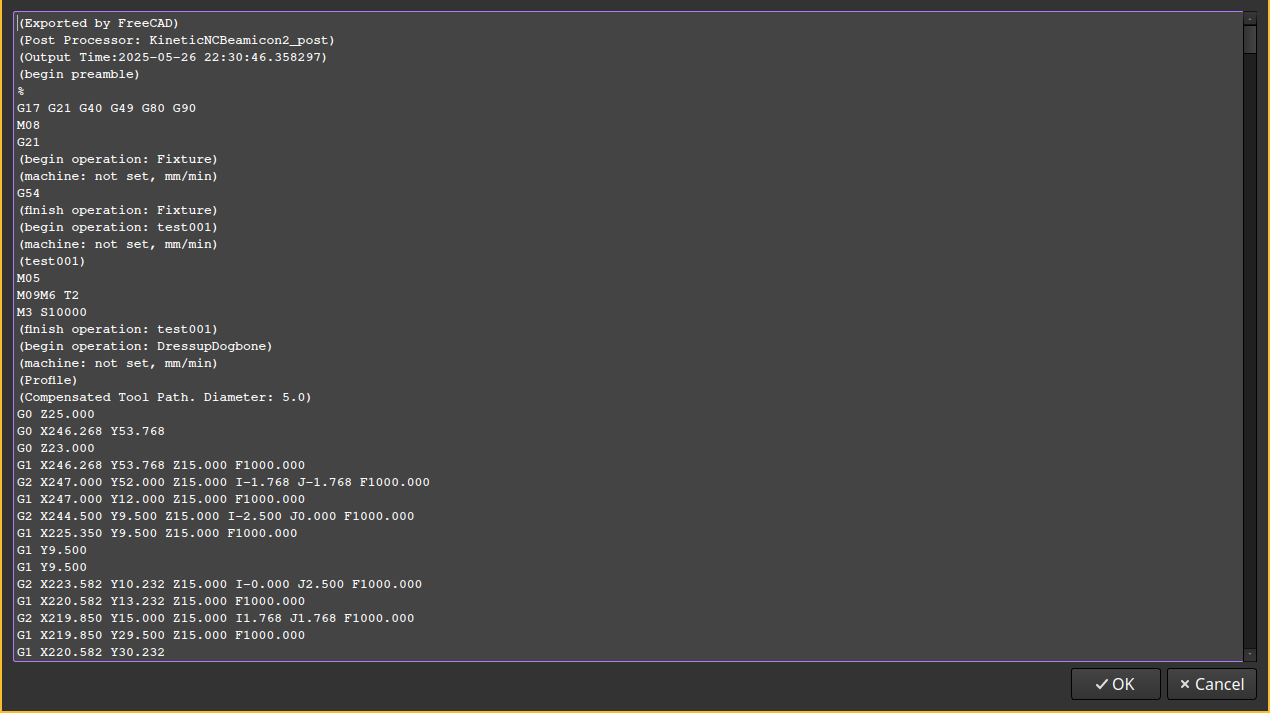
Then to Export, you choose Post Process:
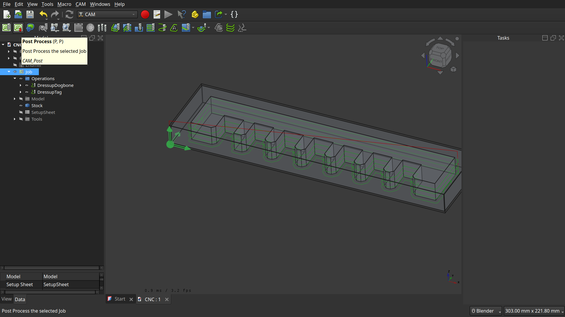
Look at the G-Code and save the file.
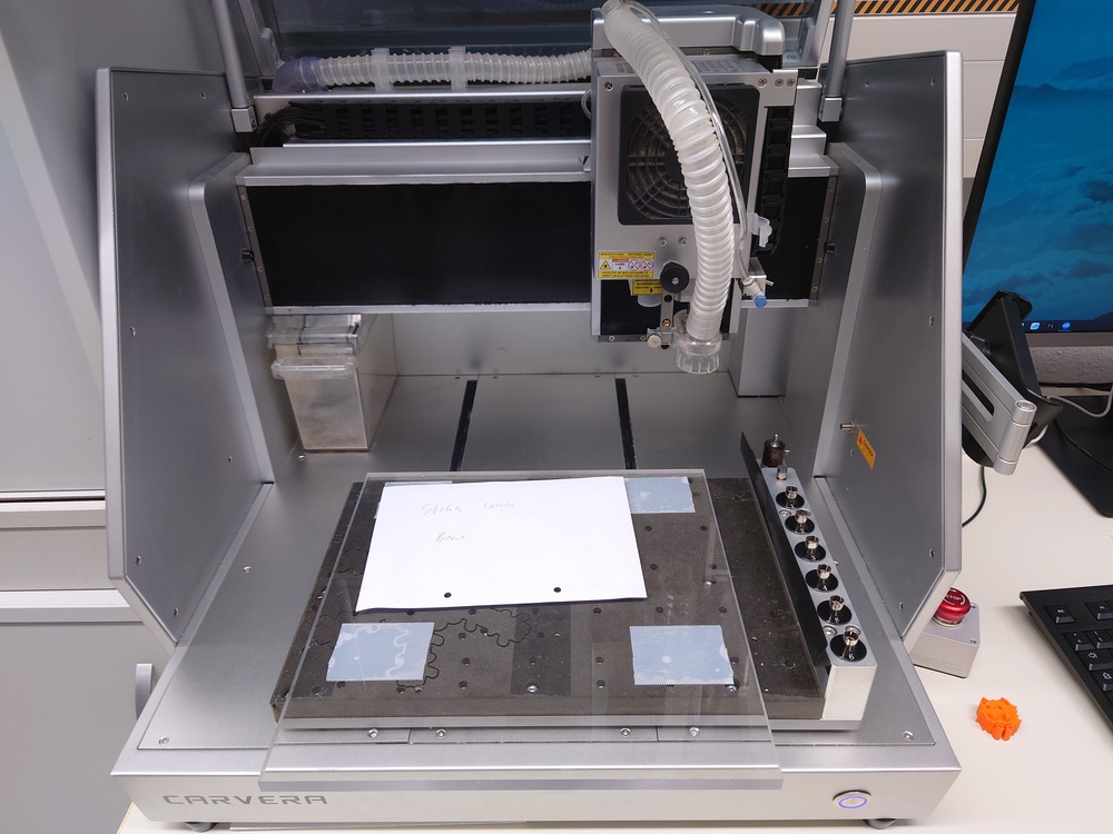
Milling
First we clamped the wood:
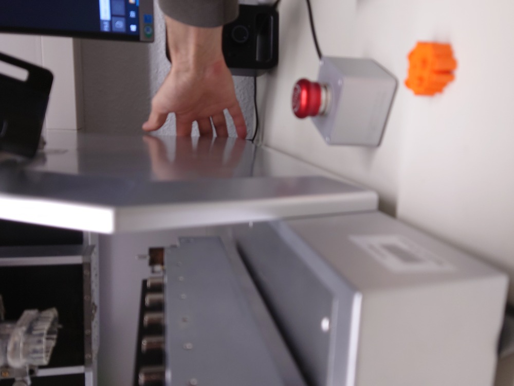
The Powerswitch of the Carvera is on the back side.
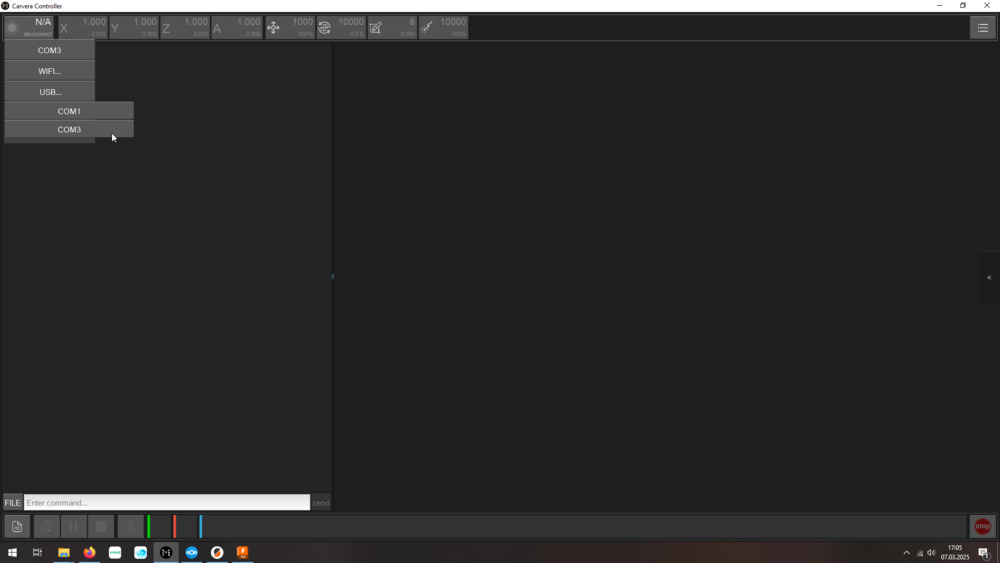
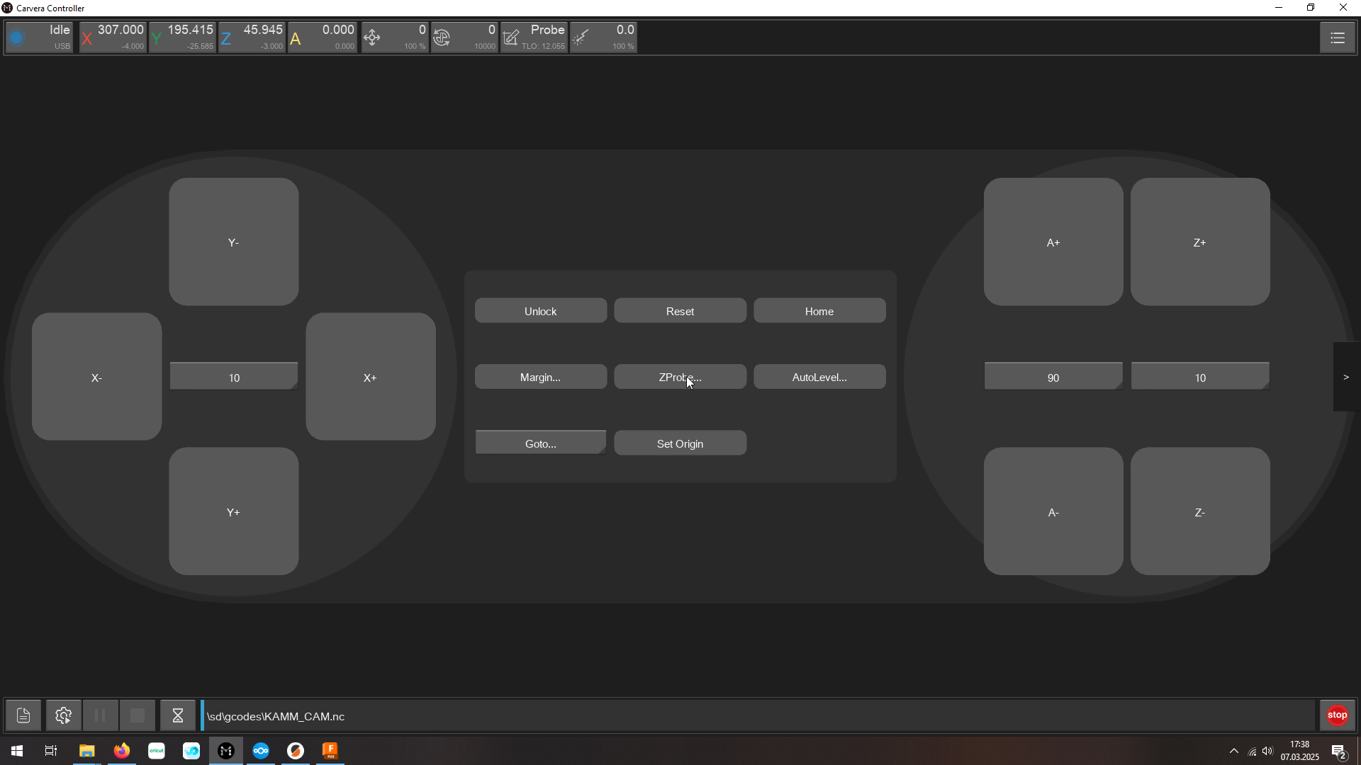
Then Start the Carvera Controller software and use the top left button to connect to the it (USB).
If the CNC was previously halted, you need to unlock the machine, so the motors can move again.
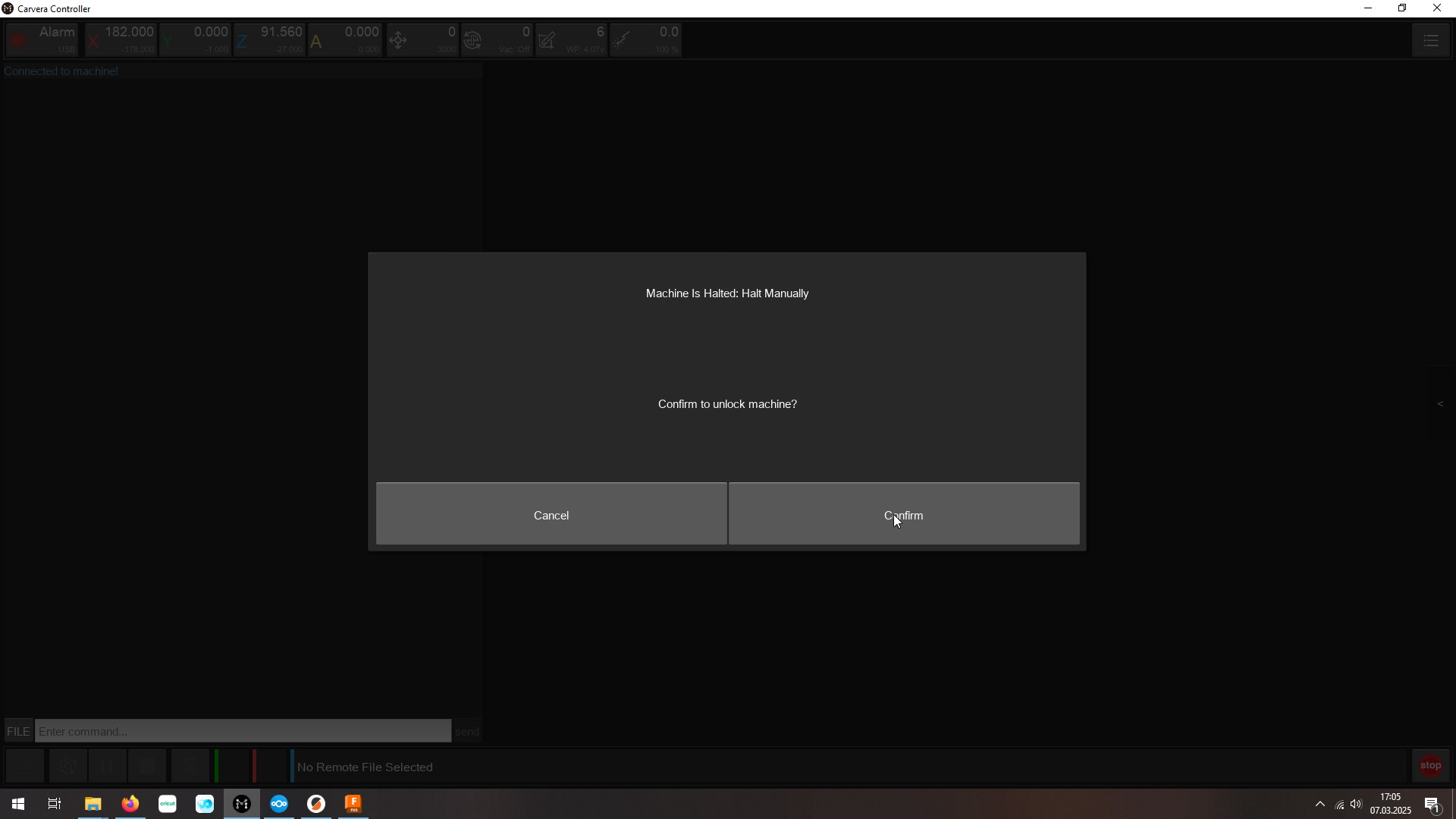
Tip
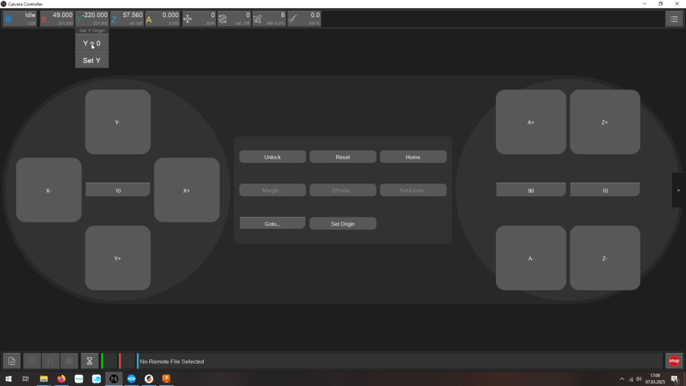
On the right side is the software-controller to drive the axis.
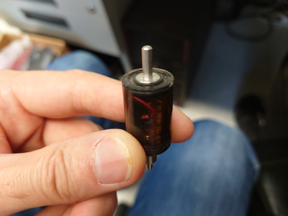
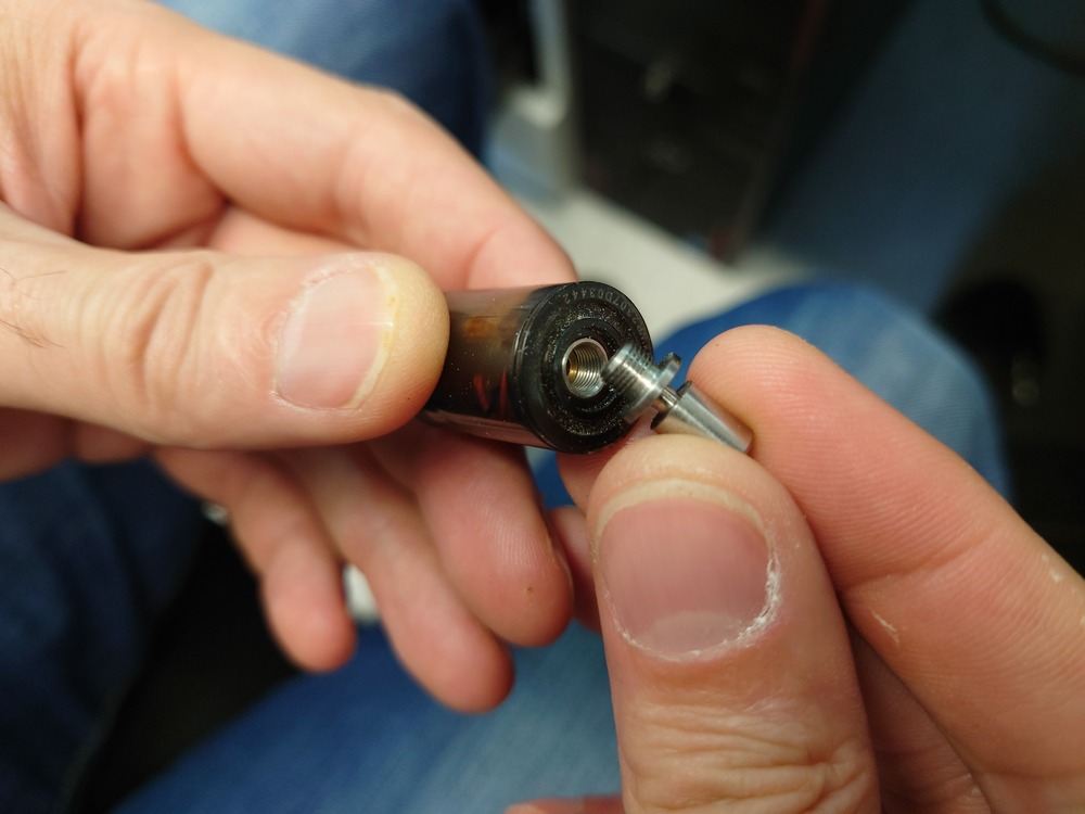
Then we used the probe end to find the bed zero. Therefor, because we used a different mill, we needed to change the end of the mill so it fits into the CNC Head.
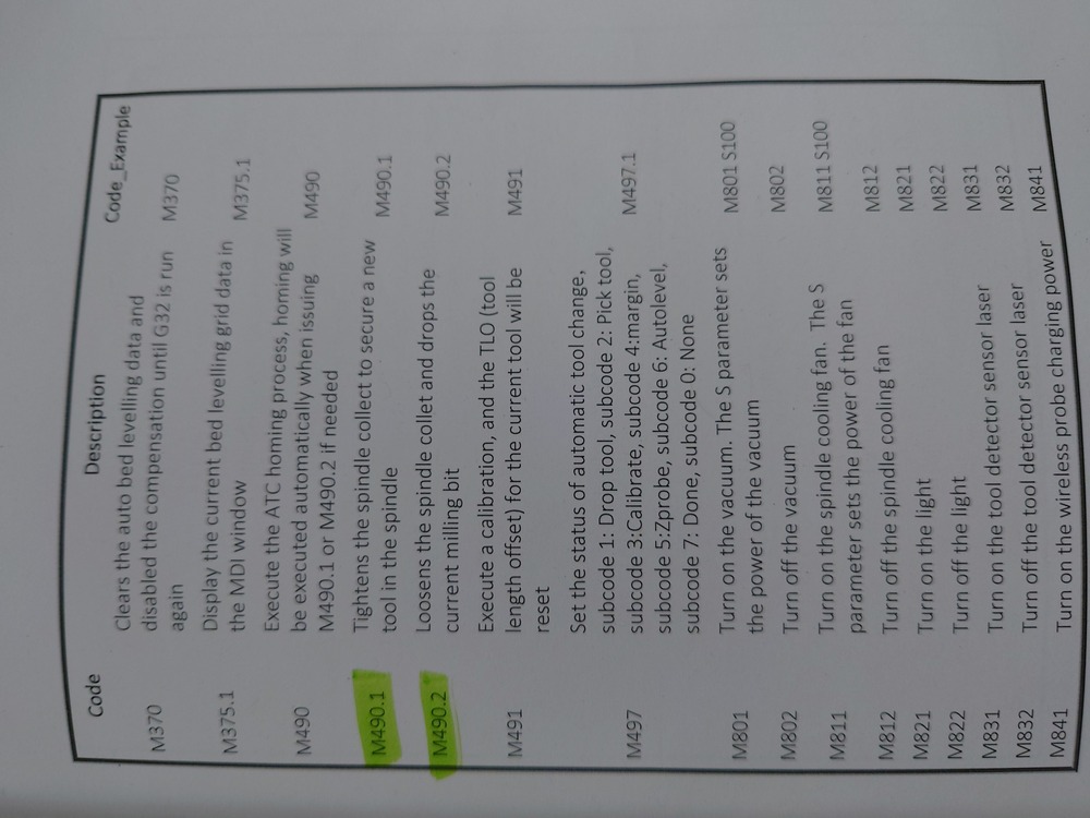
Gcode to tighten and lose the spindle shank.
And then use it to set the z zero.
Then we set x and y to zero on the workpiece (by driving to a suiting point) where we wanted to start the milling.
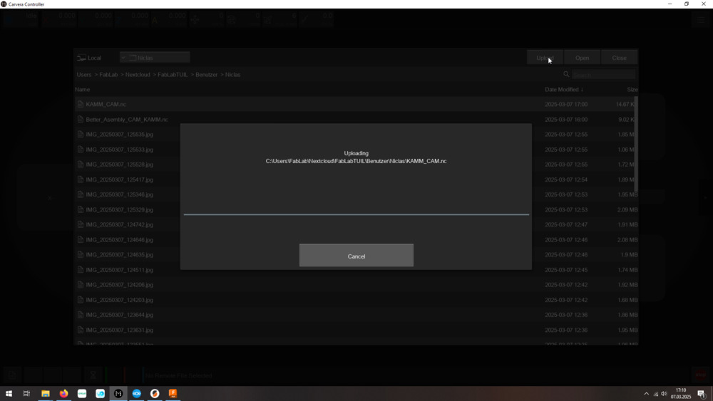
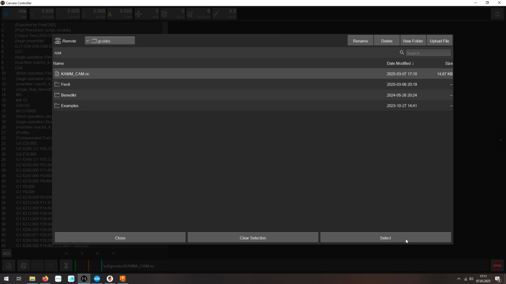
Then we need to upload the file to the machine and then select it again for milling.
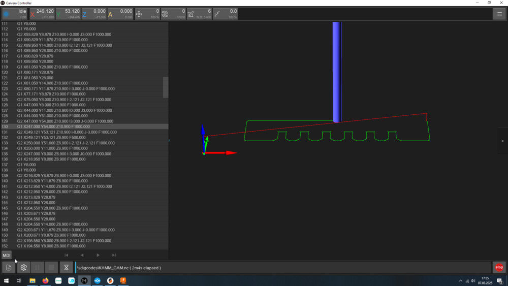
Loaded GCODE:
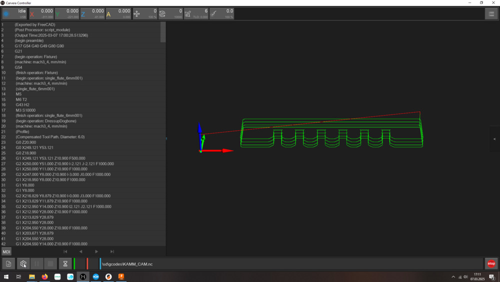
And then start milling, but deselect ‘Scan Margin’ and ‘Auto Z Probe’.
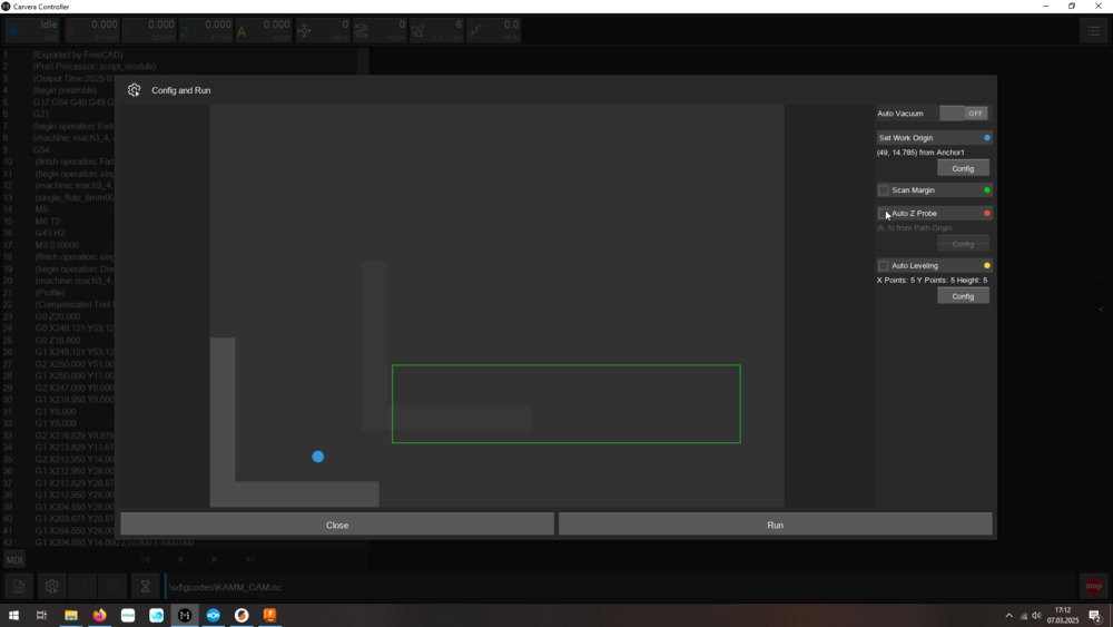
We just milled in the air to test out the G-Code (here I found out, that I forgot to set the RPM in FreeCAD).
I corrected my mistake, we reset the Z value to the measured one and started milling:
Tool change:
Milling:
Finished:
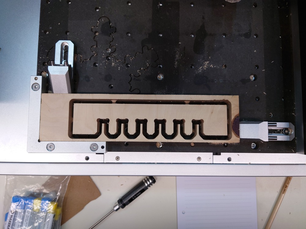
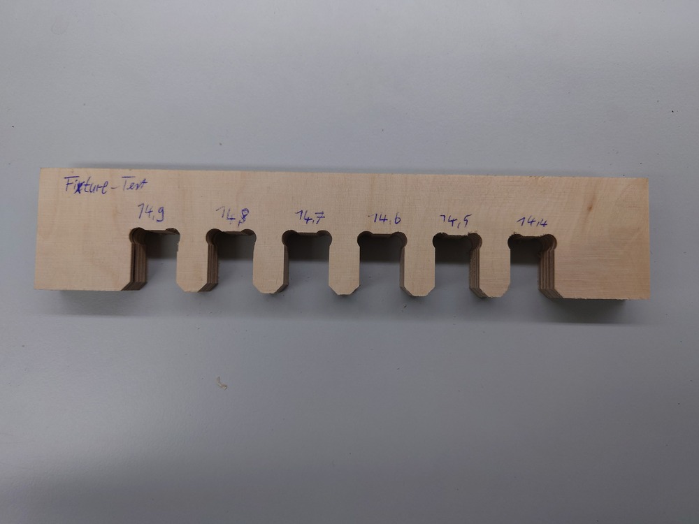
So for this wood, the good fit was at 14.7mm.
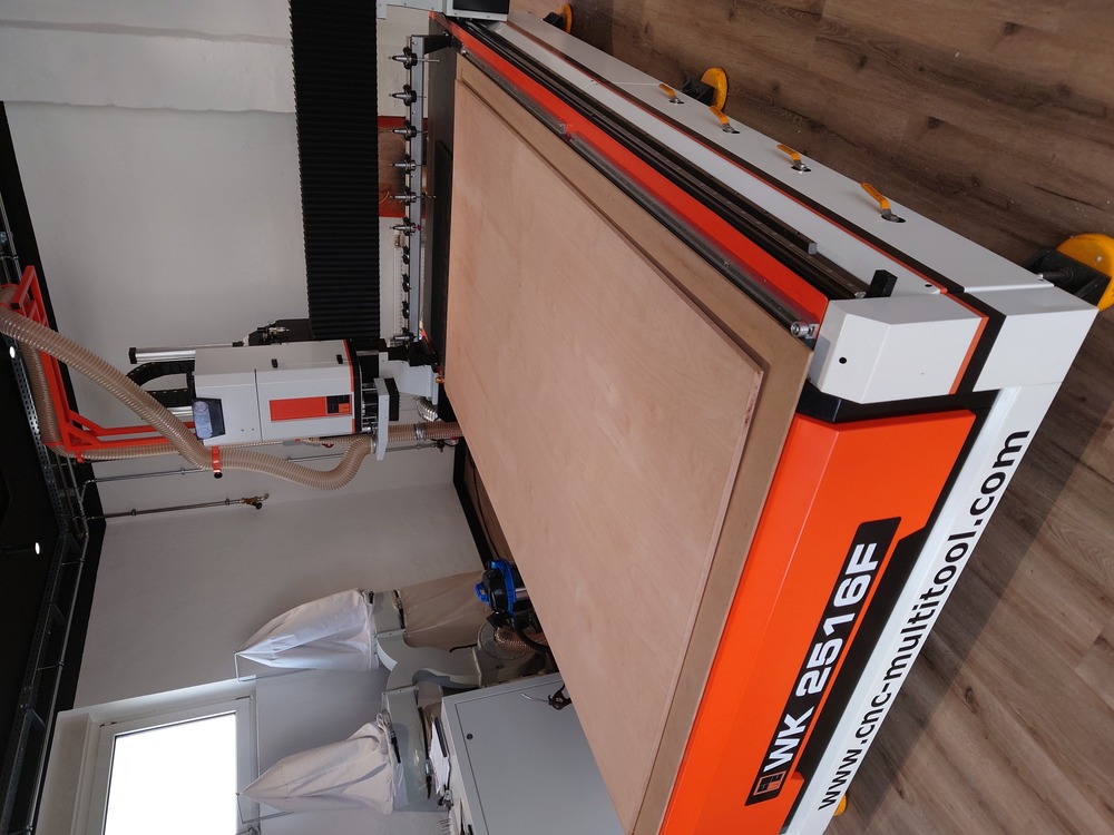
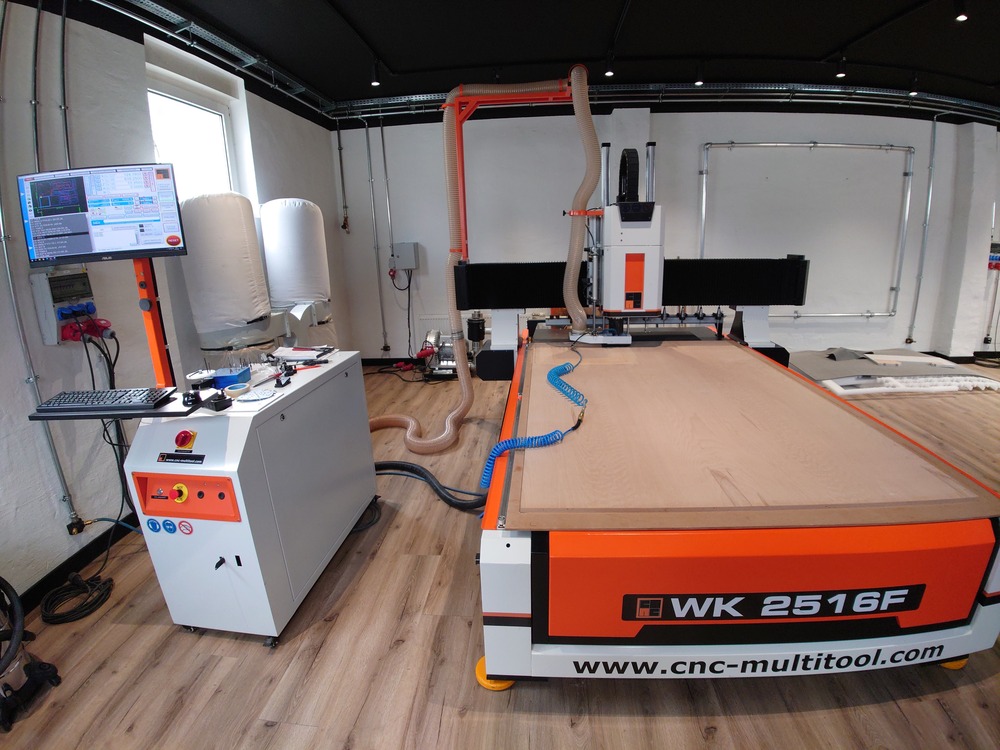
7.2.4.2. Custom CNC AC2513F from CNC-Multitool
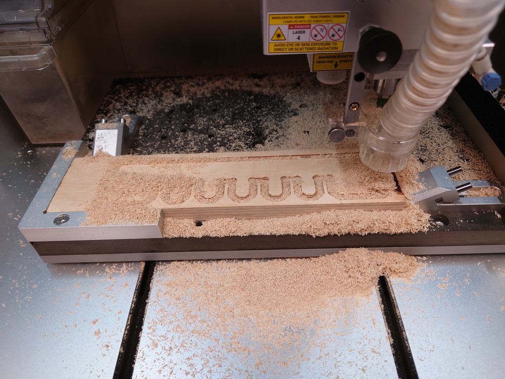
We also here milled the comb on the actual material to test the fixtures:
To see more from the process, look into the Group Page.
The CNC:
Milling:
The Comb:
Outcome
tabs where bigger then needed, 3mm sufficient
Fixtures where nice and tight at 17.8mm where the Material was somehow 17.6mm
-> 0.2mm more offset
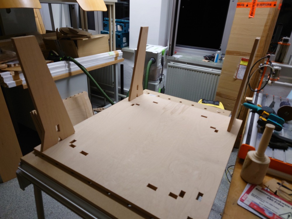
7.3. Individual Assignment - Make something BIG
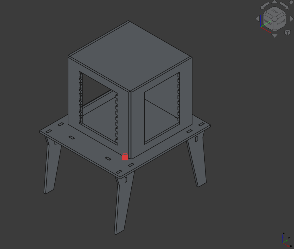
I’ve decided to build a Table with housing for my 3D-printer @home.
7.3.1. Design
It took me some time to get used to designing a parametric assembly (and also getting used to the CAD-style designing) and I had to restructure my files a few times. But now I think I’m more used to the workflow in FreeCAD now and I really like this kind of modelling.
I wanted to make an housing that is easily constructable (no fasteners) and don’t uses conventional doors and also want to have enough space to work on the 3D printer itself.
So the concept is to have a scaffolding, which is plugged into the table and the sealing window-sides are attached to the scaffolding via magnets, so I can remove the hole side.
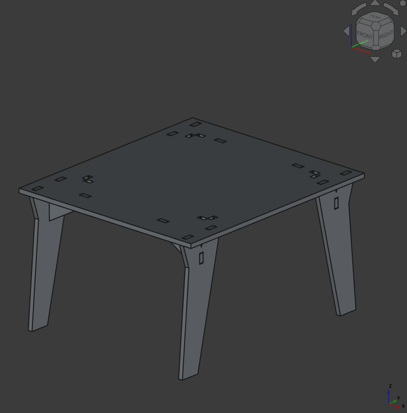
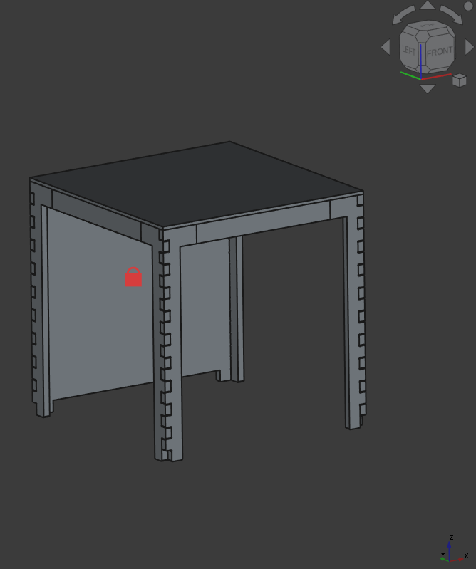
Table
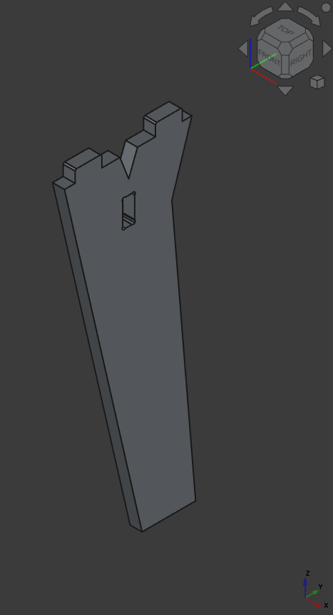 Leg
Leg
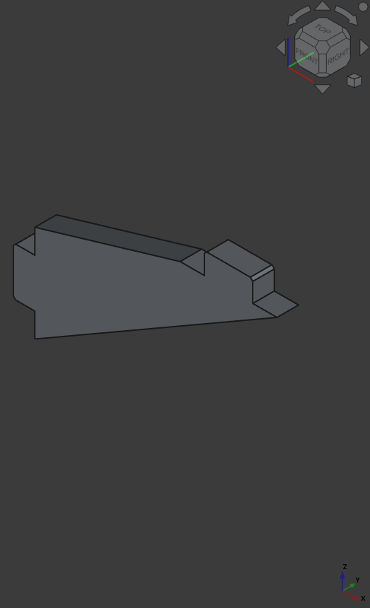 Support Angle
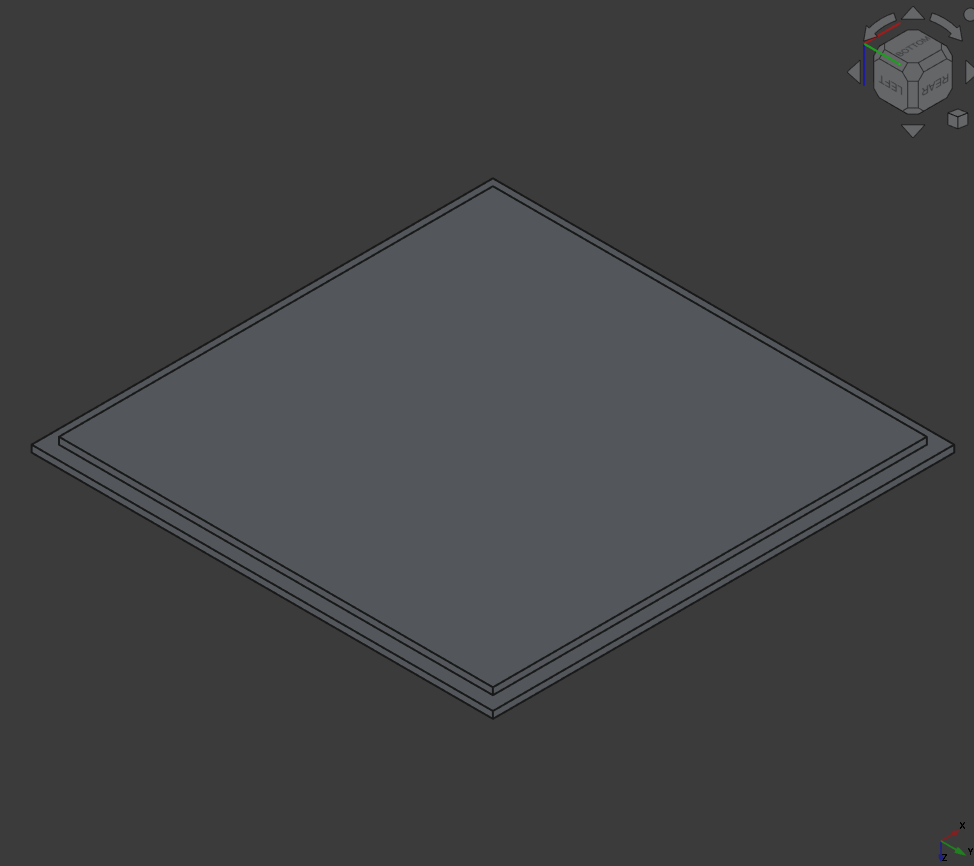
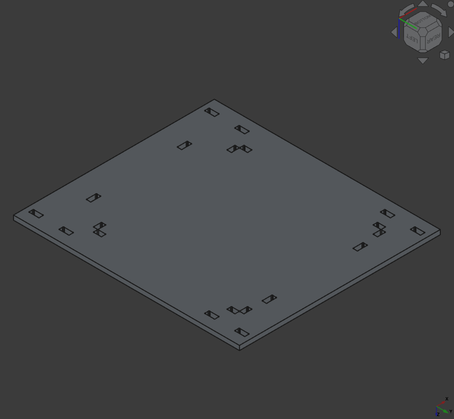 Table top with holes for the 3D housing
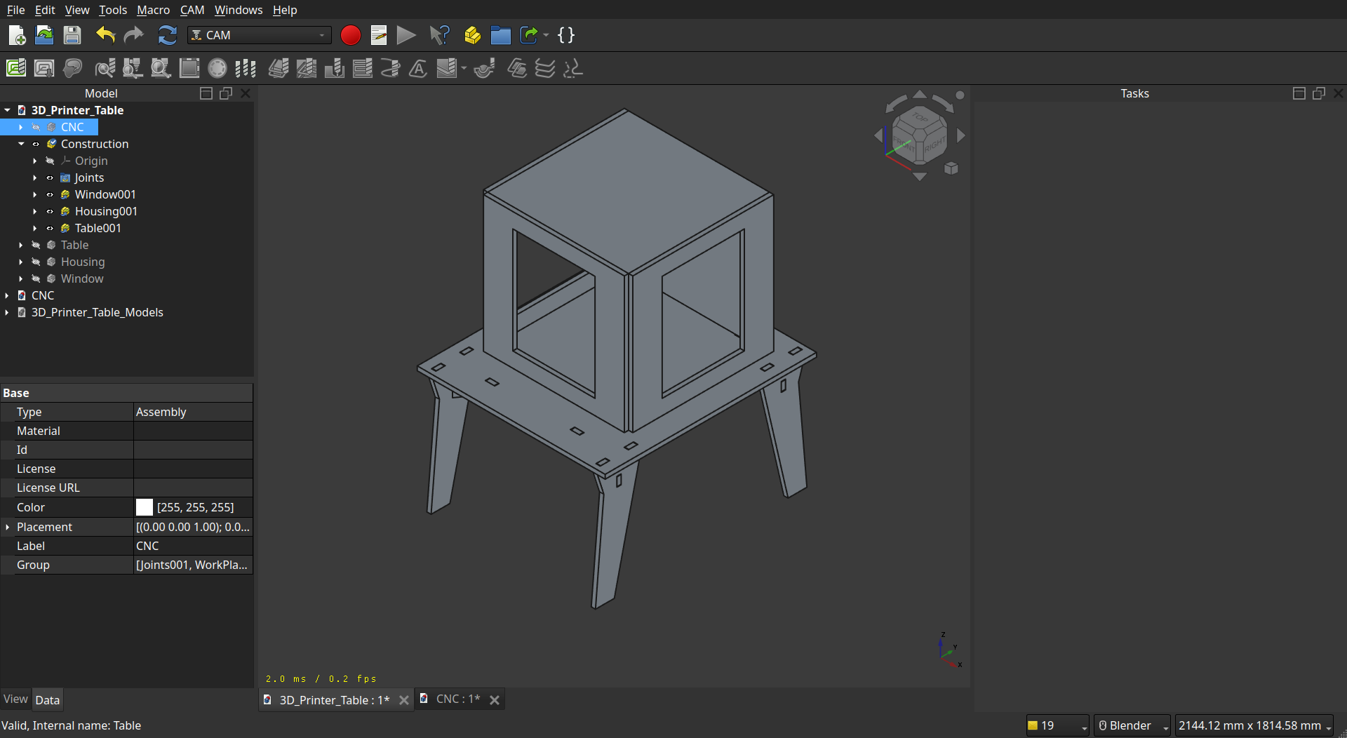
Assembled:
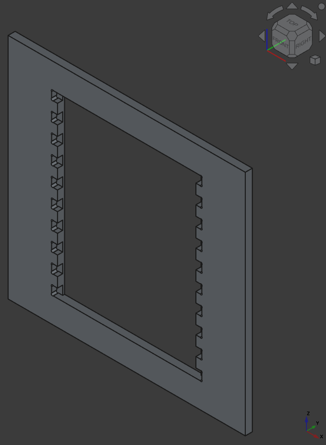
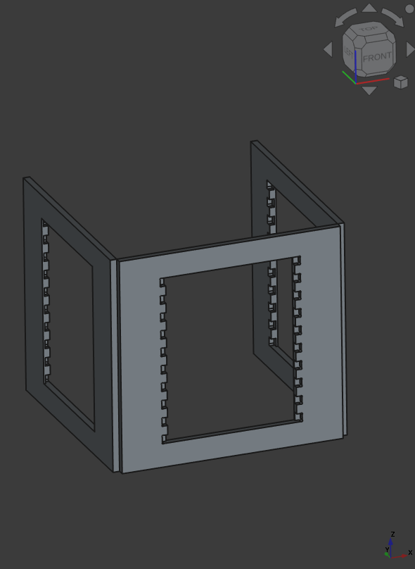
Frame
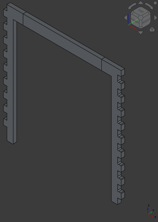 Side Frames
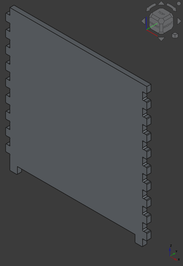 Back Side
Assembled:
Windows
Assembled:
3D Print Table Assembly
7.3.1.1. Learnings
use ‘inheritance’ for better parameter handling (in this Case I used the baseplate for the backplate and the frames just with little adjustments) so when I can easily create a base object and just create a reference to it to make adjustments
use linear patterns for repetitive actions to not make your sketch to big
creating a good parametric design is hard -.-
7.3.2. GCODE-Generation
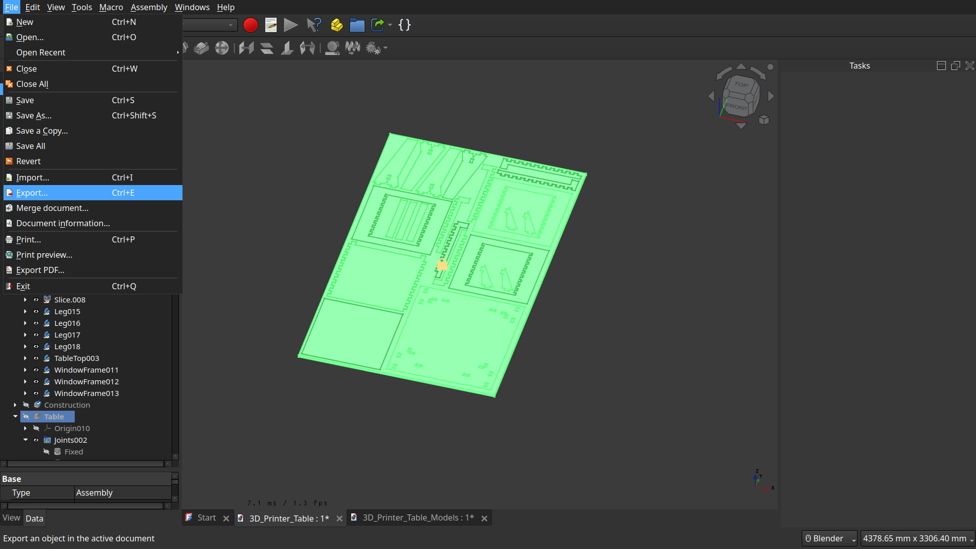
For generating the GCODE we used Solidworks Fusion360 because we milled at an external milling manufacturer and only got the generated code from fusion working properly.
So in my case to get the model of the CNC-assembled table I exported the model as STEP and imported it in Fusion, which worked perfectly.
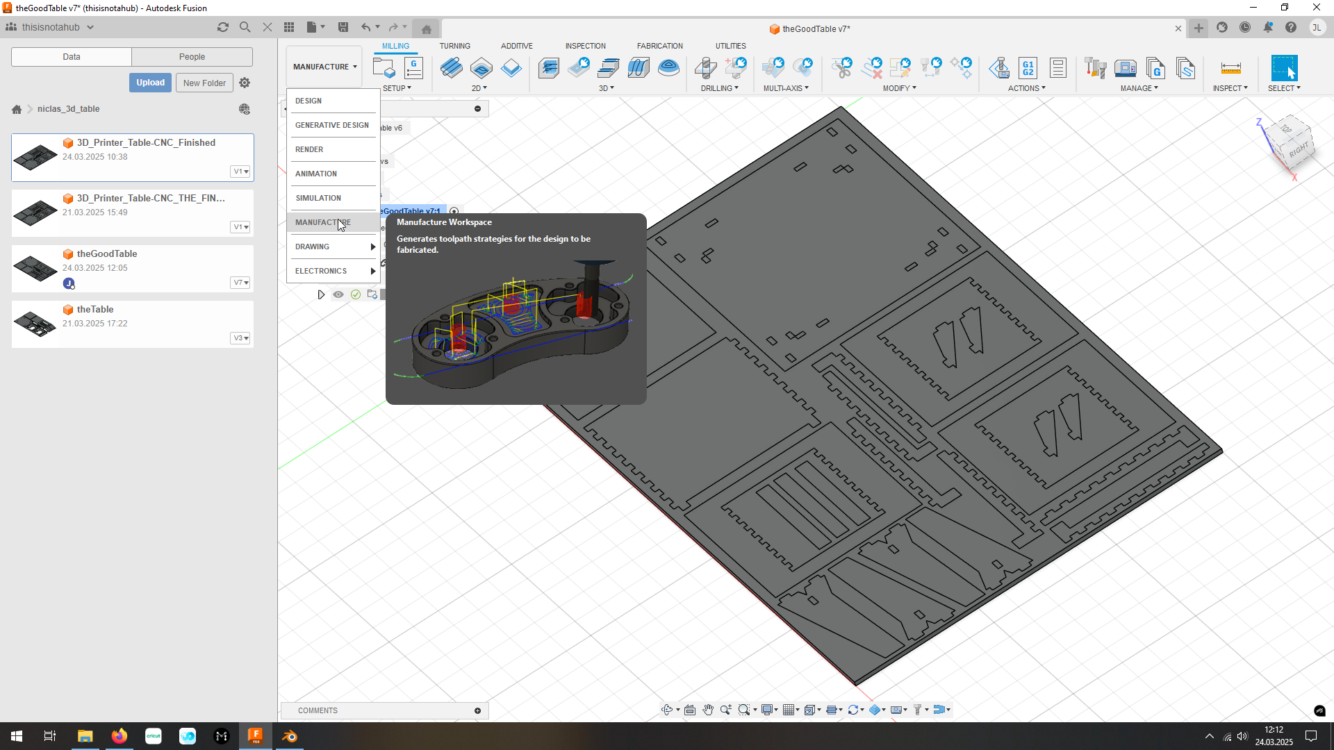
Next I adjusted the Origin and had to align some parts to z==0 (because I messed that up in FreeCAD ._.).
Then I changed to the ‘Manufacturing’-Workspace and created a new setup:
set the stock to the modeled workpiece
select all solids you want to mill
Important
Check the dimensions of the workpiece to match to the CNC (in our case 2400mmx1500mm) @CNC-Multitool the longer side of the workpiece should be on the x-axis!!
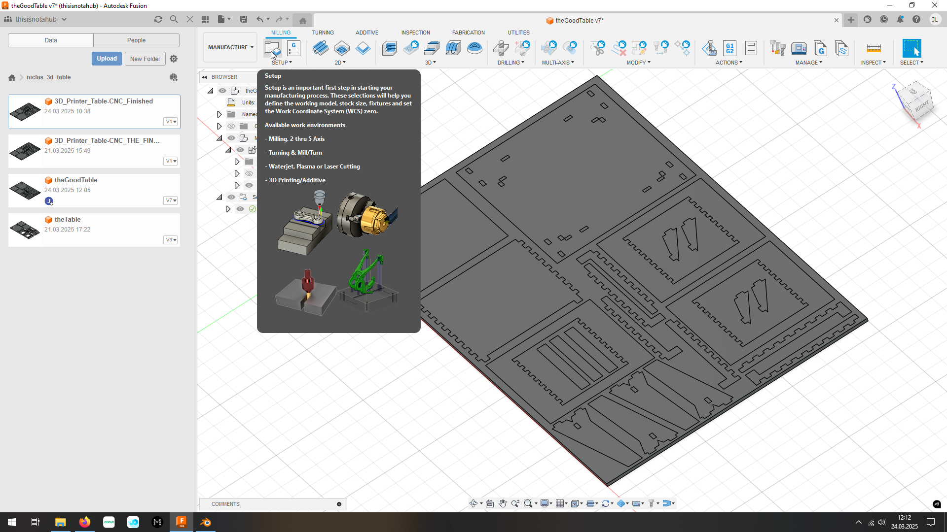 Setup a Manufacturing Process
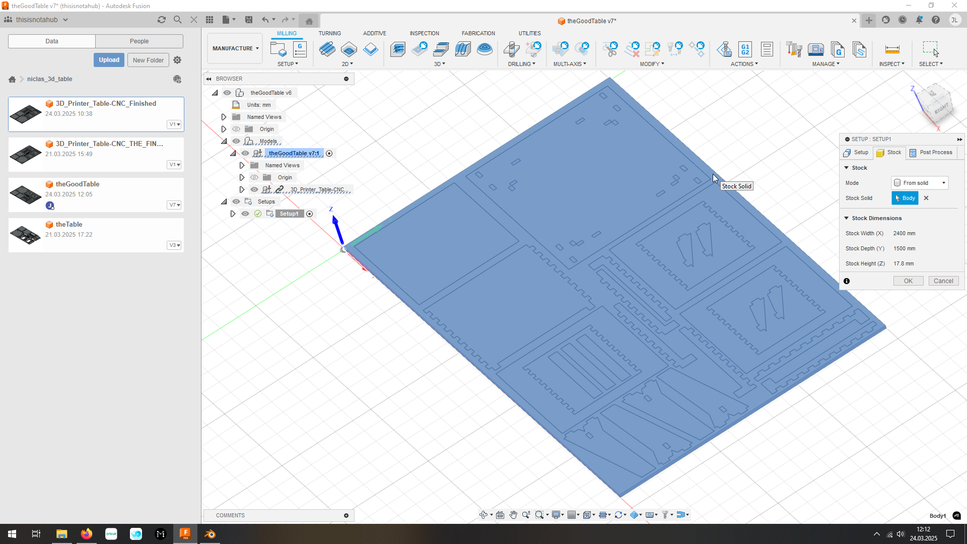 Choose the Stock
 Initial Settings (like tool and Speeds/Feeds)
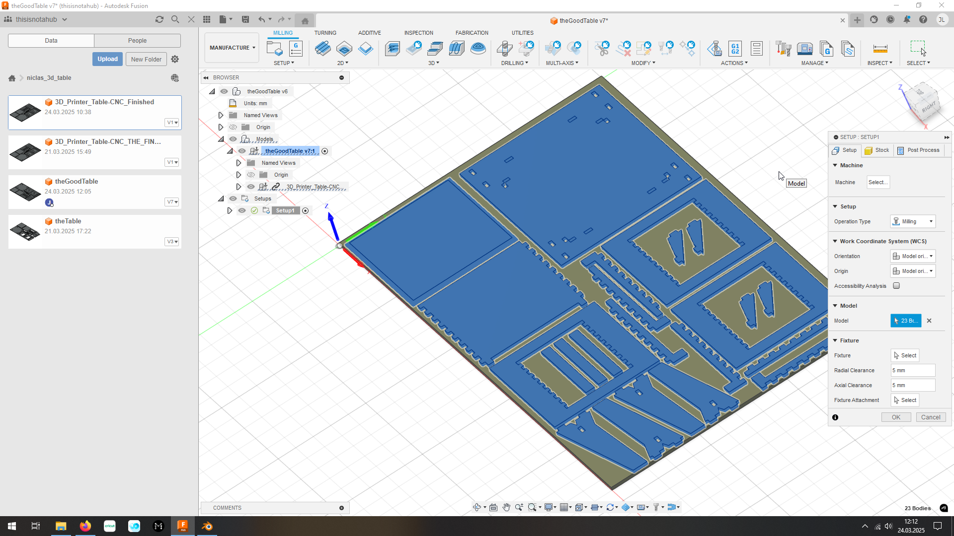 Choose the models to work on
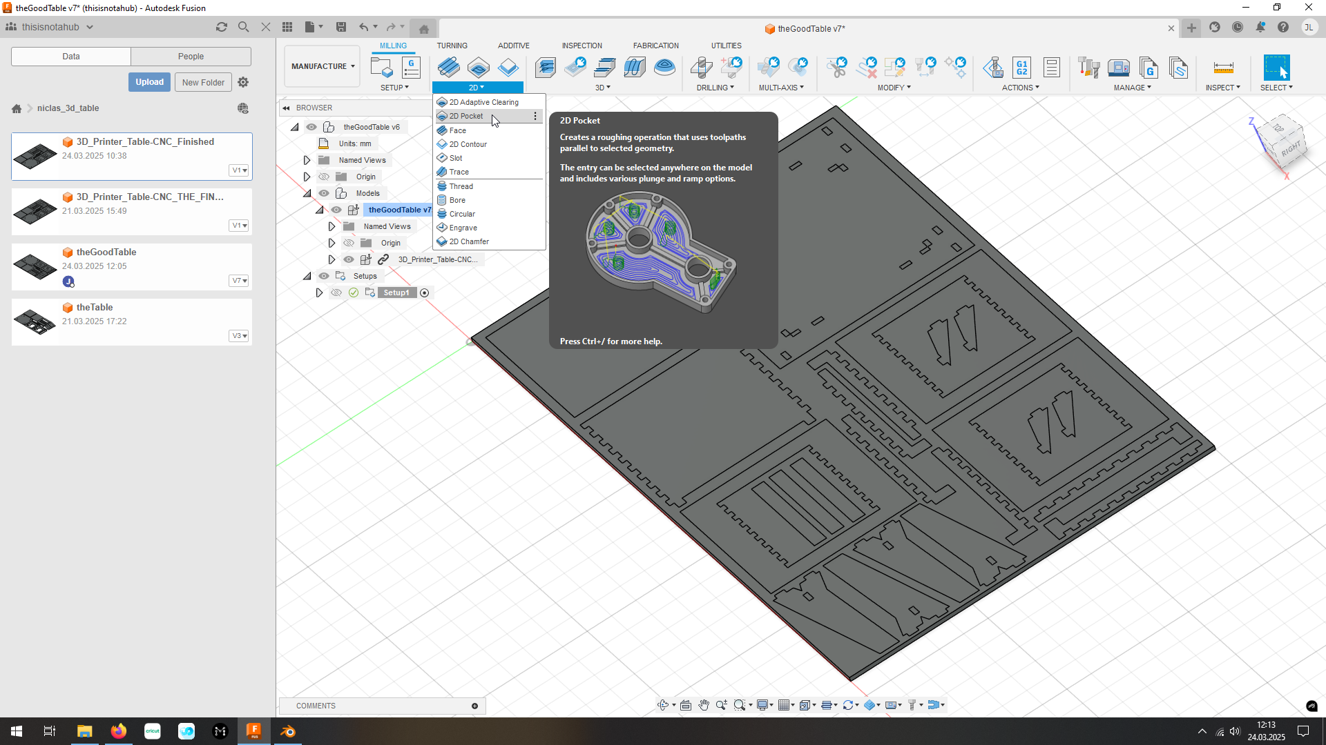
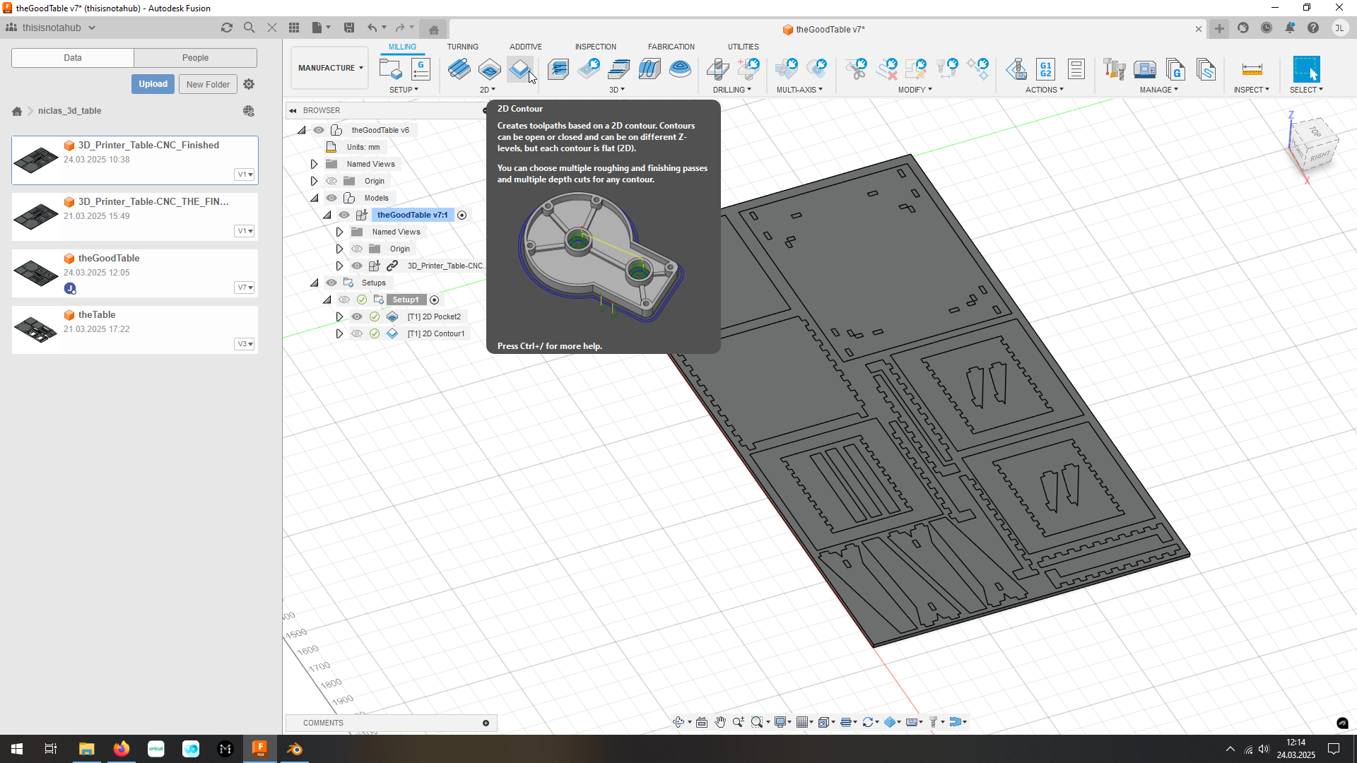
Now I can add ‘Jobs’ for different purposes, in my case I want to:
‘Pocket’ the holes for the scaffolding and angle, the fixtures for the windows and the outer part of the roof.
-> because a pocket-operation mills away everything of/to the selected part
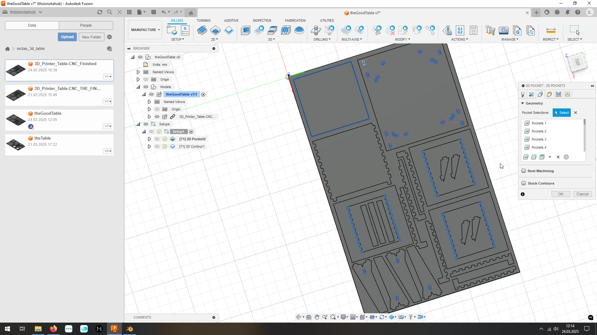 Choose the geometry you want to mill away
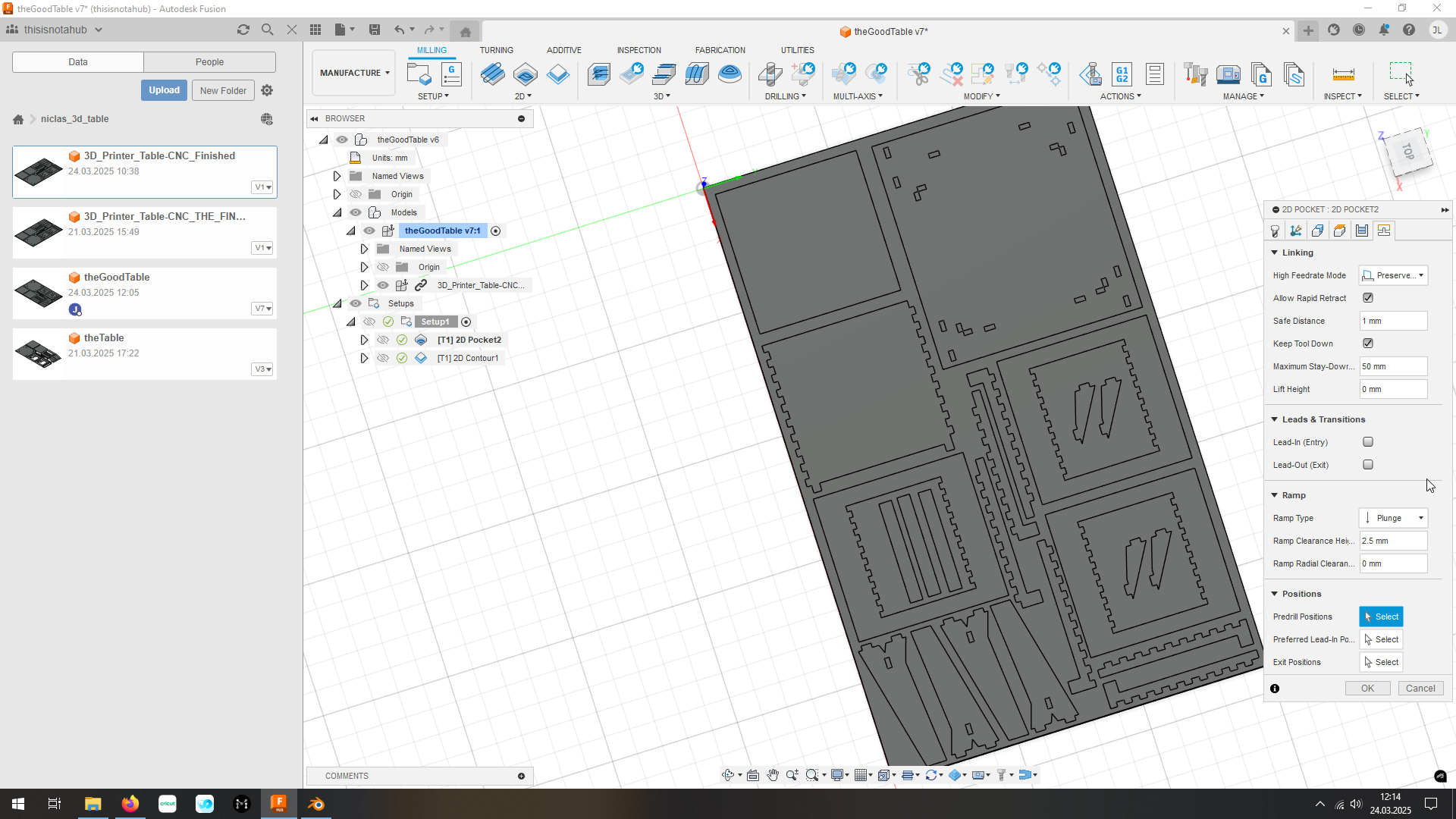 Disable lead in/out
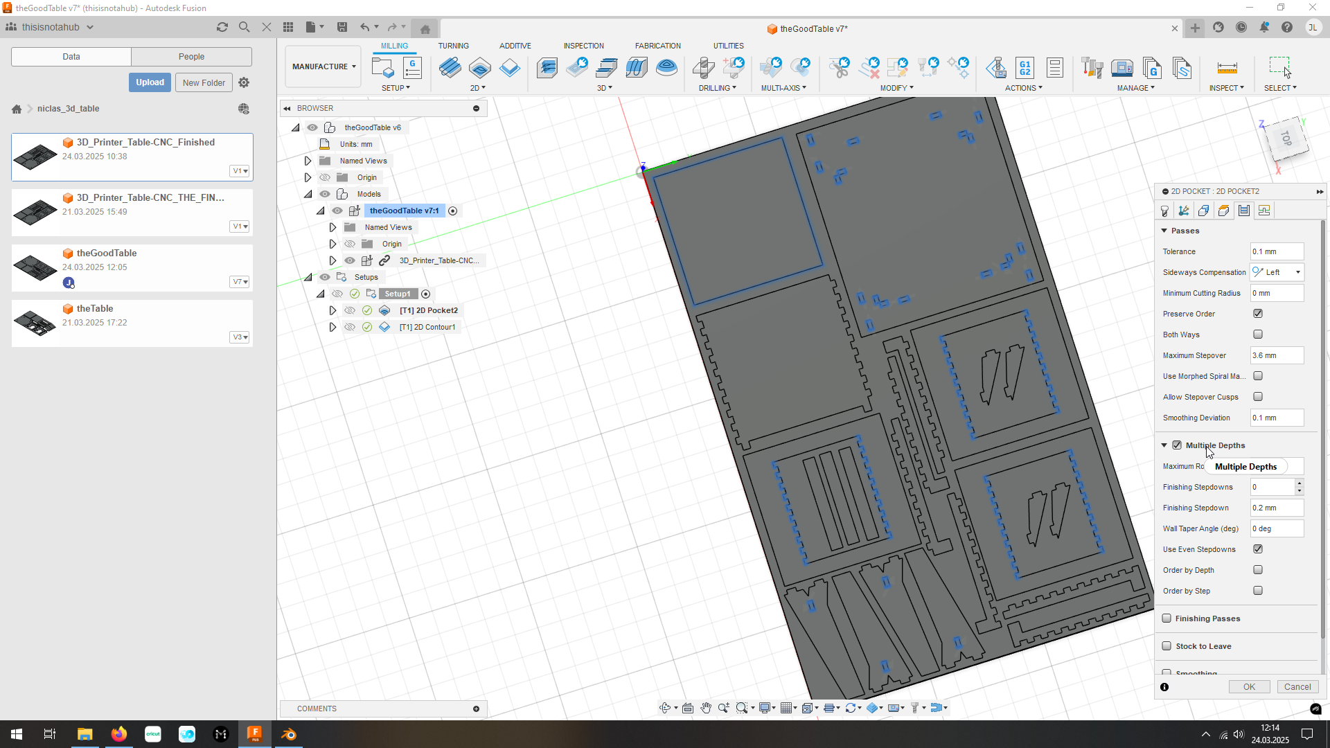 Enable multiple depths
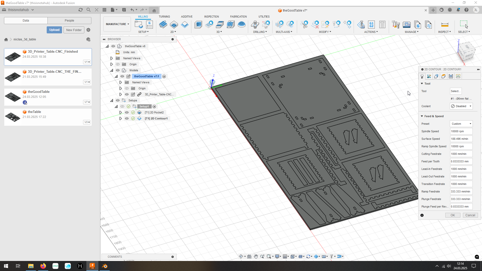
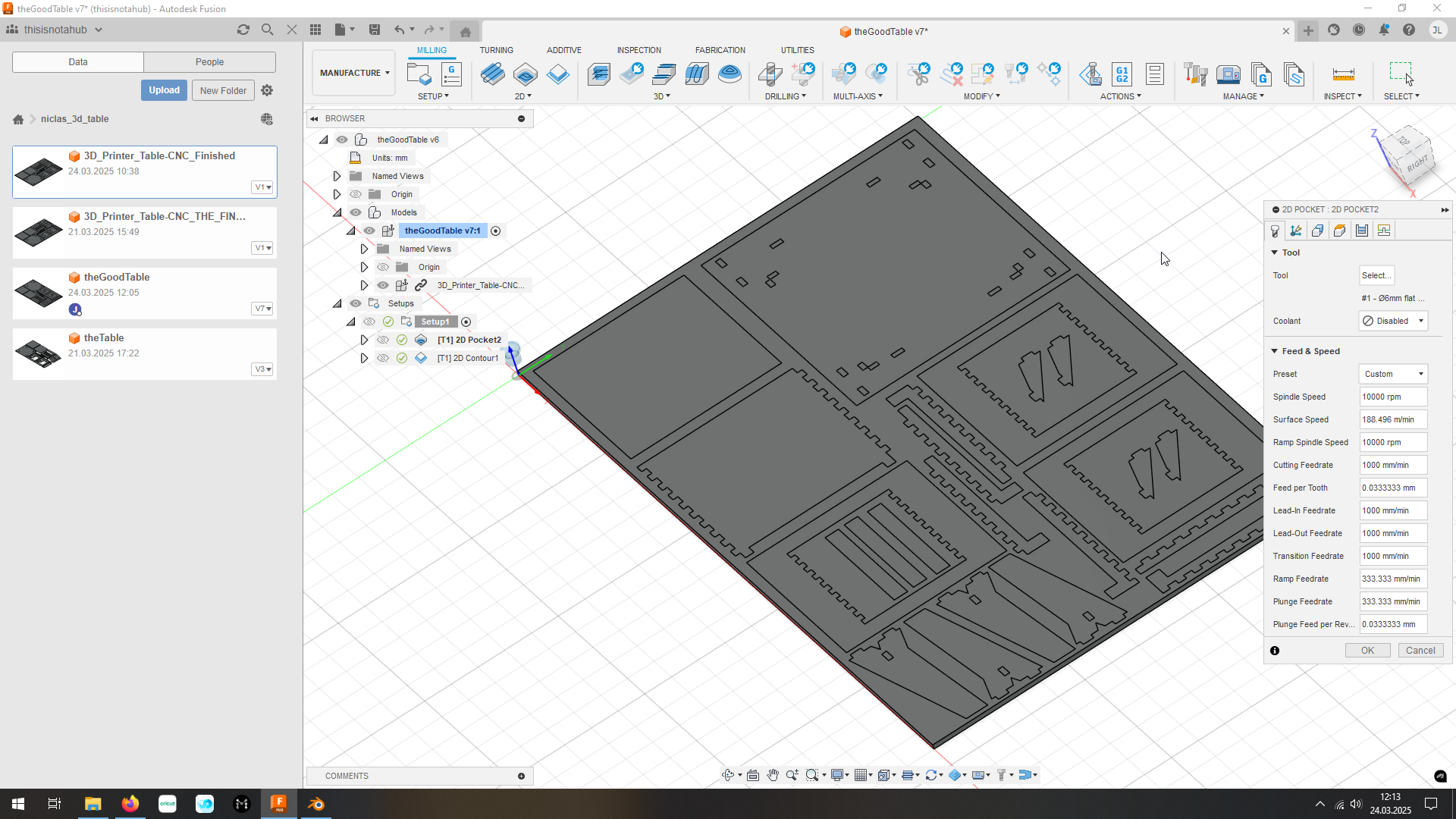 Configure Speeds and Feeds and tool
in geometry select the edges or faces to which everything should be milled away
in the last tab, set ‘Multiple heights’ on and sett it to 6mm to ensure that the mill is not milling away to much at once
also in the first tab set the tool (in our case a 6mm flat endmill) and I set the RPM to 10000, which we tested our CNC with
Path:
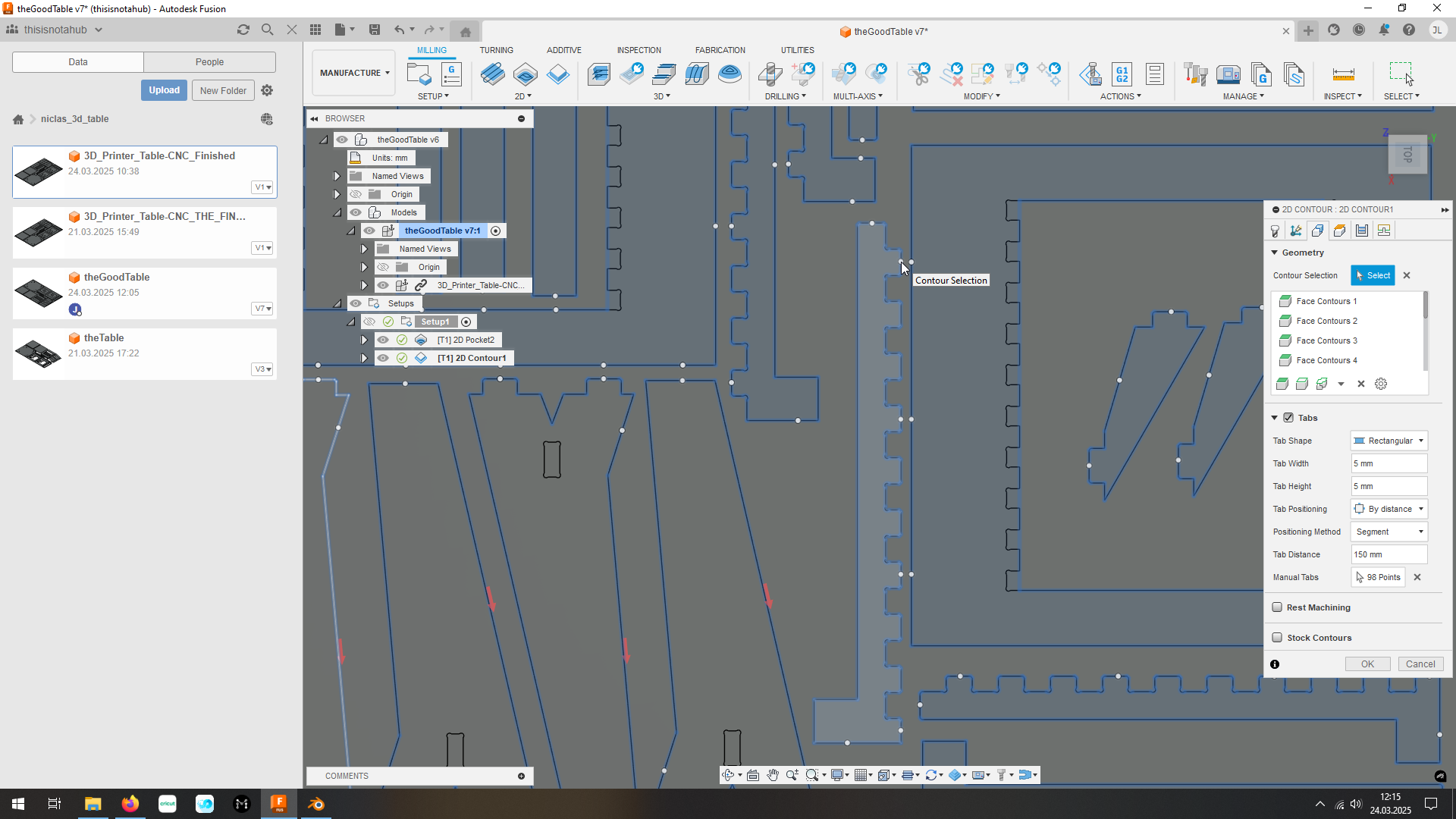
‘Profile’ the rest of the solids
-> because a profile-operation mills around the outline of the selected solid/face
 Choose the geometry
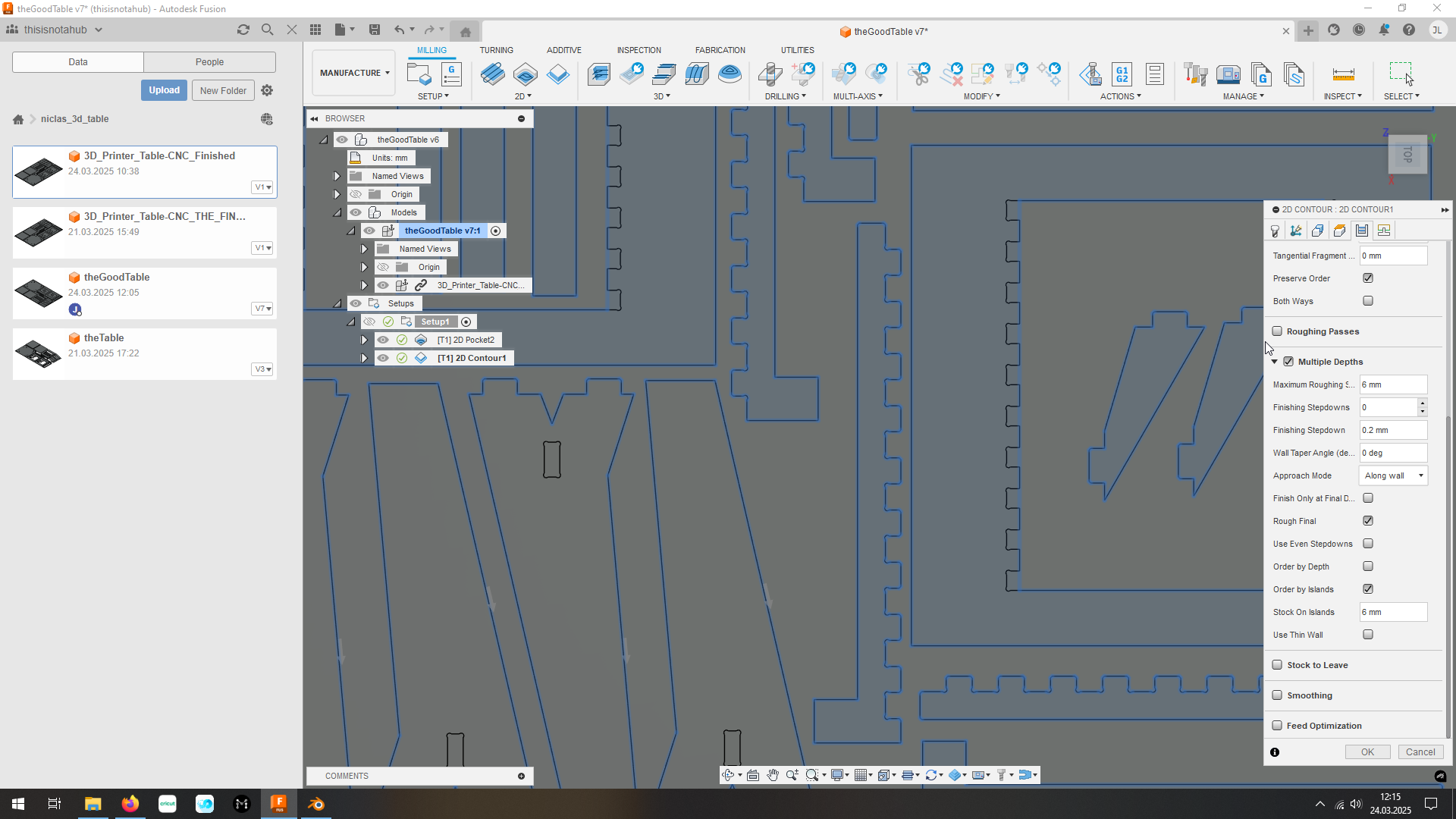 Add multiple depth again
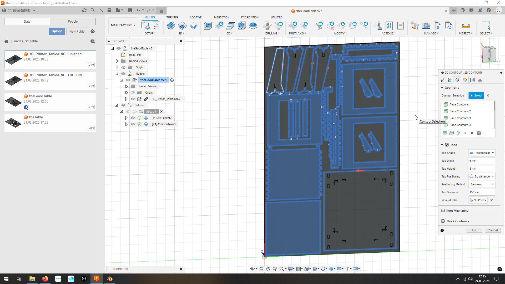
again on the geometry tab select every face/solid you want to mill out (recommendation, select from the bottom view)
select tabs and this will auto-generate bridges so that the parts are fixed and cant fly away when milling the last pieces out
I don’t want tabs in my fixtures so I used following settings to only auto-generate at every straight line longer then 150mm
Path:
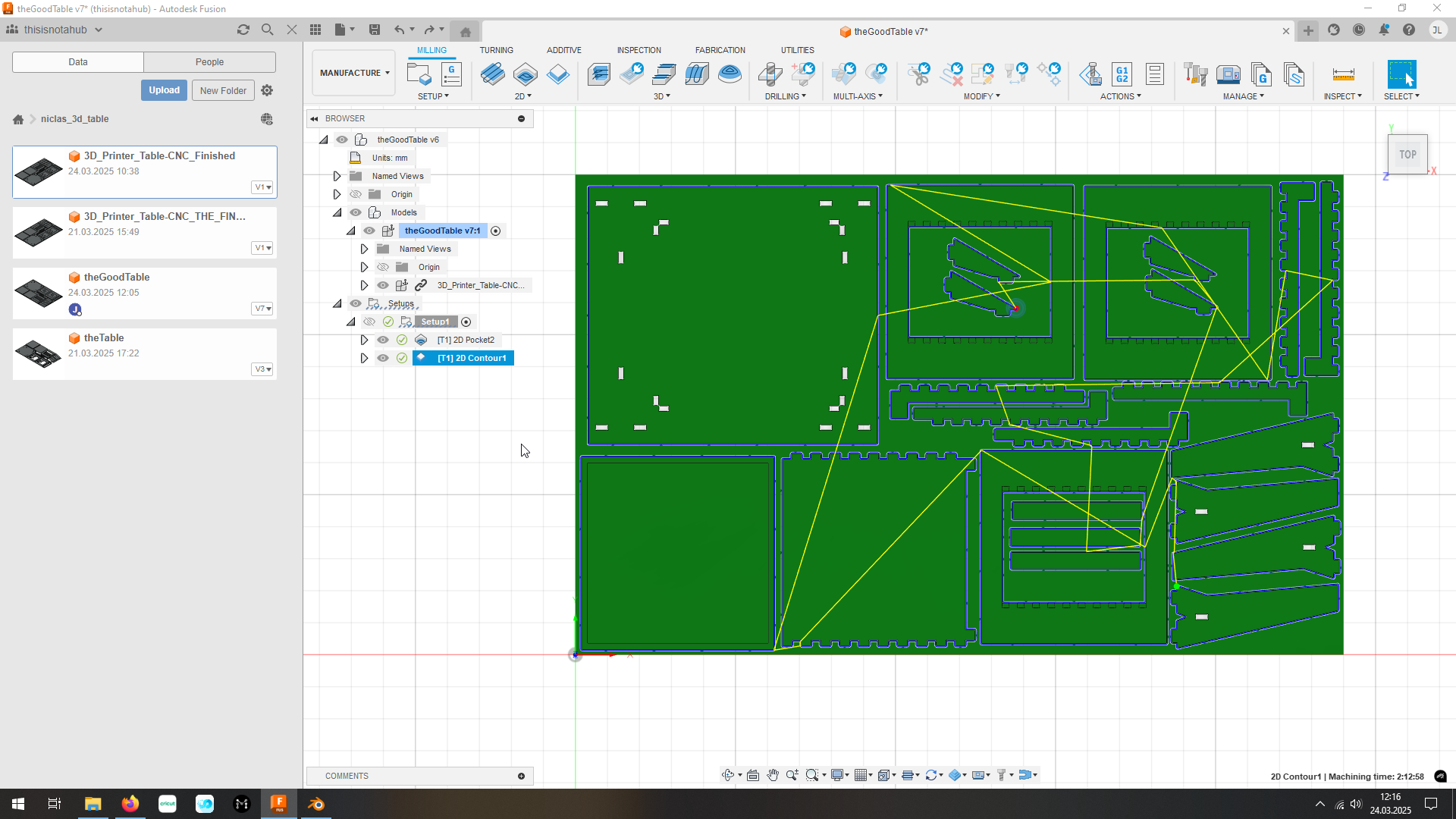
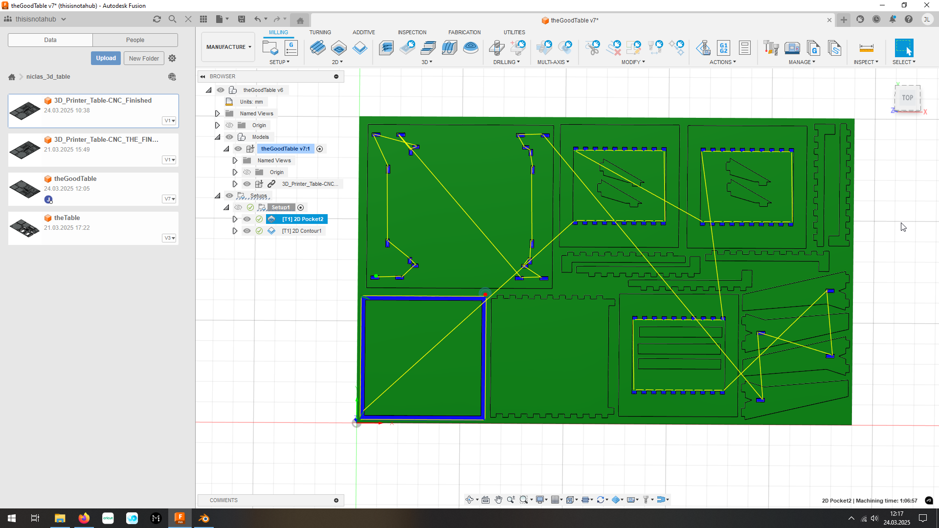
After looking over the generated path it’s also recommended to simulate (top right button ‘Simulate’) it to see, if the path is not strange in any way In the simulation I found out, that the CNC would drive unnecessary ways because of Fusion automatic-order of path I clicked
in the last tab of the operation I selected ‘manual order’ to change the order of generation to the order I selected the geometry
And if everything looks all right (also in the simulation), generate and export the GCODE (top right in ‘Actions’).
7.3.3. Manufacturing
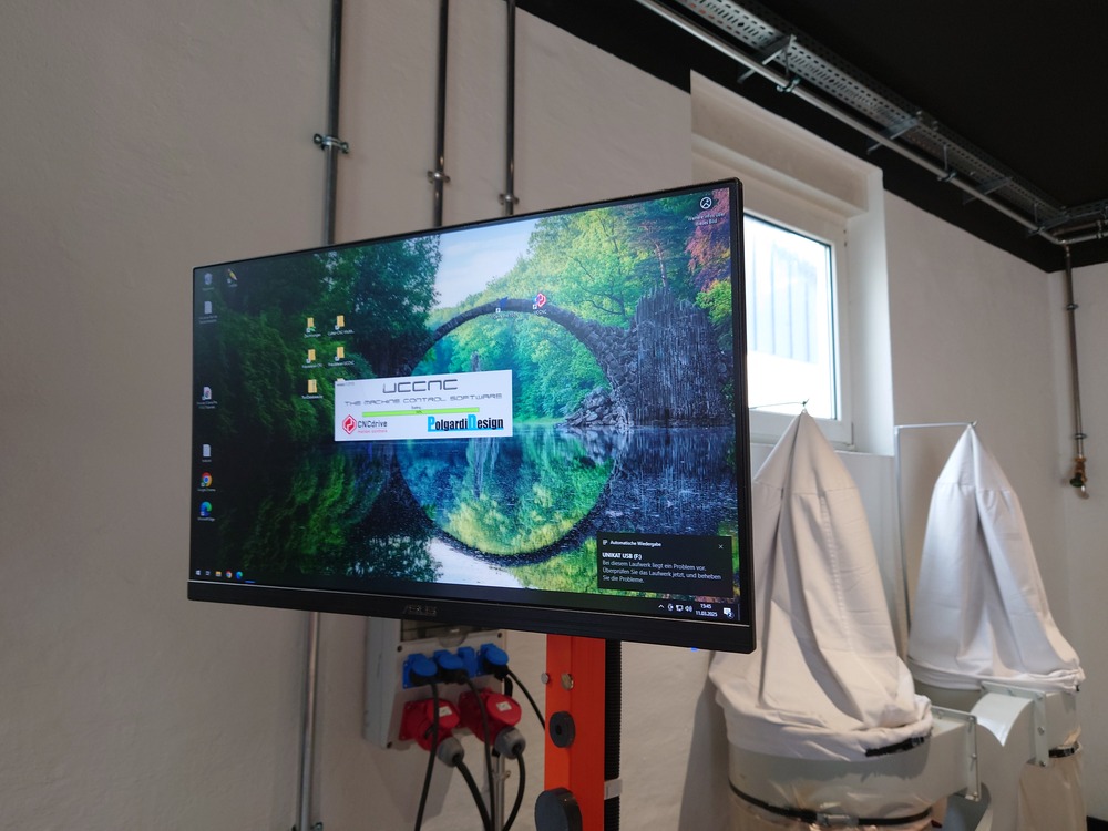
For starting the milling @CNC-Multitool, we need to turn on the machine controller and then turns on the PC.
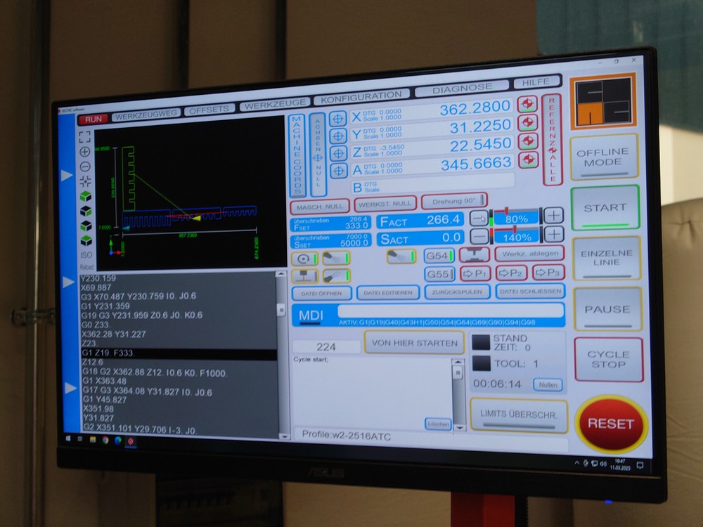
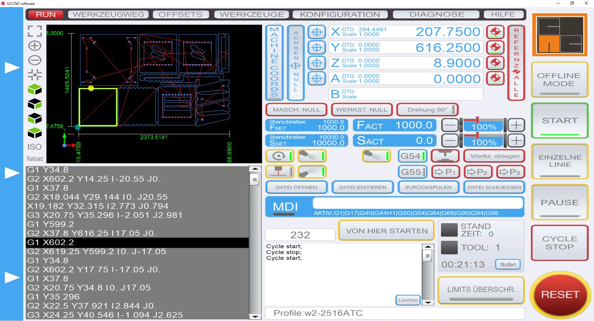
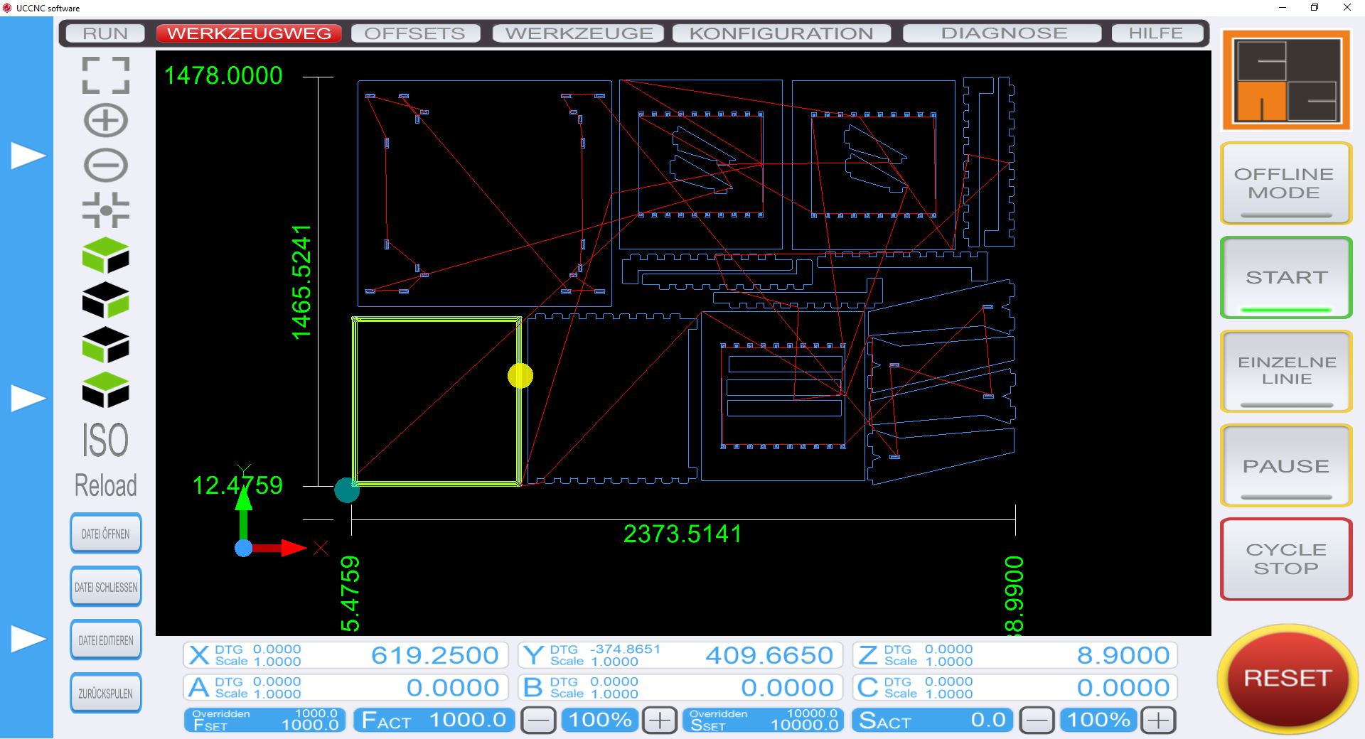
The software
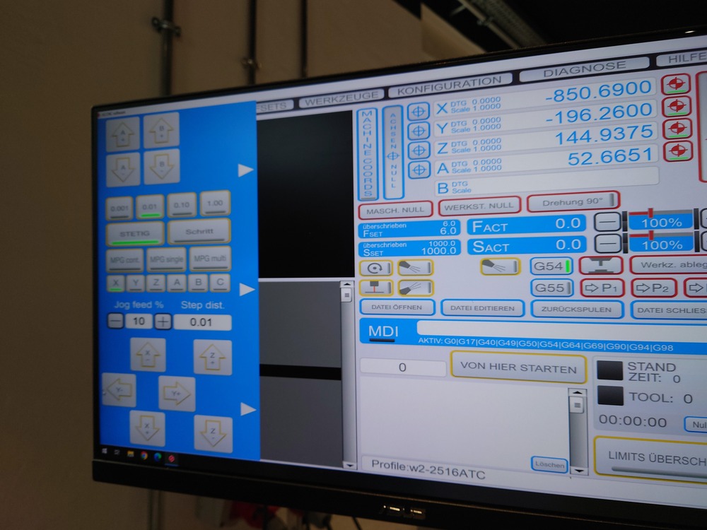 The manual control panel
Then Start the ‘UCCNC’ software and DON’T CLOSE THE SMALL POP UP WINDOW.
Now in the UI, use ‘Referenz Alle’ to Home the CNC.
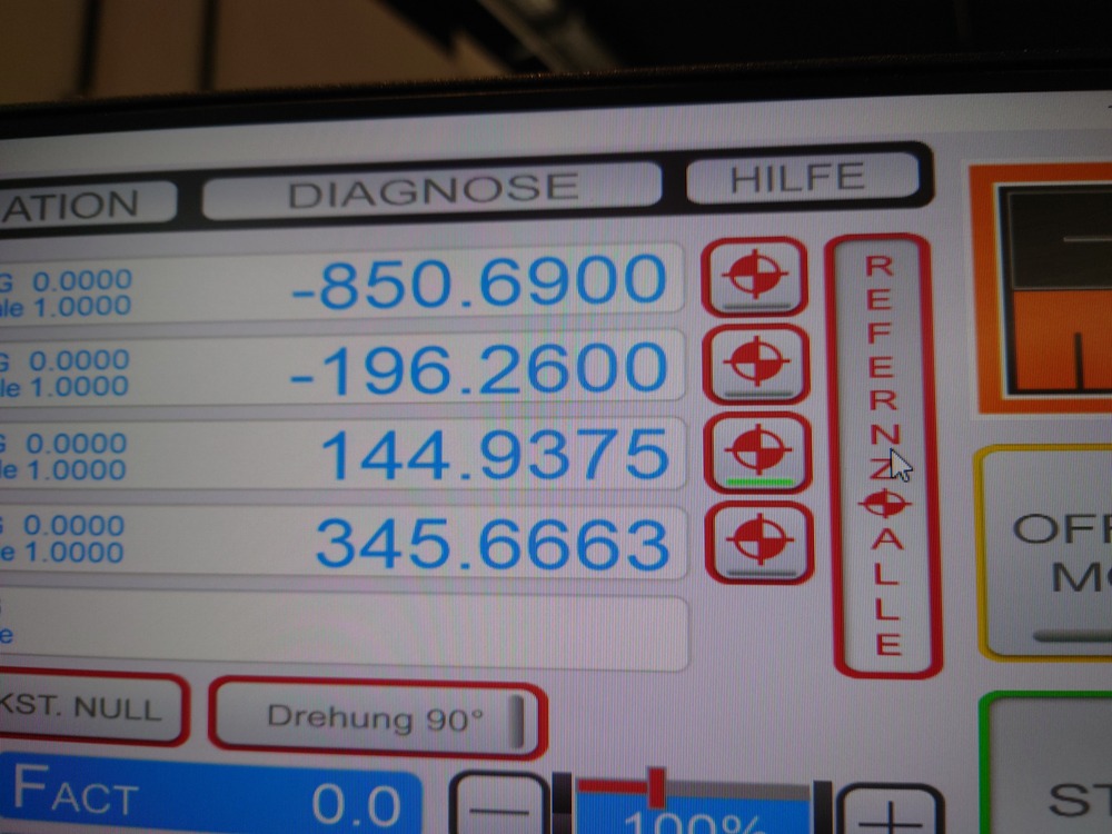
Next Set the work-zero (the Cross Hairs next to the axis buttons).
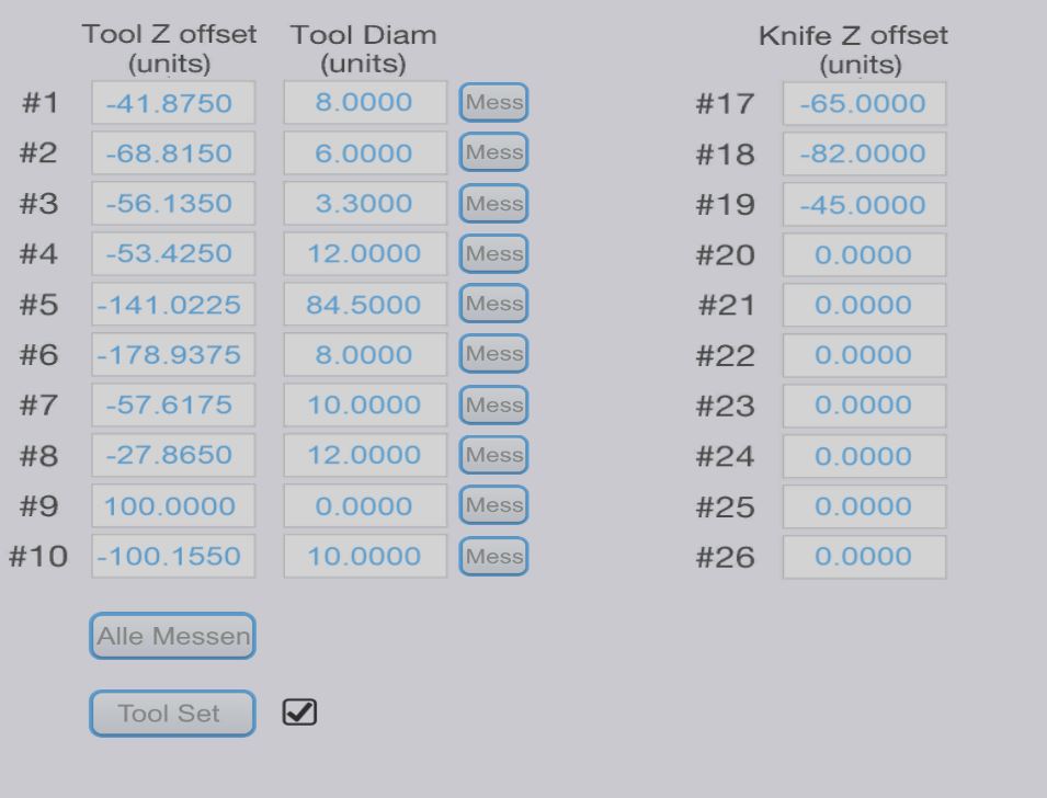
Check, that the tool settings are like your settings in Fusion:
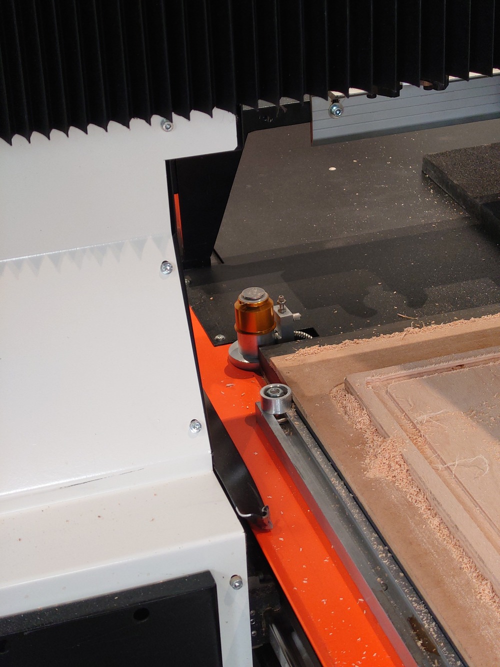
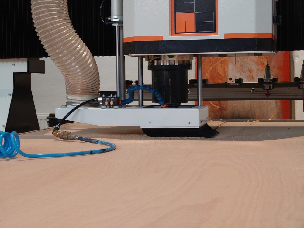
Before loading the GCODE, we need to measure the tool and like the Carvera, this CNC can automatically measure the tool-length and also activate all vacuums (table, suction).
Measure tool button


buttons on the side are for vacuum and suction.
Then open the GCODE File and start milling.
Note
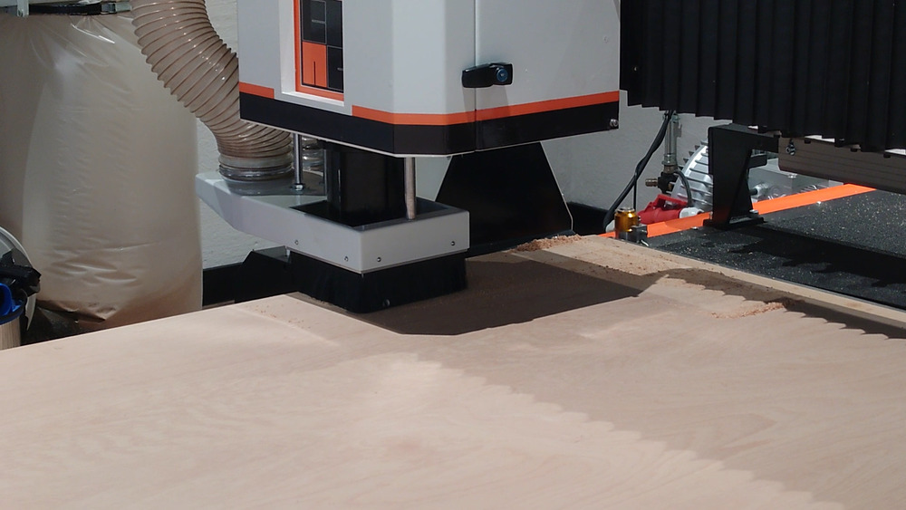
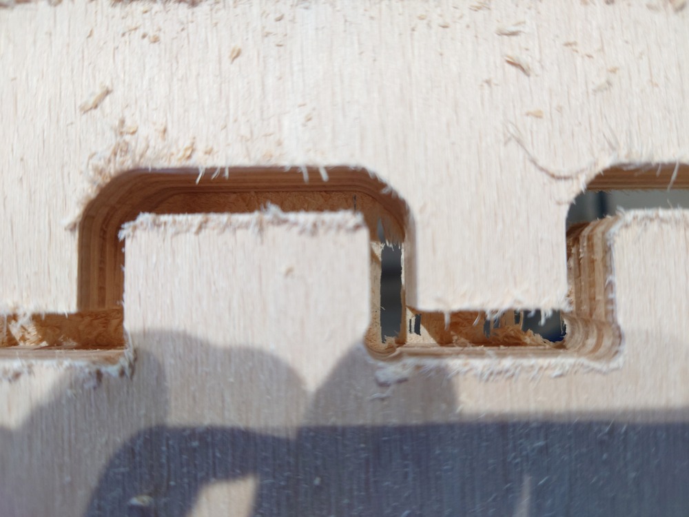
In this case I also used pressured air to clean out the chips in the milling area because this helped with the edges afterwards.
The edges were not that clean (spiral ridge was on the edge of the wood) when the chips are in the way and the vacuum was not strong enough to clean out all the lose chips.
Result
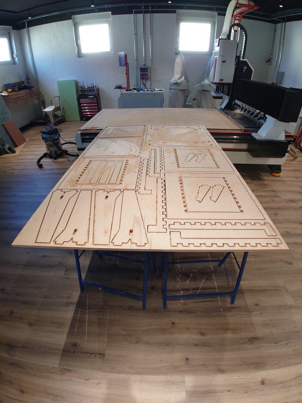
And here the files from milling:
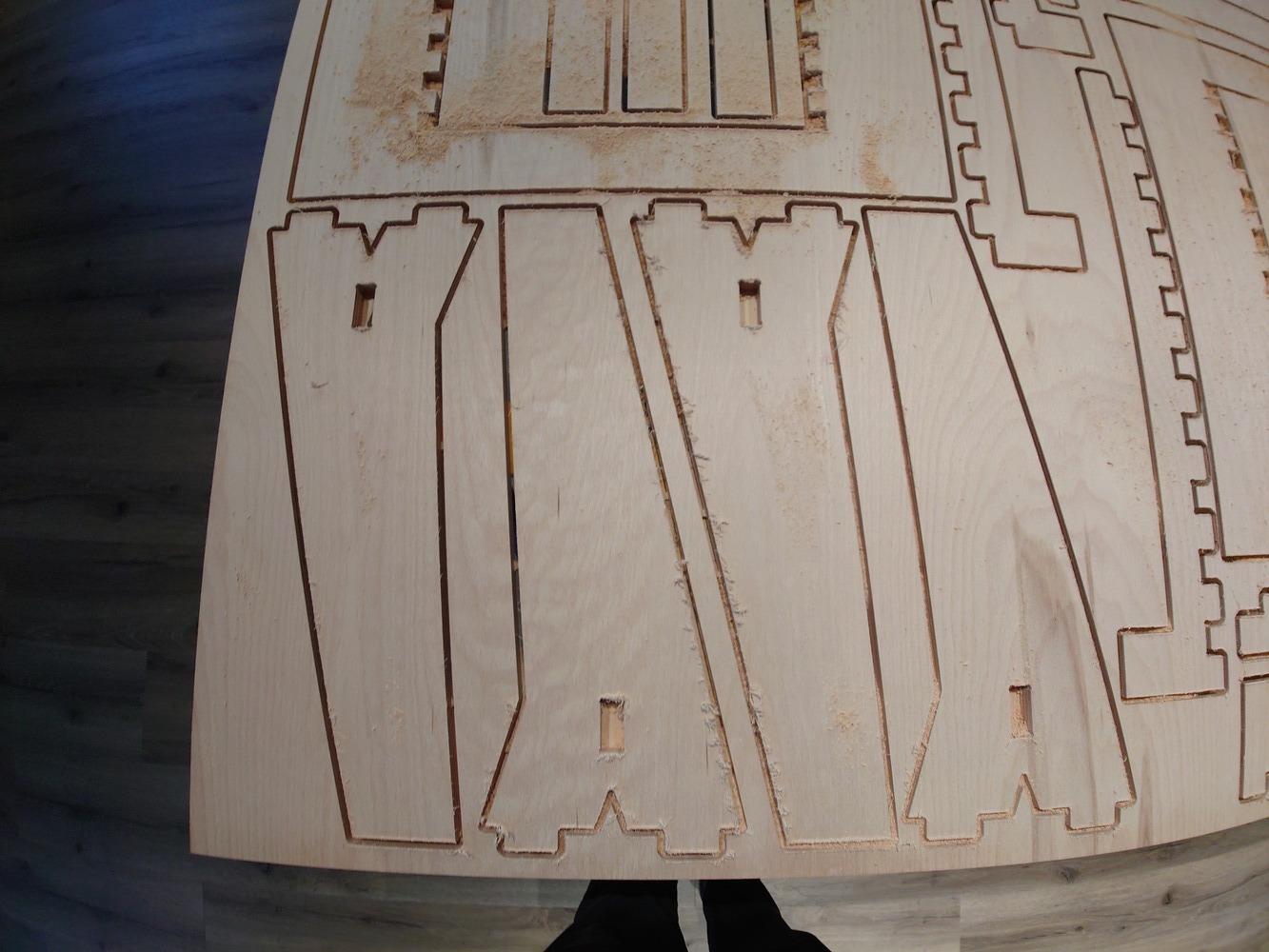
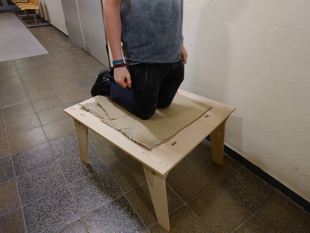
On this side, the wood was a bit thicker than I set in the model of the workpiece, but is was less then 1mm so it was no big problem.
The bigger problem was, that the press fit connections where a bit to hard to press into -.- …
And so I decided, that the Table is good enough unfortunately ._.
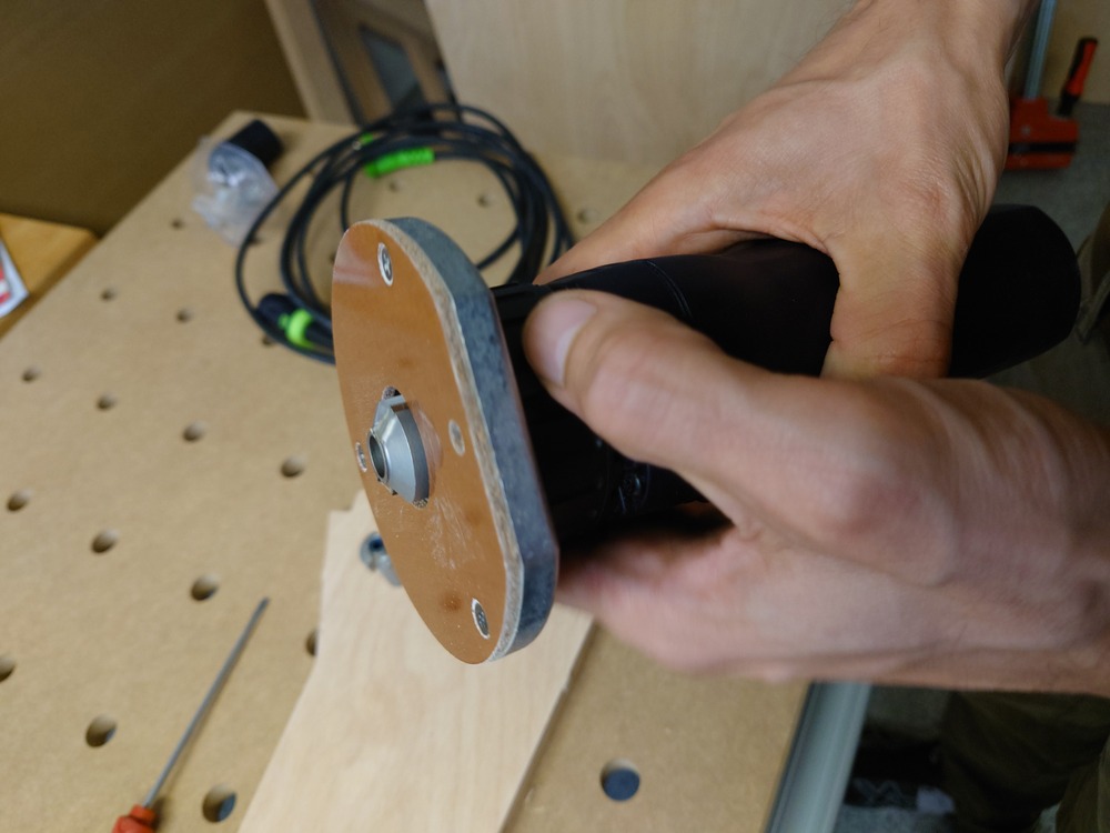
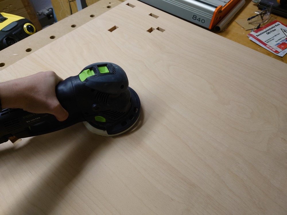
Post Process
In post-processing I used a router to make clean edges and sanded the surfaces:
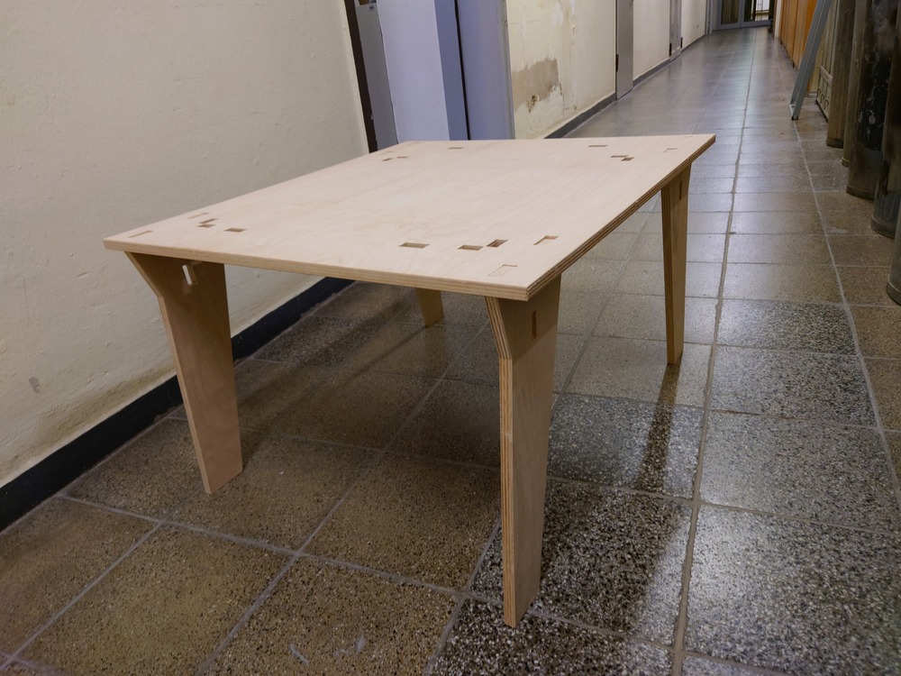
Assemble
Assembling was now only to put the legs into the table with a wood hammer.
7.3.4. Result
7.3.5. Design Files
7.4. Notes
7.4.1. Tips
don’t forget dog-bones for fixtures
use minimal dog-bones -> place middle point of circle on a line 45deg. in the corner with its radius to the corner
plan screw in CAM - Programm
make a model in laser-cut
test-print joints
plan screw in CAM - Programm
For fixing:
(tape)
vacuum table (not for small parts)
tabs
straight flute also available
high chip load
easy to sharpen
the more cutting edges, the bigger the mill
posidrive vs philips head screw -> posidrive the sides are parallel -> philips the side is conical!
small parts screw down
clamping is very important -> clamp to far out -> wood may flex -> clamp to far in -> machine may drive into it -> take into account
wood is probably not exactly flat and has tension in it
screw
on tension -> may bend if cut -> more tabs, more screws
caliper -> don’t save money on them (helios-preisser in Germany)
chips on mill -> use something like WD40 on the mill against alu-particle -> also mill conducts heat better
7.4.2. Freecad
change units (mm, mm/s, etc.) left in the project itself when selecting the project
selecting material
7.4.3. FerdiAcademy
@ CNC-Multitool
7.4.4. Material
plywood
2500mmx1500mmx18mm
quality 1-2
6 mm milling bit
0.01 mm steps can depend for a good fit
wood not same thickness everywhere
z=0.0 auf der Unterseite (Empfehlenswert)
7.4.5. MAKE SOMETHING BIG
Andrew Klein - twin turbo wise - in-klein
magnetic vice
https://www.youtube.com/@sliptonic/videos
7.4.6. Mills an Drills
extra mill for roughing (with rills in flute)
depend on material cut
HSS (high speed steel) mill -> alu and wood, plastic
carbite mill (dark-ish) -> harder (steel, etc.)
flute length -> wegen abnutzung
strong ridgit
not just tip, as loong as needed
flute number
radius
as much material as possible
stability