11. Networking and Communications - Week 11
11.1. Assignments
Networking and Communications
group assignment
send a message between two projects
individual assignment
design, build, and connect wired or wireless node(s)
with network or bus addresses and local input &/or output device(s)
11.2. Group Assignment
11.2.1. Gauntlet-Keyboard
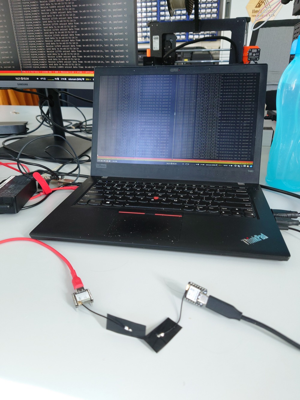
For the group assignment, me and Jakob wanted to let our project communicate together.
The Idea was to control my LED matrix with Jakobs IMU and to activate his LEDs with my touch-inputs.
We both use the ESP32 MCUs and so we wanted to try out our RF-Modules because of our projects (I want optionally let my keyboard-modules communicate with each other wirelessly).
And there we choose to try out the ESPNOW protocol:
used with Bluetooth of Wifi
lays above the Link layer (so in the same Layer as IP)
also supports encryption with AES and key exchange an ECDH
For the implementation, we used the ESP-IDF.
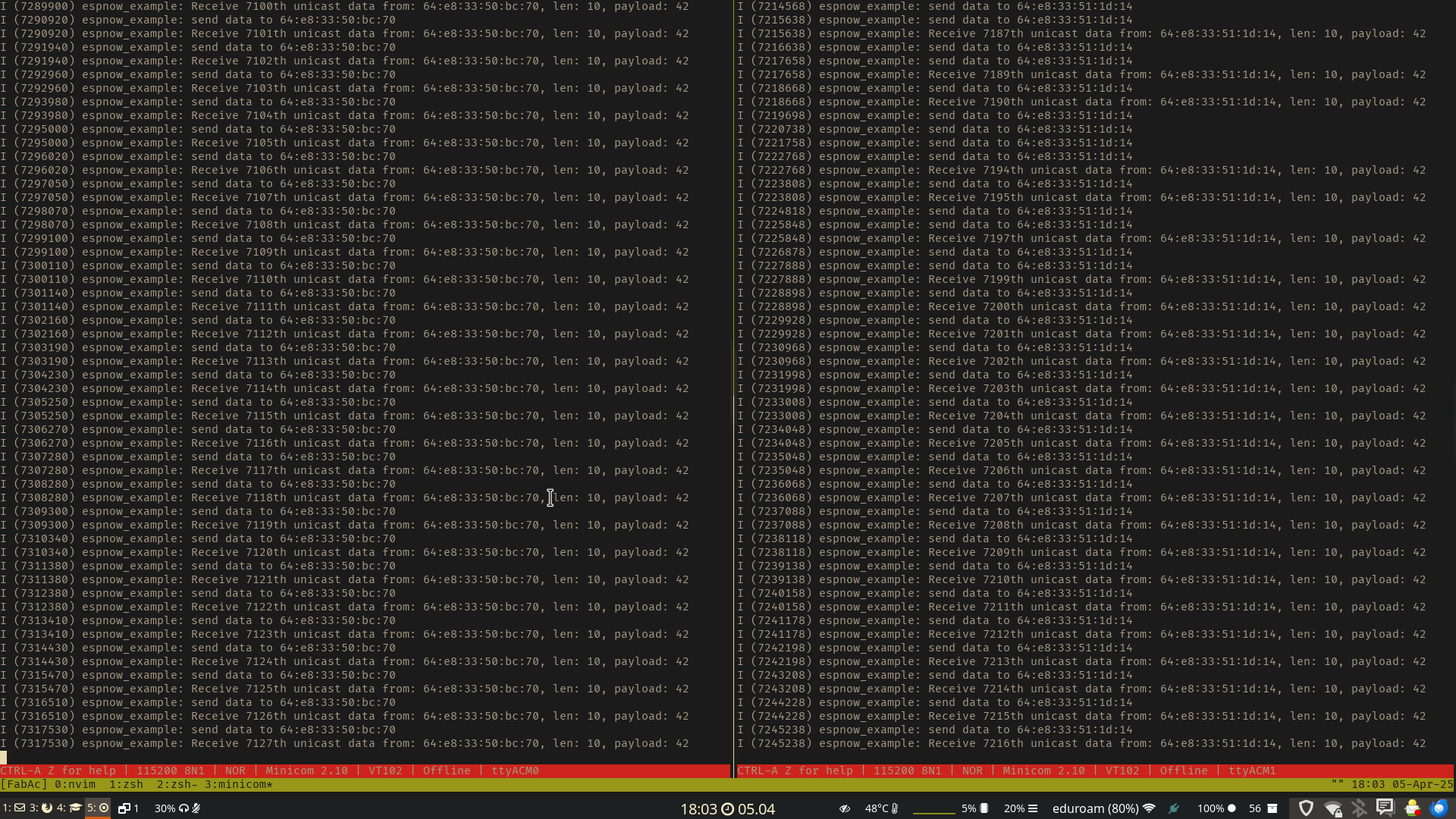
First we tested out the basic example, where just 2 ESPs send each other random data.
TL;DR the code works like this:
Initialises the Wifi (setup for the link-layer)
Initialises ESPNOW stack
registers callbacks for received and send messages (called whenever a message is received/send)
adds a peer to its list (first only the broadcast-channel)
Starts receiving and sending task
initially sends a message to the broadcast-channel on link-layer
does it, until it receives an answer, then adds the device to the list
continues receiving and sending to this device
Note
They use a queue to add events to on every callback call, which then gets popped in the receiving and sending task.
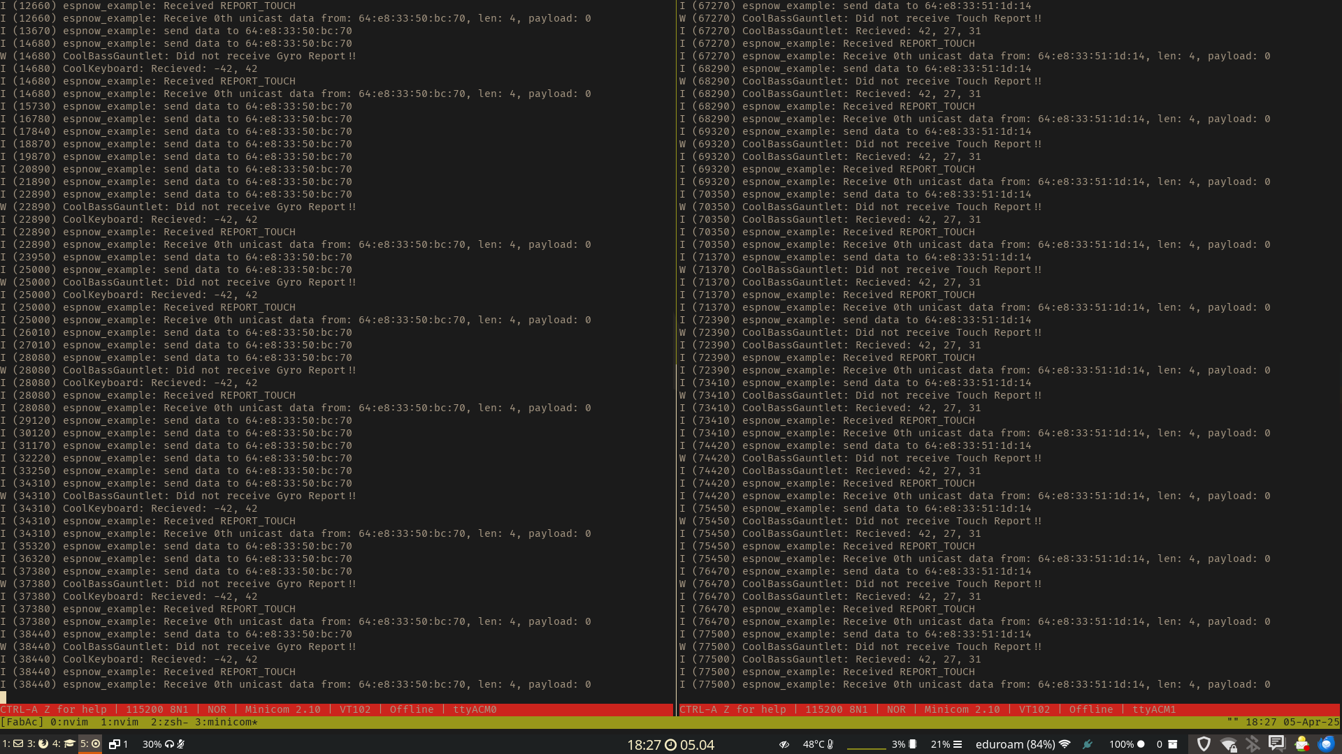
We then simplified the code and added our parts to it to control the LEDs and send Key-presses:
We adjusted:
the parse and prepare function
/* Parse received ESPNOW data. */
// The received content `data` is written into a data structure `seq`.
// Postprocessing of received data.
int espnow_data_parse(uint8_t *data, uint16_t data_len) {


  ReportData rep_dat;
  memcpy(rep_dat.data, data, data_len);
  int ret = process_report(rep_dat);

  if (ret != 1) {
    ESP_LOGE(TAG, "Error on processing data");
    return -1;
  }

  ESP_LOGI(TAG, "Received %s",
  rep_dat.Report.type == REPORT_GYRO ? "REPORT_GYRO" : "REPORT_TOUCH");

  return 1;
}

/* Prepare ESPNOW data to be sent. */
// Preprocessing of data to be sent. `send_param` is the output of this
// function.
void espnow_data_prepare(espnow_send_param_t *send_param) {

      ReportData tmp_rep_dat = gather_report();
      memcpy(send_param->buffer, &tmp_rep_dat, sizeof(ReportData));
}
and then implemented the
process_reportandgather_report-functions
keyboard.h
int process_report(ReportData rep) {
      // no roll

      if (rep.Report.type != REPORT_GYRO) {
    ESP_LOGW(TOUCH_TAG, "Did not receive Gyro Report!!");
    // return -1;
  };

      ReportGyro rep_to;
      memcpy(rep_to.data, rep.Report.report, sizeof(ReportGyro));

  ESP_LOGI(TOUCH_TAG, "Recieved: %d, %d", rep_to.Entries.roll,
                      rep_to.Entries.pitch);

  switch (rep_to.Entries.pitch) {
  case 42 ... 127:
        gpio_set_level(LED_V0, 1);
    gpio_set_level(LED_V1, 0);
    gpio_set_level(LED_V2, 0);
    break;
      case -41 ... 41:
        gpio_set_level(LED_V0, 0);
    gpio_set_level(LED_V1, 1);
    gpio_set_level(LED_V2, 0);
    break;
      case -128 ... - 42:
        gpio_set_level(LED_V0, 0);
    gpio_set_level(LED_V1, 0);
    gpio_set_level(LED_V2, 1);
    break;
      default:
        ESP_LOGE(TOUCH_TAG, "UNREACHABLE switch process");
  }

  return 1;
};

ReportData gather_report() {
      ReportTouch rep_gy;

      for (int i = 0; i < NUM_OF_TOUCHPADS; i++) {
               uint32_t touch_value = 0;
               uint8_t scaled_value = 0;
               touch_pad_read_raw_data(button[i], &touch_value);
    printf("T%d: [%4" PRIu32 "] ", button[i], touch_value);
    scaled_value =
                   (touch_value - TOUCH_DEFAULT_LEVEL) * UINT8_MAX / TOUCH_MAX_LEVEL;

    switch (i) {
               case 0:
                 rep_gy.Entries.first = scaled_value;
      break;
               case 1:
                 rep_gy.Entries.second = scaled_value;
      break;
               case 2:
                 rep_gy.Entries.third = scaled_value;
      break;
               default:
                 ESP_LOGE(TOUCH_TAG, "UNREACHABLE switch gather");
    }
    printf("\n");
  }

  ReportData rep;
      memcpy(rep.Report.report, rep_gy.data, sizeof(ReportTouch));
  rep.Report.type = REPORT_TOUCH;
  return rep;
};
gauntlet.h
int process_report(ReportData rep) {

      if (rep.Report.type != REPORT_TOUCH) {
    ESP_LOGW(GAUNTLET_TAG, "Did not receive Touch Report!!");
    // return -1;
  };

      ReportTouch rep_to;
      memcpy(rep_to.data, rep.Report.report, sizeof(ReportTouch));

  ESP_LOGI(GAUNTLET_TAG, "Recieved: %d, %d, %d", rep_to.Entries.first,
                      rep_to.Entries.second, rep_to.Entries.third);

  led_strip_set_pixel(led_strip, 0, rep_to.Entries.first, rep_to.Entries.first,
                                            rep_to.Entries.first);
  led_strip_set_pixel(led_strip, 1, rep_to.Entries.second,
                                            rep_to.Entries.second, rep_to.Entries.second);
  led_strip_set_pixel(led_strip, 2, rep_to.Entries.third, rep_to.Entries.third,
                                            rep_to.Entries.third);
  led_strip_refresh(led_strip);

  return 1;
};

ReportData gather_report() {

      if (pitch < 127) {
    pitch++;
  } else {
    pitch = -128;
  }

  ReportGyro rep_gy;
      rep_gy.Entries.pitch = pitch;
  rep_gy.Entries.roll = 0; // Roll stays always zero for now.

  ReportData rep;
      memcpy(rep.Report.report, rep_gy.data, sizeof(ReportGyro));
  rep.Report.type = REPORT_GYRO;
  return rep;
};
And for addressing the devices, we needed our MAC Adress of the WiFi card, we used this to find it out:
uint8_t mac[6] = { 0, 0, 0, 0, 0, 0 };
esp_wifi_get_mac(WIFI_IF_STA, mac);
ESP_LOGI(TAG, "MAC: " MACSTR "", MAC2STR(mac));
and then had this preprocessor definition declared in each header:
// 0x64, 0xE8, 0x33, 0x50, 0xbc, 0x70 // Jakob
static uint8_t s_peer_mac[ESP_NOW_ETH_ALEN] = {
    0x64, 0xE8, 0x33, 0x51, 0x1d, 0x14 // Niclas
};
Then for building flashing, we used:
idf.py set-target eps32s3
idf.py -p /dev/ttyACM0 flash
I also needed to download the LED Strip library for controlling the Neopixel-LEDs.
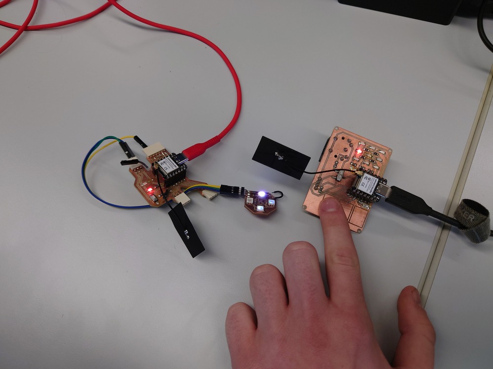
Then we added out sensors and it blinked :D
11.2.2. MIoTy/TSUNB Workshop
11.2.2.1. Protocol
used for LPWAN(Low-power WAN)/LTN(Low transmission networks) -> long range
telegramm splitting
868MHz
needs a base-station for communication
Robust:
recover from 50% loss
pseudo-random frequency an time-offset
FEC CR: 1/3
11.2.2.2. Workshop
MQTT as a software-protocol
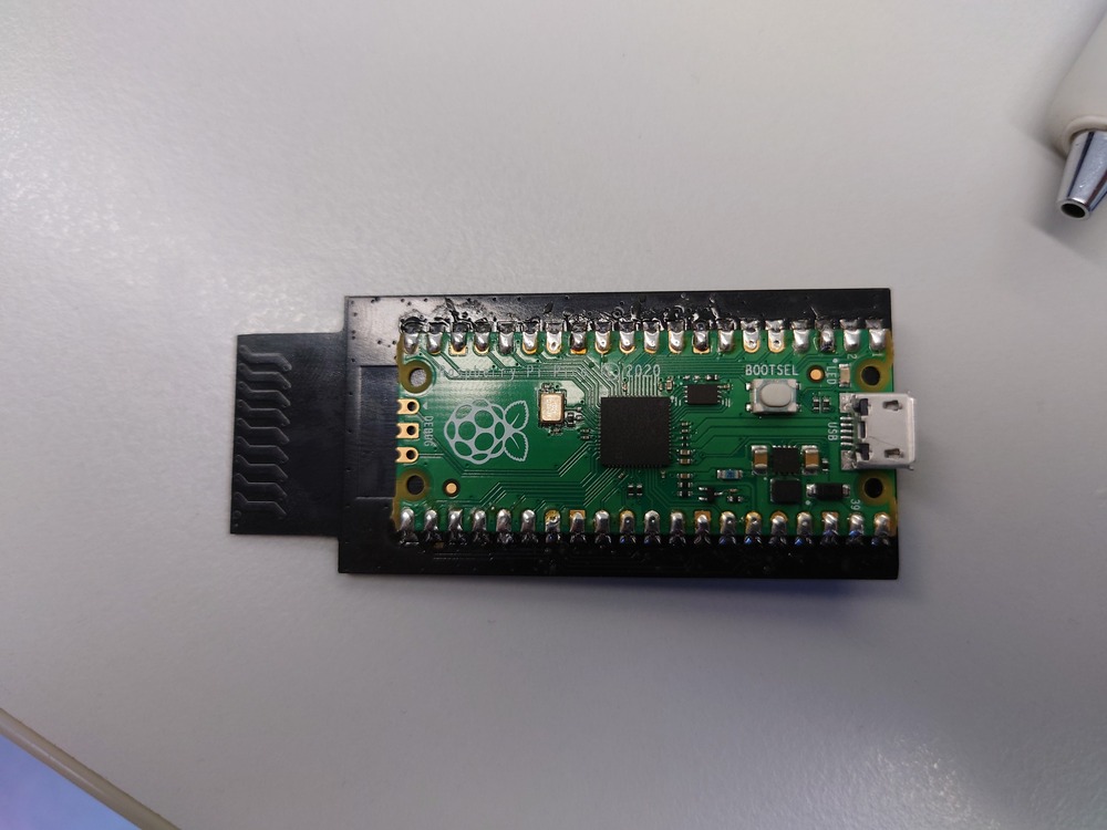
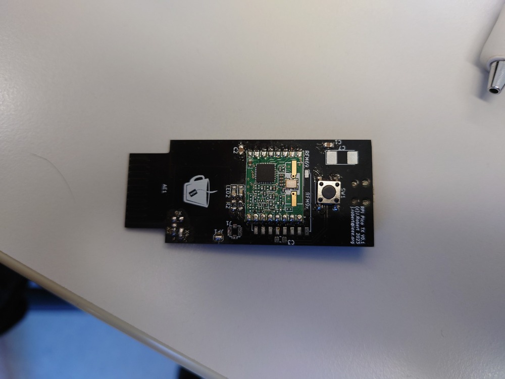
TX Chip: hoperf 69HW
we use an inverted F antenna
connection to antenna as short as possible to reduce interference -> don’t wont to have trace as antenna
we used a h-bridge because we could adjust the impedance of the antenna afterwards, we also jut the antenna in our case
Circuit for power compensation for 3.3v when receiving Signal filter high-frequency disturbance
100nF immer gut gegen disturbance
SPI MOSI == RX
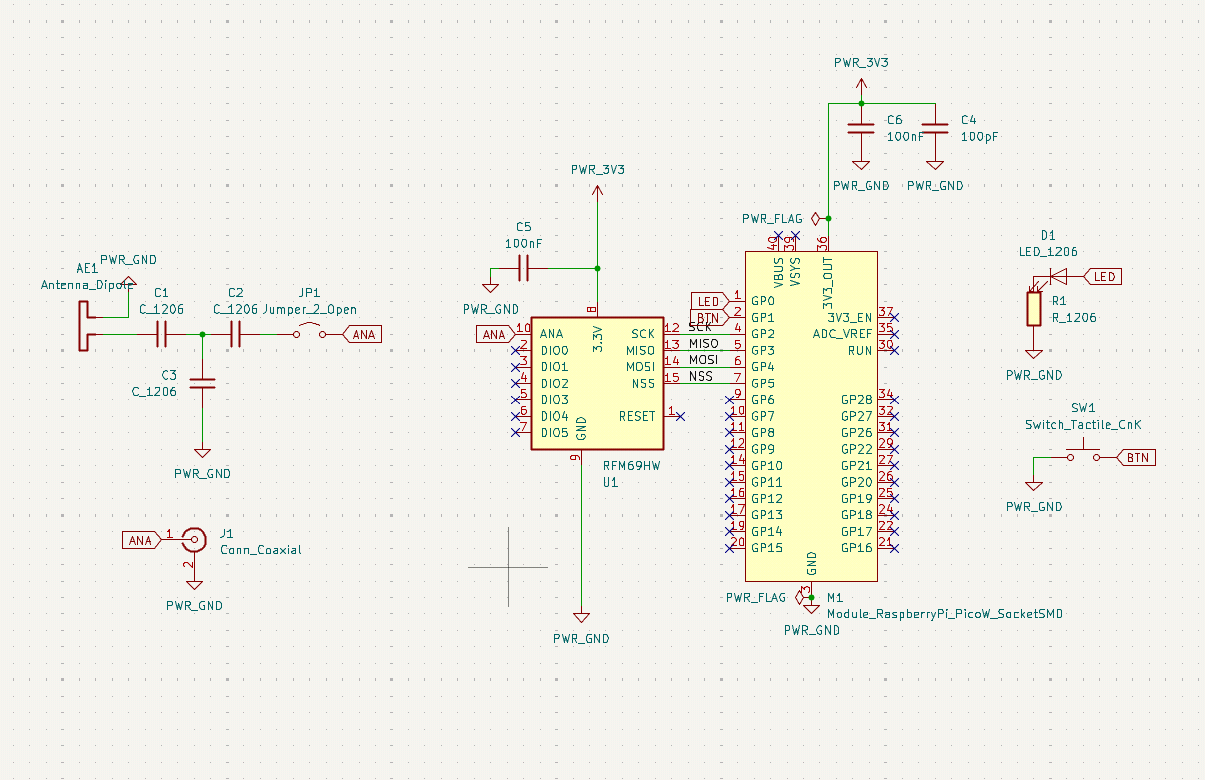
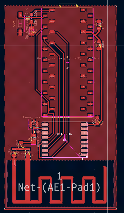
Schematics
11.3. Individual Assignment
For my individual Assignment I wanted to build little keyboard-modules and let them communicate their key presses to the main module (connected to the pc) and receive an led, that should be activated. Optionally, if I find time, I would implement a little usb midi device to play with the keys.
11.3.1. I2C vs SPI
First I want to compair I2C and SPI to choose, which one I use for communication.
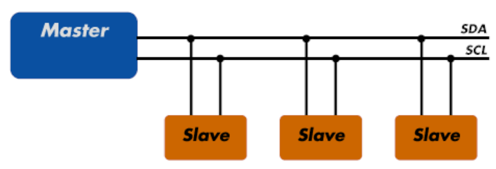
I2C
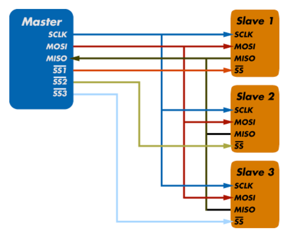
SPI
Comparison
Feature |
I2C |
SPI |
|---|---|---|
Wires |
2 |
4+ |
Speed |
slow (100kbps) but faster modes availbe (up to 5Mbps) |
no maximum speed from protocol (100Mbps achieved) |
Power |
more then SPI |
less then I2C |
Noise |
less susceptible |
more susceptible |
Main node |
Multi main protocol -> arbitrary number of main devices and many sub devices |
single main protocol |
Verification |
uses ACKs |
no verification in protocol |
Messages |
I2C communication uses messages that are separated into frames. A 7- or 10-bit frame routes the message and data is transmitted in 8-bit frames separated by acknowledge bits that verify receipt of the data |
SPI communication works using shift registers. Messages can be 8-bit, but twelve or sixteen-bit data transmissions are also possible. |
Dupex |
Half duplex mode – individual wires can communicate data in both directions, but not at the same time |
Full duplex mode – individual wires can simultaneously communicate data in both directions |
Conclusion
I’m goint to choose I2C because I don’t need more pins in the future for an arbitrary number of modules and I don’t need high speeds and that low power.
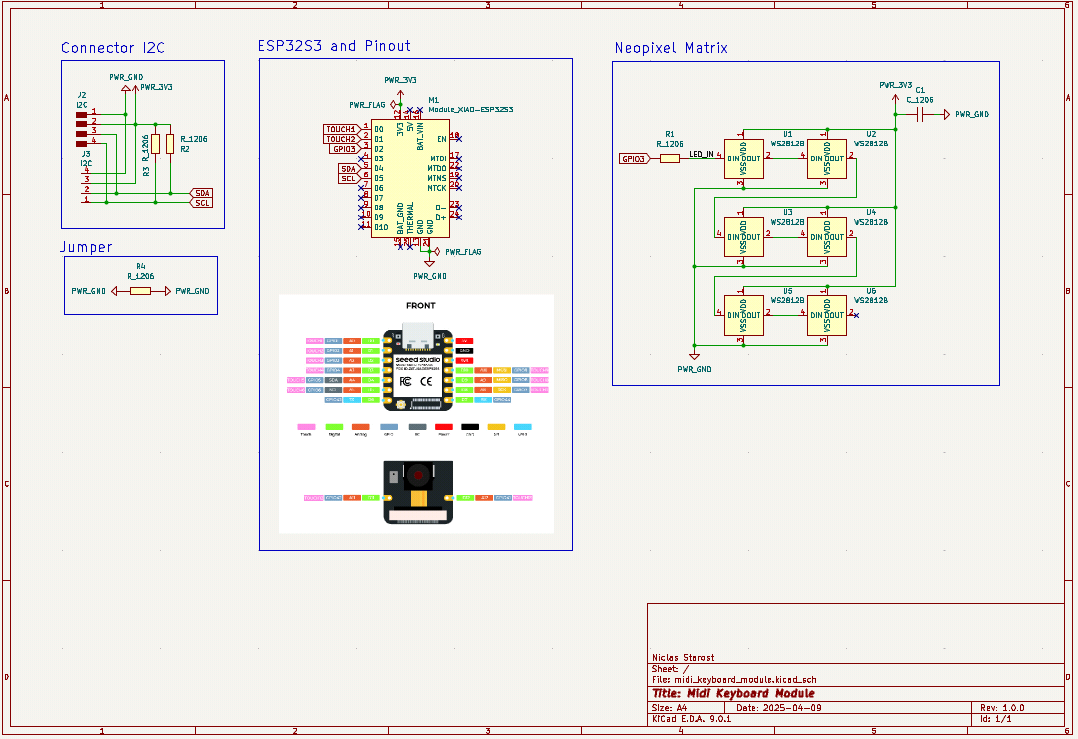
11.3.2. Designing the PCB
I also wanted to test the WS2812b LEDs because most likely I’m going to use them in my final project.
for I2C I need to pull-up the
SDAandSCLpins to ensure, they are usually high, if nothing is sendresistor size depends on the speed you want to reach (here a small calculation for deciding the resistance value)
I simply chose 1kOhm
Schematics
Traces
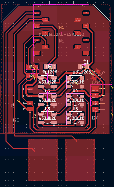
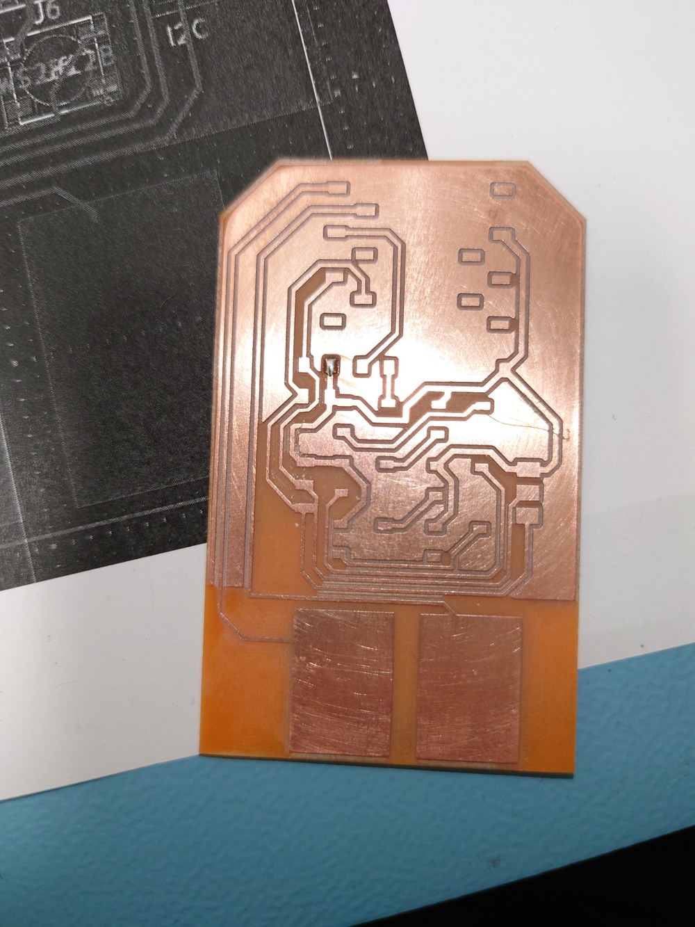
11.3.3. Building it
I milled to of them, but I unfortunately made one mistake on generating the GCODE and on using the ground plane I forgot to use Thermal Reliefs:
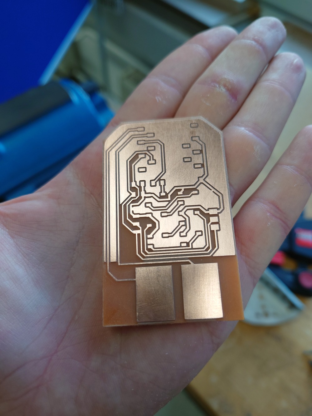
If you look on the big ground plane in the middle, it is sometimes connected to the traces, which should not have happened.
This was because I used 0.4mm tool radius for our 0.2mm V-Bit >.<
But It could be cut with relative ease:
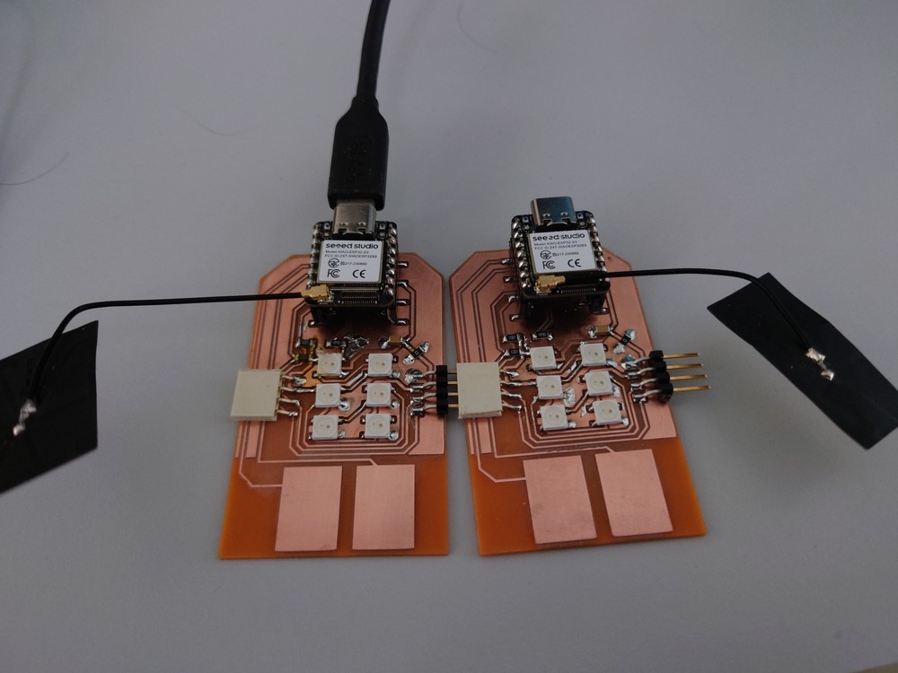
But After that, I soldered everything and it came out quite nicely:
Test code (based on this example using this library)
/*
 * SPDX-FileCopyrightText: 2023-2024 Espressif Systems (Shanghai) CO LTD
 *
 * SPDX-License-Identifier: Unlicense OR CC0-1.0
 */
#include <stdio.h>
#include "freertos/FreeRTOS.h"
#include "freertos/task.h"
#include "led_strip.h"
#include "esp_log.h"
#include "esp_err.h"

// Set to 1 to use DMA for driving the LED strip, 0 otherwise
// Please note the RMT DMA feature is only available on chips e.g. ESP32-S3/P4
#define LED_STRIP_USE_DMA  0

#if LED_STRIP_USE_DMA
// Numbers of the LED in the strip
#define LED_STRIP_LED_COUNT 256
#define LED_STRIP_MEMORY_BLOCK_WORDS 1024 // this determines the DMA block size
#else
// Numbers of the LED in the strip
#define LED_STRIP_LED_COUNT 6
#define LED_STRIP_MEMORY_BLOCK_WORDS 0 // let the driver choose a proper memory block size automatically
#endif // LED_STRIP_USE_DMA

// GPIO assignment
#define LED_STRIP_GPIO_PIN  3

// 10MHz resolution, 1 tick = 0.1us (led strip needs a high resolution)
#define LED_STRIP_RMT_RES_HZ  (10 * 1000 * 1000)

static const char *TAG = "example";

led_strip_handle_t configure_led(void)
{
        // LED strip general initialization, according to your led board design
        led_strip_config_t strip_config = {
        .strip_gpio_num = LED_STRIP_GPIO_PIN, // The GPIO that connected to the LED strip's data line
        .max_leds = LED_STRIP_LED_COUNT,      // The number of LEDs in the strip,
        .led_model = LED_MODEL_WS2812,        // LED strip model
        .color_component_format = LED_STRIP_COLOR_COMPONENT_FMT_GRB, // The color order of the strip: GRB
        .flags = {
            .invert_out = false, // don't invert the output signal
        }
        };

        // LED strip backend configuration: RMT
        led_strip_rmt_config_t rmt_config = {
        .clk_src = RMT_CLK_SRC_DEFAULT,        // different clock source can lead to different power consumption
        .resolution_hz = LED_STRIP_RMT_RES_HZ, // RMT counter clock frequency
        .mem_block_symbols = LED_STRIP_MEMORY_BLOCK_WORDS, // the memory block size used by the RMT channel
        .flags = {
            .with_dma = LED_STRIP_USE_DMA,     // Using DMA can improve performance when driving more LEDs
        }
        };

        // LED Strip object handle
        led_strip_handle_t led_strip;
        ESP_ERROR_CHECK(led_strip_new_rmt_device(&strip_config, &rmt_config, &led_strip));
    ESP_LOGI(TAG, "Created LED strip object with RMT backend");
    return led_strip;
}

void app_main(void)
{
        led_strip_handle_t led_strip = configure_led();
        bool led_on_off = false;

        ESP_LOGI(TAG, "Start blinking LED strip");
    while (1) {
        if (led_on_off) {
            /* Set the LED pixel using RGB from 0 (0%) to 255 (100%) for each color */
            for (int i = 0; i < LED_STRIP_LED_COUNT; i++) {
                                 ESP_ERROR_CHECK(led_strip_set_pixel(led_strip, i, 5, 5, 5));
                             }
            /* Refresh the strip to send data */
            ESP_ERROR_CHECK(led_strip_refresh(led_strip));
            ESP_LOGI(TAG, "LED ON!");
        } else {
            /* Set all LED off to clear all pixels */
            ESP_ERROR_CHECK(led_strip_clear(led_strip));
            ESP_LOGI(TAG, "LED OFF!");
        }

        led_on_off = !led_on_off;
        vTaskDelay(pdMS_TO_TICKS(500));
    }
}
11.3.4. Using I2C
I tried to work with it and implemented a little thing but it didn’t worked and unfortunately I didn’t had enough time to find my bug…
Slave Code
/*
 * SPDX-FileCopyrightText: 2023 Espressif Systems (Shanghai) CO LTD
 *
 * SPDX-License-Identifier: Unlicense OR CC0-1.0
   */
  // #include "driver/gpio.h"
#include "driver/i2c_slave.h"
#include "driver/i2c_types.h"
#include "driver/touch_pad.h"
#include "esp_log.h"
#include "freertos/FreeRTOS.h"
#include "freertos/idf_additions.h"
#include "freertos/task.h"
#include "led_strip.h"
#include "led_strip_types.h"
#include "sdkconfig.h"
#include <stdbool.h>
#include <stdint.h>
#include <stdio.h>
#include <string.h>

#define TOUCH_DEFAULT_LEVEL 20000
#define TOUCH_MAX_LEVEL 800000

#define DELAY 512

#define SCL_IO_PIN 6
#define SDA_IO_PIN 5
#define I2C_FREQUENCY 100000
#define I2C_ADDR 0x58
#define PORT_NUMBER -1
#define LENGTH 48

#define TOUCH_BUTTON_NUM 2
#define TOUCH_CHANGE_CONFIG 0
#define TAG "I2C TEST"

#define LED_STRIP_GPIO_PIN 3
#define LED_STRIP_LED_COUNT 6
#define LED_STRIP_MEMORY_BLOCK_WORDS                                           \
    0 // let the driver choose a proper memory block size automatically

  // 10MHz resolution, 1 tick = 0.1us (led strip needs a high resolution)
#define LED_STRIP_RMT_RES_HZ (10 * 1000 * 1000)

  QueueHandle_t event_queue;

typedef enum { LED, TOUCH } EvtType;

typedef struct {
  uint8_t index;
  uint8_t intensity;
} LedTouchData;

typedef union {
  struct {
    EvtType type;
    LedTouchData led_data;
  } Evt;
  uint8_t data[8];
} Event;

static const touch_pad_t button[TOUCH_BUTTON_NUM] = {
    TOUCH_PAD_NUM1,
    TOUCH_PAD_NUM2,
};

typedef struct {
  i2c_slave_dev_handle_t i2c_handle;
  led_strip_handle_t led_handle;
} Handlers;

static bool i2c_slave_request_cb(i2c_slave_dev_handle_t i2c_slave,
                                 const i2c_slave_request_event_data_t *evt_data,
                                 void *arg) {
  return true;
}

static bool i2c_slave_receive_cb(i2c_slave_dev_handle_t i2c_slave,
                                 const i2c_slave_rx_done_event_data_t *evt_data,
                                 void *arg) {
  Event e;
  memcpy(e.data, evt_data, sizeof(Event));
  ESP_LOGI(TAG, "Received: index %d, intensity %d ", e.Evt.led_data.index,
           e.Evt.led_data.intensity);
  xQueueSend(event_queue, &e, DELAY);
  return true;
}

static void event_task(void *arg) {

  Handlers *handle = (Handlers *)arg;

  while (true) {
    Event evt;
    if (xQueueReceive(event_queue, &evt, 10) == pdTRUE) {
      if (evt.Evt.type == LED) {

        uint8_t intensity = evt.Evt.led_data.intensity;
        ESP_ERROR_CHECK(led_strip_set_pixel(handle->led_handle,
                                            evt.Evt.led_data.index, intensity,
                                            intensity, intensity));
        /* Refresh the strip to send data */
        ESP_ERROR_CHECK(led_strip_refresh(handle->led_handle));
      }
    }

    uint32_t touch_value = 0;
    uint32_t write_len = 0;
    uint8_t scaled_value = 0;
    for (int i = 0; i < TOUCH_BUTTON_NUM; i++) {
      touch_pad_read_raw_data(button[i], &touch_value); // read raw data.
      scaled_value =
          (touch_value - TOUCH_DEFAULT_LEVEL) * UINT8_MAX / TOUCH_MAX_LEVEL;
      Event t_evt = {.Evt.type = TOUCH,
                     .Evt.led_data = {.intensity = i, .index = scaled_value}};
      uint8_t *data = &t_evt.data[0];
      // esp_err_t i2c_slave_write(i2c_slave_dev_handle_t i2c_slave, const
      // uint8_t *data, uint32_t len, uint32_t *write_len, int timeout_ms);
      ESP_ERROR_CHECK(i2c_slave_write(
          handle->i2c_handle, data, (uint32_t)sizeof(Event), &write_len, 1000));
      if (write_len == 0) {
        ESP_LOGE(TAG, "Write error or timeout");
        break;
      }
    }
  }
}

led_strip_handle_t configure_led(void) {
  // LED strip general initialization, according to your led board design
  led_strip_config_t strip_config = {
      .strip_gpio_num = LED_STRIP_GPIO_PIN, // The GPIO that connected to the
                                            // LED strip's data line
      .max_leds = LED_STRIP_LED_COUNT,      // The number of LEDs in the strip,
      .led_model = LED_MODEL_WS2812,        // LED strip model
      .color_component_format =
          LED_STRIP_COLOR_COMPONENT_FMT_GRB, // The color order of the strip:
                                             // GRB
      .flags = {
          .invert_out = false, // don't invert the output signal
      }};

  // LED strip backend configuration: RMT
  led_strip_rmt_config_t rmt_config = {
      .clk_src = RMT_CLK_SRC_DEFAULT, // different clock source can lead to
                                      // different power consumption
      .resolution_hz = LED_STRIP_RMT_RES_HZ, // RMT counter clock frequency
      .mem_block_symbols =
          LED_STRIP_MEMORY_BLOCK_WORDS, // the memory block size used by the
                                        // RMT channel
      .flags = {
          .with_dma =
              0, // Using DMA can improve performance when driving more LEDs
      }};

  // LED Strip object handle
  led_strip_handle_t led_strip;
  ESP_ERROR_CHECK(
      led_strip_new_rmt_device(&strip_config, &rmt_config, &led_strip));
  ESP_LOGI(TAG, "Created LED strip object with RMT backend");
  return led_strip;
}

static void init_touch() {
  /* Denoise setting at TouchSensor 0. */
  touch_pad_denoise_t denoise = {
      /* The bits to be cancelled are determined according to the noise level.
       */
      .grade = TOUCH_PAD_DENOISE_BIT4,
      .cap_level = TOUCH_PAD_DENOISE_CAP_L4,
  };

  touch_pad_init();
  for (int i = 0; i < TOUCH_BUTTON_NUM; i++) {
    touch_pad_config(button[i]);
  }
  touch_pad_denoise_set_config(&denoise);
  touch_pad_denoise_enable();
  ESP_LOGI(TAG, "Denoise function init");
  /* Enable touch sensor clock. Work mode is "timer trigger". */
  touch_pad_set_fsm_mode(TOUCH_FSM_MODE_TIMER);
  touch_pad_fsm_start();
}

void app_main(void) {
  i2c_slave_config_t i2c_slv_config = {
      .i2c_port = PORT_NUMBER,
      .clk_source = I2C_CLK_SRC_DEFAULT,
      .scl_io_num = SCL_IO_PIN,
      .sda_io_num = SDA_IO_PIN,
      .slave_addr = I2C_ADDR,
      .send_buf_depth = 100,
  };
  // i2c_device_config_t dev_cfg = {
  //     .dev_addr_length = I2C_ADDR_BIT_LEN_7,
  //     .device_address = I2C_ADDR,
  //     .scl_speed_hz = I2C_FREQUENCY,
  // };
  i2c_slave_dev_handle_t i2c_handle;

  init_touch();
  led_strip_handle_t led_handle = configure_led();

  event_queue = xQueueCreate(16, sizeof(Event));
  if (!event_queue) {
    ESP_LOGE(TAG, "Creating queue failed");
    return;
  }

  ESP_ERROR_CHECK(i2c_new_slave_device(&i2c_slv_config, &i2c_handle));
  i2c_slave_event_callbacks_t cbs = {
      .on_receive = i2c_slave_receive_cb,
      .on_request = i2c_slave_request_cb,
  };
  Handlers handlers = {
      .i2c_handle = i2c_handle,
      .led_handle = led_handle,
  };
  i2c_slave_register_event_callbacks(i2c_handle, &cbs, NULL);
  xTaskCreate(event_task, "event_task", 1024 * 4, &handlers, 10, NULL);
}
11.3.5. Failures
in mods, I set the tool diameter to 0.4 (or I forgot to change it >.<) which resulted in some connected traces…
I had soldered a leg with 5V to ground which caused the chip to not boot ._.
I forgot the thermal relieve in the ground-plane but It worked out in the end
when compiling i2c with the esp-idf, i forgot to use the second version of the I2C implementation (with
CONFIG_I2C_ENABLE_SLAVE_DRIVER_VERSION_2=y)
11.3.6. USB MIDI
I also needed a midi interface for my final project so I tried out tinyUSB and there was an example from the ESP-IDF.
In this example code, I added a function:
void keypress_as_midi(void *args) {
      static uint8_t const cable_num = 0; // MIDI jack associated with USB endpoint
      static uint8_t const channel = 0;   // 0 for channel 1
      bool pressed = false;

      while (1) {
    for (int i = 0; i < NUM_OF_TOUCHPADS; i++) {
               uint32_t touch_value = 0;
               uint8_t scaled_value = 0;
               int note = 0;

               touch_pad_read_raw_data(button[i], &touch_value);
      printf("T%d: [%4" PRIu32 "] ", button[i], touch_value);

      switch (i) {
               case 0:
                 note = 24;
                 break;
               case 1:
                 note = 26;
                 break;
               }
      if (tud_midi_mounted()) {
                 if (touch_value > 3 * TOUCH_DEFAULT_LEVEL) {
                   uint8_t note_on[3] = {NOTE_ON | channel, note, 127};
                   tud_midi_stream_write(cable_num, note_on, 3);
                   pressed = true;

                 } else if (touch_value < 3 * TOUCH_DEFAULT_LEVEL && pressed) {
                   // Send Note Off for previous note.
                   uint8_t note_off[3] = {NOTE_OFF | channel, note, 0};
                   tud_midi_stream_write(cable_num, note_off, 3);
                   pressed = false;
                 }
               }
    }
    vTaskDelay(100);
  }
}

...

void app_main(void) {

...

  xTaskCreate(keypress_as_midi, "keypress_as_midi", 8 * 1024, NULL, 5, NULL);
}
Master Code
/*
 * SPDX-FileCopyrightText: 2023 Espressif Systems (Shanghai) CO LTD
 *
 * SPDX-License-Identifier: Unlicense OR CC0-1.0
 */
// #include "driver/gpio.h"
#include "driver/i2c_master.h"
#include "driver/i2c_types.h"
#include "driver/touch_pad.h"
#include "esp_log.h"
#include "freertos/FreeRTOS.h"
#include "freertos/idf_additions.h"
#include "freertos/task.h"
#include "led_strip.h"
#include "led_strip_types.h"
#include "sdkconfig.h"
#include <stdbool.h>
#include <stdint.h>
#include <stdio.h>
#include <string.h>

#define TOUCH_DEFAULT_LEVEL 20000
#define TOUCH_MAX_LEVEL 800000

#define DELAY 512

#define SCL_IO_PIN 6
#define SDA_IO_PIN 5
#define I2C_FREQUENCY 100000
#define I2C_ADDR 0x58
#define PORT_NUMBER -1
#define LENGTH 48

#define TOUCH_BUTTON_NUM 2
#define TOUCH_CHANGE_CONFIG 0
#define TAG "I2C TEST"

#define LED_STRIP_GPIO_PIN 3
#define LED_STRIP_LED_COUNT 6
#define LED_STRIP_MEMORY_BLOCK_WORDS                                           \
  0 // let the driver choose a proper memory block size automatically

// 10MHz resolution, 1 tick = 0.1us (led strip needs a high resolution)
#define LED_STRIP_RMT_RES_HZ (10 * 1000 * 1000)

QueueHandle_t event_queue;

typedef enum { LED, TOUCH } EvtType;

typedef struct {
  uint8_t index;
  uint8_t intensity;
} LedTouchData;

typedef union {
  struct {
    EvtType type;
    LedTouchData led_data;
  } Evt;
  uint8_t data[8];
} Event;

static const touch_pad_t button[TOUCH_BUTTON_NUM] = {
    TOUCH_PAD_NUM1,
    TOUCH_PAD_NUM2,
};

typedef struct {
  i2c_master_bus_handle_t bus_handle;
  i2c_master_dev_handle_t dev_handle;
  led_strip_handle_t led_handle;
} Handlers;

static bool i2c_slave_request_cb(i2c_slave_dev_handle_t i2c_slave,
                                                                  const i2c_slave_request_event_data_t *evt_data,
                                                                  void *arg) {
      return true;
}

static bool i2c_slave_receive_cb(i2c_slave_dev_handle_t i2c_slave,
                                                                  const i2c_slave_rx_done_event_data_t *evt_data,
                                                                  void *arg) {
      Event e;
      memcpy(e.data, evt_data, sizeof(Event));
  ESP_LOGI(TAG, "Received: index %d, intensity %d ", e.Evt.led_data.index,
                      e.Evt.led_data.intensity);
  xQueueSend(event_queue, &e, DELAY);
  return true;
}


led_strip_handle_t configure_led(void) {
      // LED strip general initialization, according to your led board design
      led_strip_config_t strip_config = {
      .strip_gpio_num = LED_STRIP_GPIO_PIN, // The GPIO that connected to the
                                            // LED strip's data line
      .max_leds = LED_STRIP_LED_COUNT,      // The number of LEDs in the strip,
      .led_model = LED_MODEL_WS2812,        // LED strip model
      .color_component_format =
          LED_STRIP_COLOR_COMPONENT_FMT_GRB, // The color order of the strip:
                                             // GRB
      .flags = {
          .invert_out = false, // don't invert the output signal
      }};

      // LED strip backend configuration: RMT
      led_strip_rmt_config_t rmt_config = {
      .clk_src = RMT_CLK_SRC_DEFAULT, // different clock source can lead to
                                      // different power consumption
      .resolution_hz = LED_STRIP_RMT_RES_HZ, // RMT counter clock frequency
      .mem_block_symbols =
          LED_STRIP_MEMORY_BLOCK_WORDS, // the memory block size used by the
                                        // RMT channel
      .flags = {
          .with_dma =
              0, // Using DMA can improve performance when driving more LEDs
      }};

      // LED Strip object handle
      led_strip_handle_t led_strip;
      ESP_ERROR_CHECK(
          led_strip_new_rmt_device(&strip_config, &rmt_config, &led_strip));
  ESP_LOGI(TAG, "Created LED strip object with RMT backend");
  return led_strip;
}

static void init_touch() {
      /* Denoise setting at TouchSensor 0. */
      touch_pad_denoise_t denoise = {
      /* The bits to be cancelled are determined according to the noise level.
       */
      .grade = TOUCH_PAD_DENOISE_BIT4,
      .cap_level = TOUCH_PAD_DENOISE_CAP_L4,
  };

      touch_pad_init();
  for (int i = 0; i < TOUCH_BUTTON_NUM; i++) {
           touch_pad_config(button[i]);
  }
  touch_pad_denoise_set_config(&denoise);
  touch_pad_denoise_enable();
  ESP_LOGI(TAG, "Denoise function init");
  /* Enable touch sensor clock. Work mode is "timer trigger". */
      touch_pad_set_fsm_mode(TOUCH_FSM_MODE_TIMER);
  touch_pad_fsm_start();
}

void receive_task(void *arg) {
      Handlers *handle = (Handlers *)arg;
      Event e = {};
      while (1) {
    i2c_master_receive(handle->dev_handle, e.data, sizeof(Event), 1000);

    ESP_LOGI(TAG, "Received: index %d, intensity %d", e.Evt.led_data.index,
                          e.Evt.led_data.intensity);
    uint8_t intensity = e.Evt.led_data.intensity;
    ESP_ERROR_CHECK(led_strip_set_pixel(handle->led_handle,
                                                            e.Evt.led_data.index, intensity,
                                                            intensity, intensity));
    /* Refresh the strip to send data */
    ESP_ERROR_CHECK(led_strip_refresh(handle->led_handle));
    vTaskDelay(300);
  }
}
void send_task(void *arg) {
      Handlers *handle = (Handlers *)arg;

      uint32_t touch_value = 0;
      uint8_t scaled_value = 0;
      while (1) {
    for (int i = 0; i < TOUCH_BUTTON_NUM; i++) {
               touch_pad_read_raw_data(button[i], &touch_value); // read raw data.
      scaled_value =
                   (touch_value - TOUCH_DEFAULT_LEVEL) * UINT8_MAX / TOUCH_MAX_LEVEL;
      Event t_evt = {.Evt.type = TOUCH,
                              .Evt.led_data = {.intensity = i, .index = scaled_value}};

               i2c_master_transmit(handle->dev_handle, t_evt.data, sizeof(Event), 1000);
    }
    vTaskDelay(300);
  }
}

void app_main(void) {
      i2c_master_bus_config_t i2c_bus_config = {
      .clk_source = I2C_CLK_SRC_DEFAULT,
      .i2c_port = PORT_NUMBER,
      .scl_io_num = SCL_IO_PIN,
      .sda_io_num = SDA_IO_PIN,
      .glitch_ignore_cnt = 7,
  };
      i2c_device_config_t dev_cfg = {
      .dev_addr_length = I2C_ADDR_BIT_LEN_7,
      .device_address = I2C_ADDR,
      .scl_speed_hz = I2C_FREQUENCY,
  };
      i2c_master_bus_handle_t bus_handle;
      i2c_master_dev_handle_t dev_handle;

      ESP_ERROR_CHECK(i2c_new_master_bus(&i2c_bus_config, &bus_handle));
  ESP_ERROR_CHECK(i2c_master_bus_add_device(bus_handle, &dev_cfg, &dev_handle));

  init_touch();
  led_strip_handle_t led_handle = configure_led();

      event_queue = xQueueCreate(16, sizeof(Event));
  if (!event_queue) {
    ESP_LOGE(TAG, "Creating queue failed");
    return;
  }

  Handlers handlers = {
      .bus_handle = bus_handle,
      .dev_handle = dev_handle,
      .led_handle = led_handle,
  };

      xTaskCreate(receive_task, "receive_task", 1024 * 4, &handlers, 10, NULL);
  xTaskCreate(send_task, "send_task", 1024 * 4, &handlers, 10, NULL);
}
For it to compile I needed to ad this to the CMakeLists.txt:
idf_component_register(SRCS "tusb_midi_main.c"
                                           INCLUDE_DIRS "."
                                            // this here was needed because else in the build phase
                                            // it would not find the touch sensor somehow
                                           REQUIRES driver
                                           PRIV_REQUIRES esp_timer
                                           )
And then connected a little synth to the midi-interface with pipewire (QPWGraph) and the Fluid Synth.
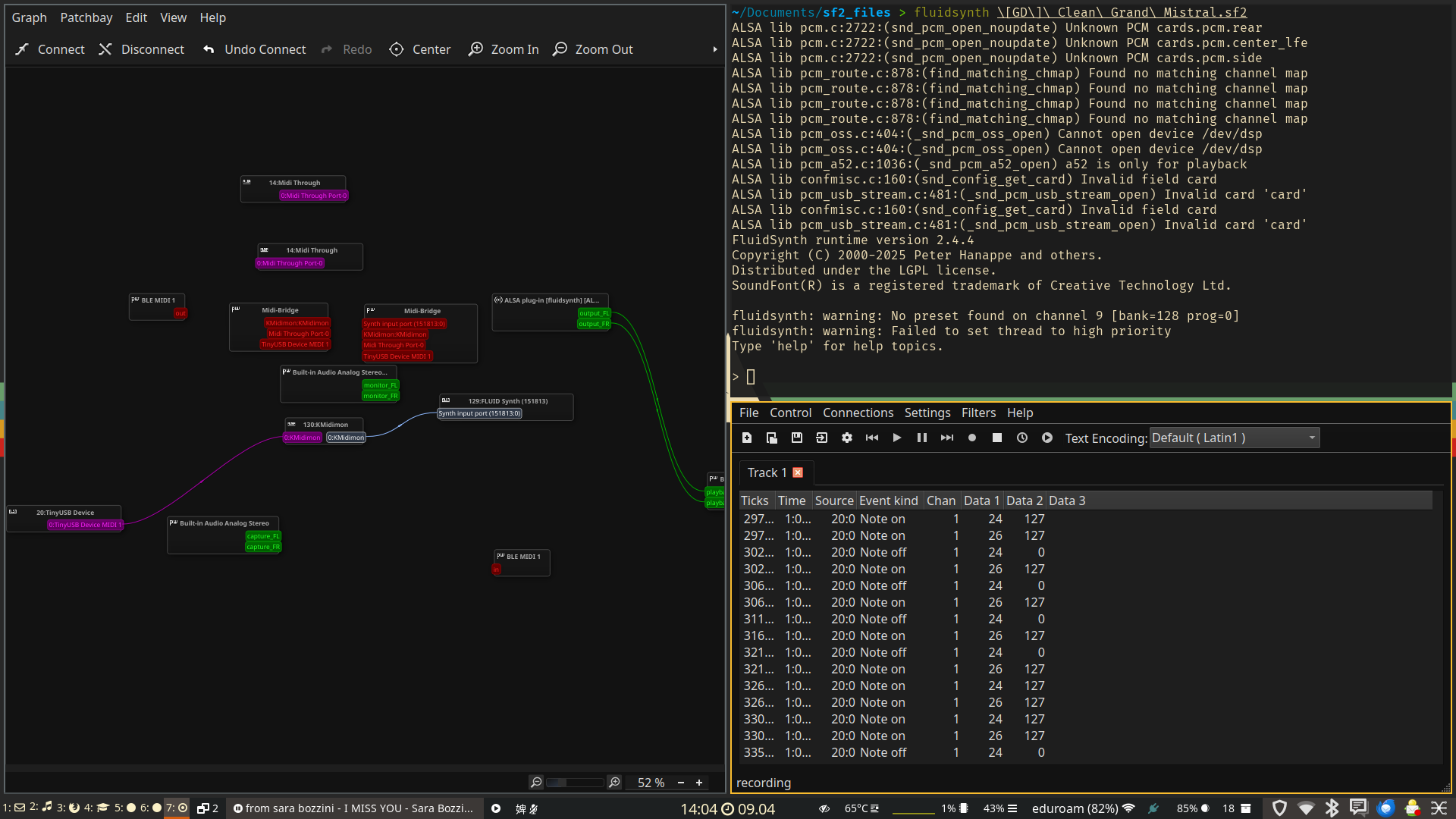
And it worked ok-isch, I need to tweak the code a little to improve the performance.
11.4. Design Files
11.5. Notes
11.5.1. ESP Now
11.5.1.1. Example code
uses flash memory for wifi, but I didn’t wont to go deeper in it