
Final Project Weekly Assignments
W1 | Proposal
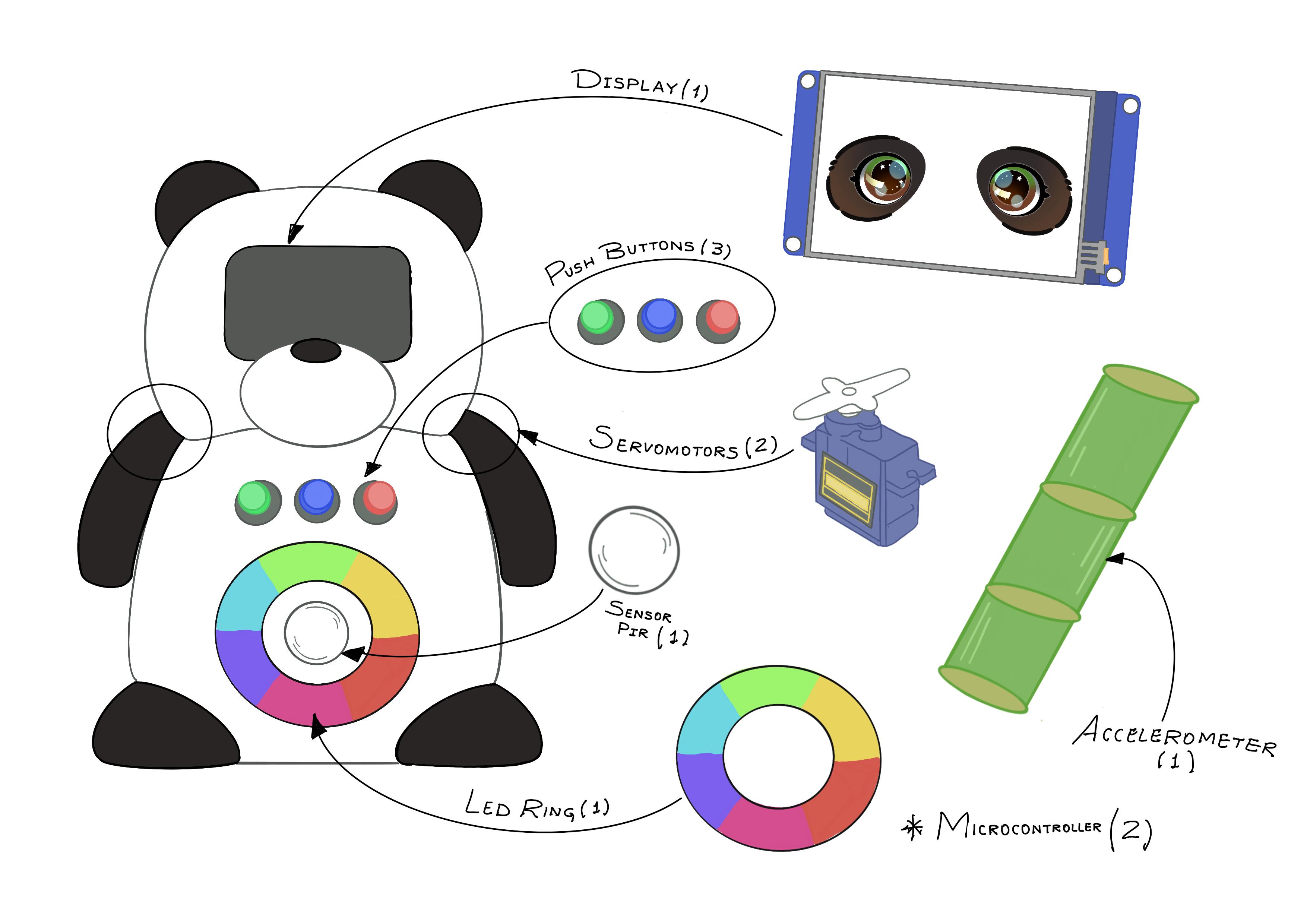
Where it all began
This week the task was to plan and sketch a potential final project. After researching and reflecting, the concept took shape: a panda-shaped robot that helps children learn to recognize and manage their emotions through simple and playful interactions. The first sketch was done. 🐼
W2 | Computer-Aided Design
2D Design
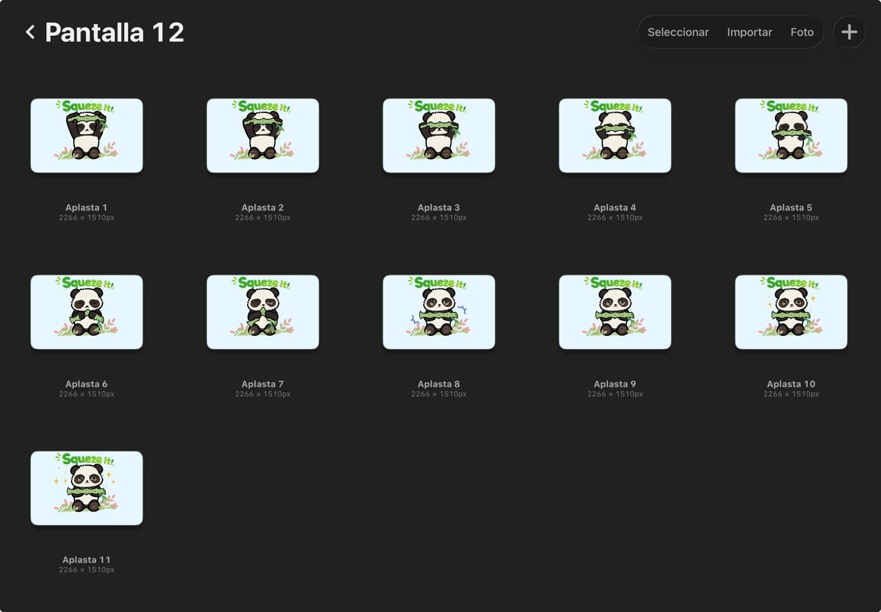
For the 2D design, Procreate was used — an illustration app for iPad that allows drawing directly with the Apple Pencil. Before starting the illustrations, the interaction sequences were defined for each emotional state, drawing from emotional regulation techniques used in child psychology:

Happy
Based on positive reinforcement and emotional validation, the robot celebrates with the child, helping them recognize and embrace positive emotions as something worth expressing.
Sad
The sequence begins with a self-hug to calm down naturally. If the child still does not feel better, a humor therapy sequence follows. If neither works, the robot encourages the child to seek adult support.
Angry
The child channels anger through physical movement using the bamboo accessory. Depending on the intensity detected, the robot guides them through breathing, a squeeze technique, or suggests asking an adult for help.
Additional states were also designed: idle, greeting, and farewell. Since the display does not support video, each state was represented as a sequence of illustrated frames — similar to a GIF. A total of 12 animations were created, each consisting of between 3 and 15 frames depending on the complexity of the movement. Each frame was drawn individually in Procreate, adjusting expressions, shapes, and details to create smooth and readable transitions for a child.
3D Design
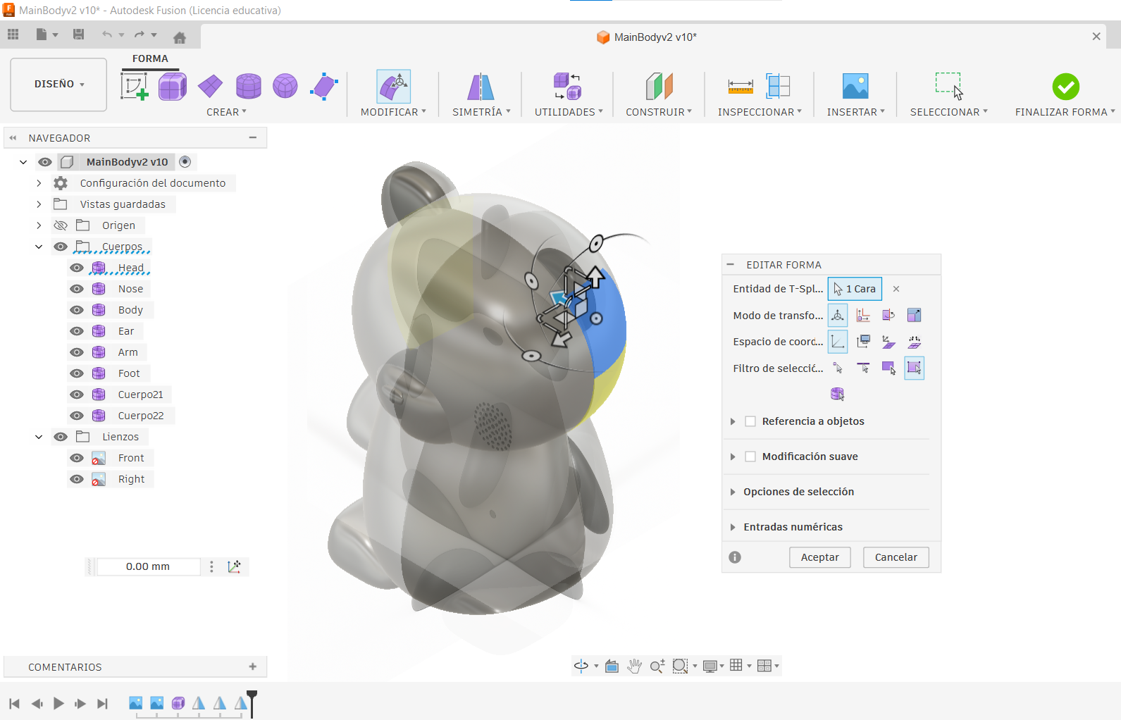
For the 3D design, Autodesk Fusion 360 was used. The process started with reference images generated in ChatGPT, which were imported into Fusion 360 as canvases and used as visual guides throughout the modelling process.
The modelling relied mainly on the Form tool — similar to working with digital clay — to create the organic and rounded shapes of the panda. Once the overall form was defined, Fusion 360's standard modelling tools were used to refine the geometry and prepare each part for fabrication.
Both the robot body and the bamboo accessory were fully modelled with dedicated internal spaces for their respective electronics, including component mounts and cable routing paths. The assembly was designed using a combination of press-fit features, threaded inserts, and screws, providing a secure and clean integration of all parts.
Microcontroller Selection
This week, the XIAO ESP32S3 was selected as the microcontroller for the final project — for both the robot and the bamboo accessory. After comparing different boards and toolchains, the decision was based on its built-in BLE connectivity, compact size, and compatibility with Arduino IDE and C++ — the toolchain I am most familiar with. As a first exploration, a panda illustration was displayed on an OLED screen — an early test of the display logic that would later evolve into the 12 Nextion animations.
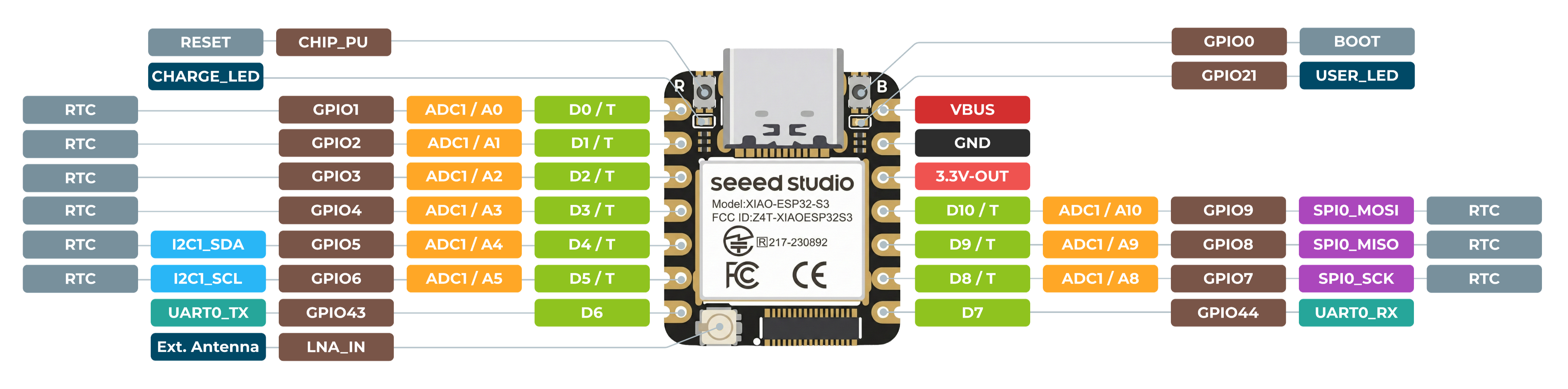
| Board | Component | Pin |
|---|---|---|
| 🐼 Main | Buzzer | D0 |
| 🐼 Main | PIR Sensor | D1 |
| 🐼 Main | Servo 1 | D2 |
| 🐼 Main | Servo 2 | D4 |
| 🐼 Main | LED Ring | D5 |
| 🐼 Main | Display | D6, D7 |
| 🐼 Main | Push Button 1 | D8 |
| 🐼 Main | Push Button 2 | D9 |
| 🐼 Main | Push Button 3 | D10 |
| 🐼 Main | Servomotors, PIR, LED Ring, Display | PWR_5V |
| 🐼 Main | Push Buttons | PWR_3V3 |
| 🌿 Accessory | MPU6050 | D4 (SDA), D5 (SCL) |
| 🌿 Accessory | RGB LED | D7 (R), D8 (G), D9 (B) |
| 🌿 Accessory | MPU6050, RGB LED | PWR_3V3 |
First printed parts
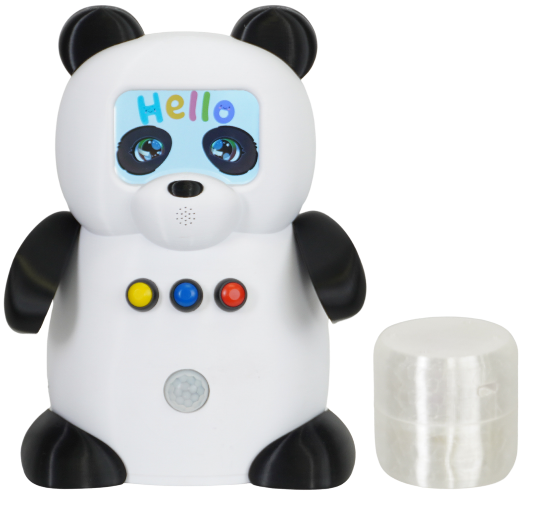
This week, 3D printing was explored as part of the fabrication process for the final project. The Bambu Lab X1 Carbon was used to print the first physical parts of Pambu — testing tolerances, fit, and surface quality. Multicolor printing was applied using black and white filament to match the panda's characteristic appearance. The bamboo accessory was also in early print tests at this stage — a bamboo-shaped piece designed for children to physically interact with by shaking or squeezing it. Its design combines two materials: a transparent PETG inner capsule that allows the RGB LED light to pass through, and a transparent TPU outer layer that gives it a soft, squeezable feel. The infill pattern was being tested and adjusted to find the right balance between structure and softness.
Final Project Board
This week, KiCad was used to design the main PCB for the final project. This was the second version of the board, redesigned as the robot's functionality became clearer. Three push buttons replaced a single test button, each corresponding to an emotional state. A PIR sensor was added for presence detection, the LED Ring replaced a single indicator LED, and a buzzer was incorporated for sound feedback. Power trace widths were also updated — 0.8mm for 5V lines to safely support the servomotors and LED ring, and 0.4–0.5mm for 3.3V signal traces.
Both boards, milled and assembled 🧠🎋
This week, both PCBs for the final project were fabricated using the Carvera CNC milling machine. The Brain Board — the main board for the robot — was milled, soldered, and tested with a 16-LED NeoPixel ring, confirming proper fabrication and correct communication with the XIAO ESP32S3. The accessory board, designed for the bamboo piece, was also fabricated and tested. Both worked on the first try. 🥳
Reading the bamboo 🎋
This week, the MPU6050 accelerometer was interfaced with the accessory board to detect the intensity of movement when a child shakes or squeezes the bamboo piece. The sensor measures acceleration and classifies it into three levels: green at rest, blue on light movement, and red on strong shaking. Hysteresis was applied to prevent flickering between states. This test confirmed that the sensor can reliably distinguish the three intensity levels needed to trigger the robot's different responses.
Panda's face comes alive 🐼
This week, the Nextion NX4832T035 display was connected to the final project board and programmed to show the robot's first animation — a blinking eye sequence used as proof of concept. The display handles the animation internally using a timer, while the XIAO ESP32S3 communicates with it via UART to control which screen to show at each moment. This is the main way Pambu communicates visually with the child during each interaction.
Bamboo talks to Panda 🎋📡🐼
This week, BLE (Bluetooth Low Energy) communication was established between the two custom boards of the project. The accessory board acts as the BLE server — it reads acceleration data from the MPU6050 and broadcasts it wirelessly. The main board acts as the client — it receives that data and changes the NeoPixel LED ring color according to the movement intensity detected. This is the wireless link that connects the bamboo accessory to the robot during the angry state interaction.
Everything comes together 🐼
This week, all the components of the robot were integrated into the final physical assembly. The body was fully printed and assembled, with each component in its dedicated space — servomotors in the torso, PIR sensor at the front, NeoPixel ring behind the belly wall, display mounted flush in the face, and the main board in the base. Cable routing channels were added after the first prototype revealed disorganized wiring. The connection system was also redesigned — magnets were replaced with threaded inserts and screws after the first version proved too heavy. The bamboo accessory was still in PETG and TPU print tests at this stage.
Pambu, fully functional 🐼✨
This week marked the completion of the project. All three emotional sequences execute correctly — each button triggers the right combination of display animation, LED ring, servomotors, and buzzer. BLE communication between the robot and the bamboo accessory is stable, correctly classifying low, medium, and high movement intensity. The system returns to idle after every interaction. Seeing the project as a whole — from the first sketch to a working robot — made this one of the most rewarding moments of the program.
🛠️ Build Guide
1. Design Files
10 pieces, two materials
The robot body is made of 8 pieces — front, back, two arms, two feet, the tail, and the base where the Main Board is housed — printed in black and white PLA to match the panda's appearance. The bamboo accessory adds 2 more pieces: a transparent PETG inner capsule and a transparent TPU outer shell, designed to be soft and squeezable while letting the RGB LED light through.
Frame-by-frame animations (Procreate)
The animation process started in Procreate, where each expression was drawn frame by frame. In total, 12 animations were created for the robot's emotional states (happiness, sadness, and anger), as well as its idle, greeting, and farewell sequences. Depending on the amount of movement, each animation contained between 3 and 15 frames. Once finished, all frames were resized to 480 × 320 px to match the Nextion NX4832T035 display and imported into Nextion Editor. Since the display does not support native video playback, the frames were displayed sequentially using a timer to create the animation effect.
The 2D/3D design process is documented in Week 2 — Computer-Aided Design.
2. Electronics
Main Board + Accessory Board
The robot runs on two custom PCBs. The Main Board is the central board, hosting the XIAO ESP32S3, three push buttons, PIR sensor, NeoPixel LED ring, buzzer, two servomotors, and the display. The Accessory Board lives inside the bamboo piece, hosting the MPU6050 accelerometer and an RGB LED, and communicates wirelessly with the Main board via BLE. Both boards were designed in Week 6, fabricated and soldered in Week 8, where the full soldering process for both boards is documented.
| Board | Component | Pin |
|---|---|---|
| 🐼 Main | Buzzer | D0 |
| 🐼 Main | PIR Sensor | D1 |
| 🐼 Main | Servo 1 | D2 |
| 🐼 Main | Servo 2 | D4 |
| 🐼 Main | LED Ring | D5 |
| 🐼 Main | Display | D6, D7 |
| 🐼 Main | Push Button 1 | D8 |
| 🐼 Main | Push Button 2 | D9 |
| 🐼 Main | Push Button 3 | D10 |
| 🐼 Main | Servomotors, PIR, LED Ring, Display | PWR_5V |
| 🐼 Main | Push Buttons | PWR_3V3 |
| 🎋 Accessory | MPU6050 | D4 (SDA), D5 (SCL) |
| 🎋 Accessory | RGB LED | D7 (R), D8 (G), D9 (B) |
| 🎋 Accessory | MPU6050, RGB LED | PWR_3V3 |
The full Bill of Materials (BOM) with part numbers, quantities, and sourcing is documented in Week 18.
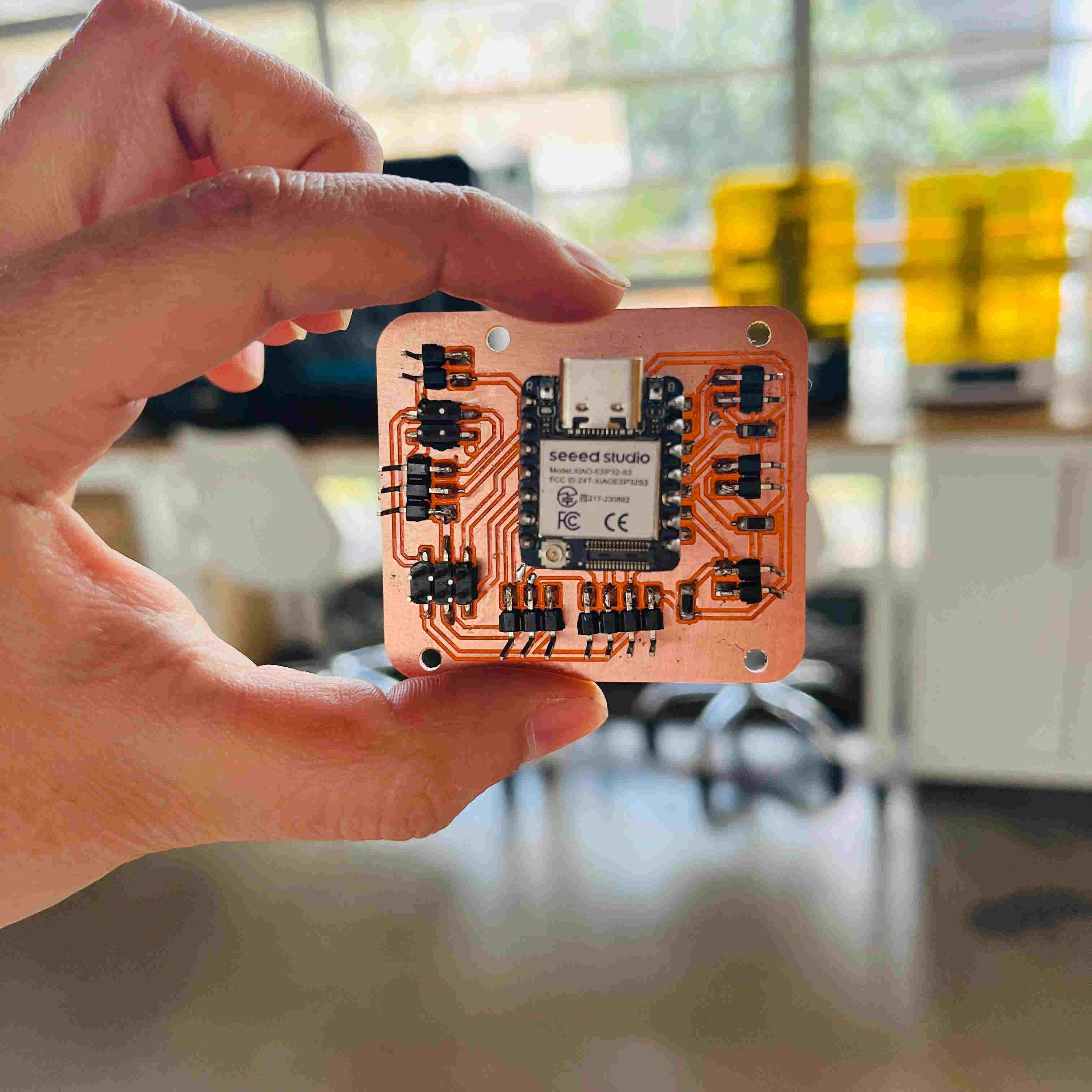
Main Board — fully soldered
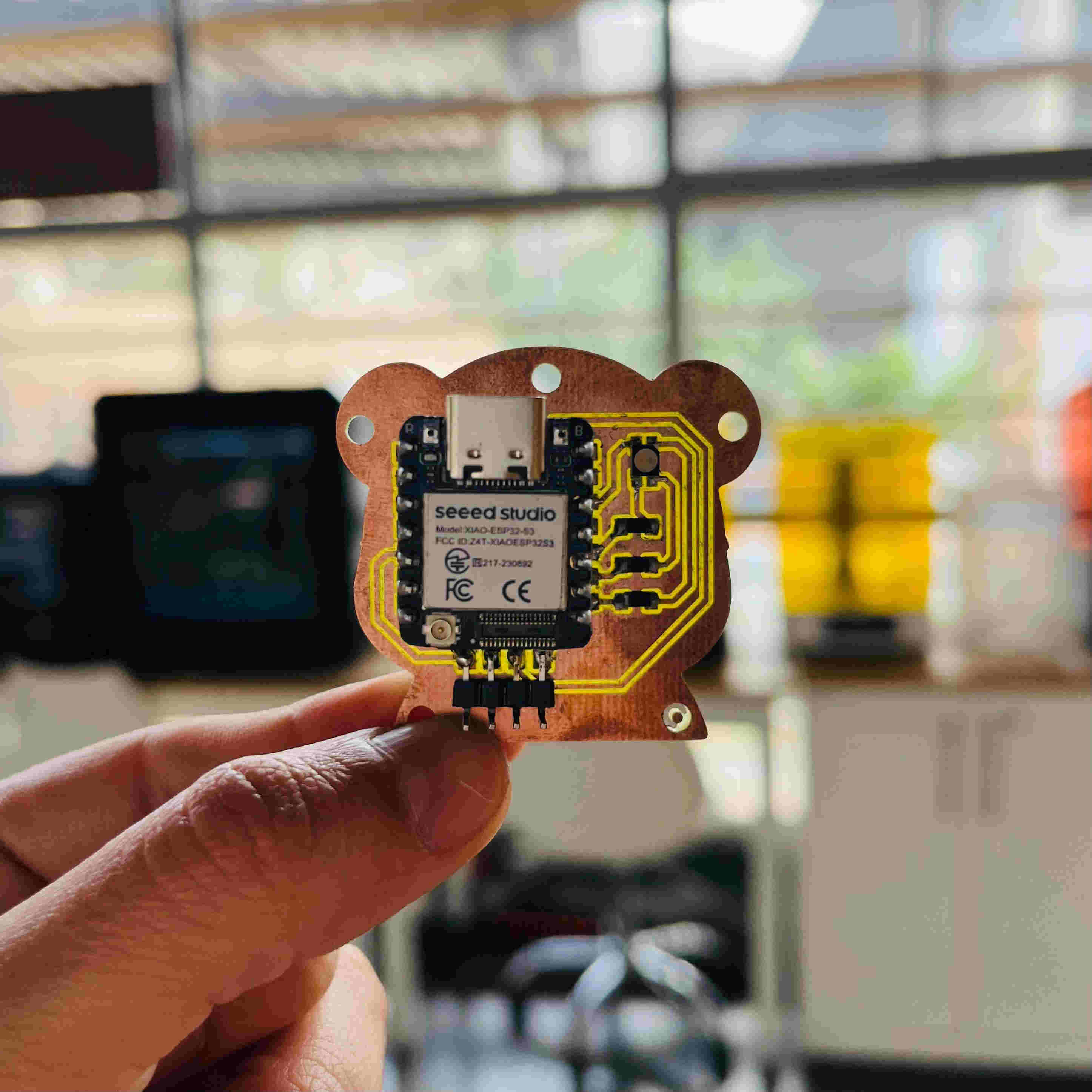
Accessory Board — fully soldered
3. Power Management
Main Board
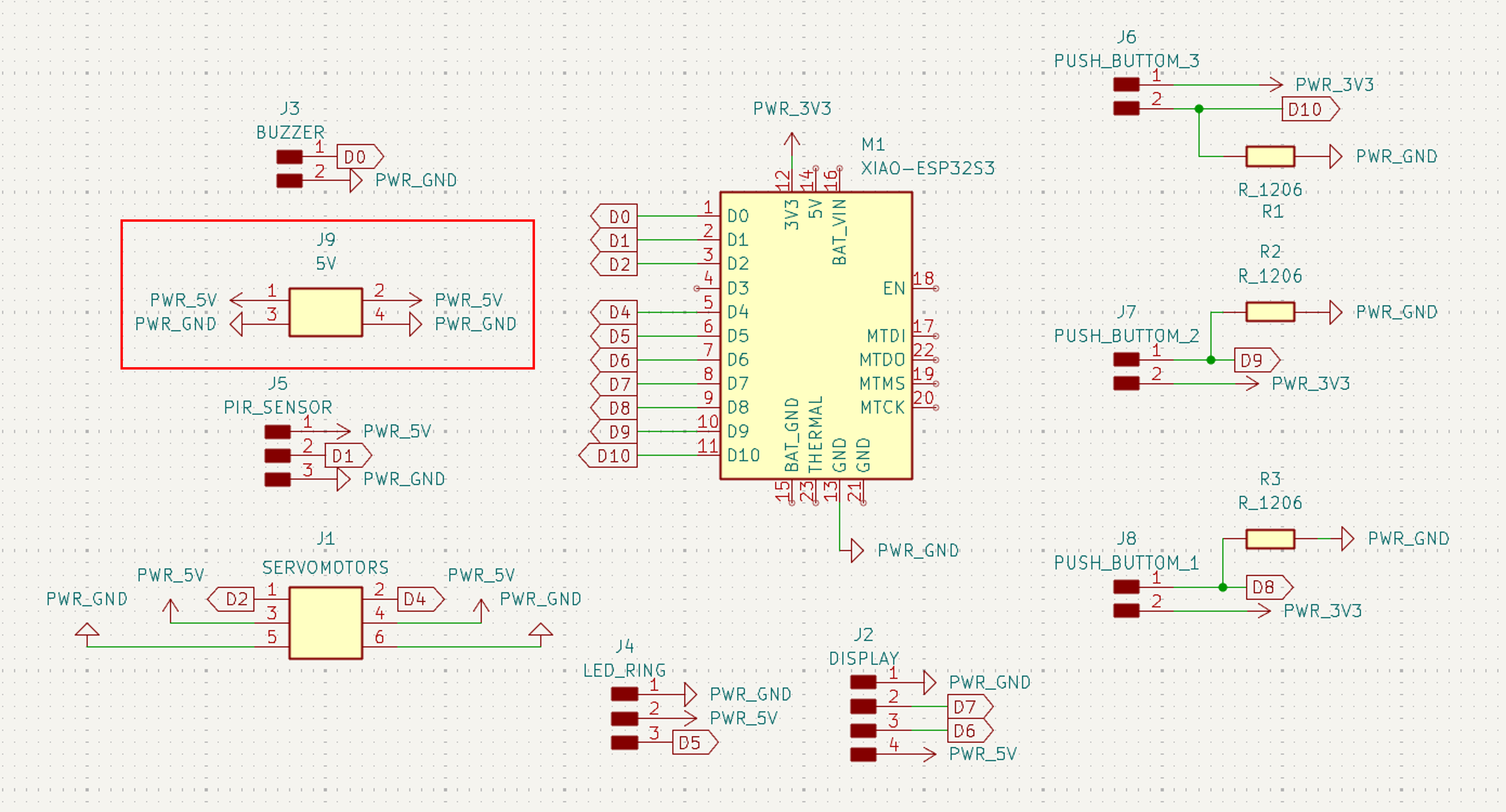
The Main Board was designed to be powered by a 5V charger, connected through the J9 connector highlighted in red on the schematic. J9 has two ports — one pair of 5V/GND pins connects to the charger's cable, and the second pair connects internally to the XIAO ESP32S3 to power the board. No external regulator circuit is needed outside the board. From there, the board distributes power internally: components that need 5V (servomotors, PIR sensor, LED ring, display) are wired to the PWR_5V rail, while the push buttons run on the PWR_3V3 rail, supplied by the XIAO ESP32S3's onboard regulator.
💡 Note — XIAO mounting
The XIAO ESP32S3 modules were not soldered directly onto the PCBs. Instead, pin headers were soldered to each XIAO, while the corresponding PCBs were assembled with matching female pin sockets. This configuration allows the microcontrollers to be installed and removed without desoldering, facilitating programming, testing, and replacement when needed.
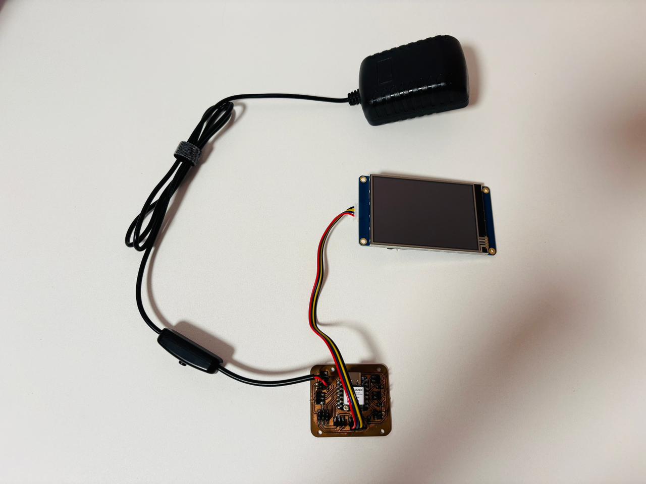
5V charger plugged into the Main Board, with display attached
💡 Note — Main Board power adapter
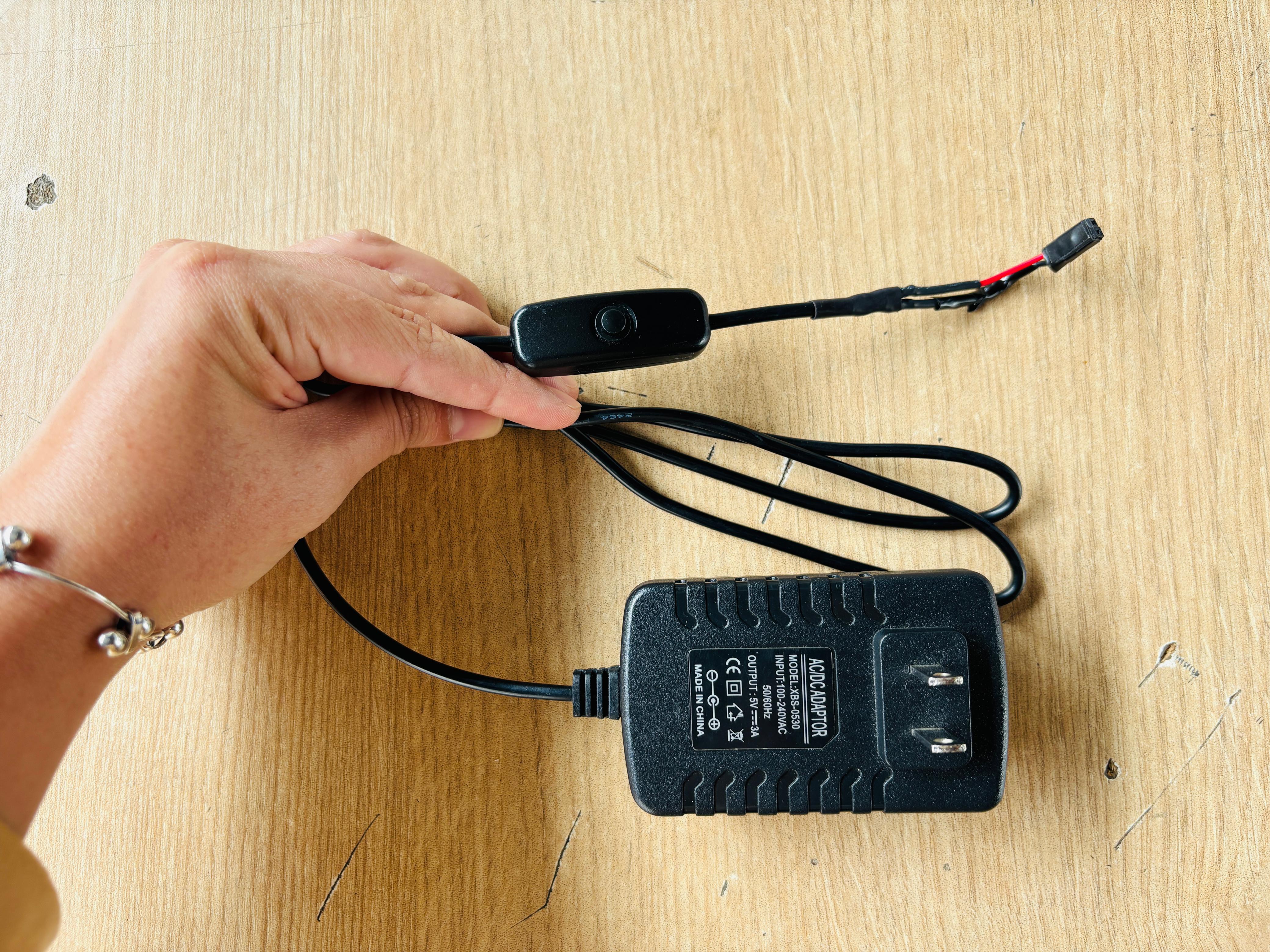
The Main Board is powered by a generic AC/DC adapter (model XBS-0530), rated for 100–240VAC input and a 5V / 3A output — well within the requirements of the servomotors, LED ring, display, and other onboard components. The inline switch on the cable, which came with the charger, is used to turn the robot on and off without unplugging it, and the cable ends in a connector that plugs directly into the Main Board's J9 power port.
Accessory Board
The Accessory Board, inside the bamboo piece, runs independently — powered by a LiPo battery soldered directly to the XIAO ESP32S3's battery pads, supplying 3.3V to the MPU6050 and RGB LED. Since it communicates wirelessly via BLE, no cable connects it to the Main Board.
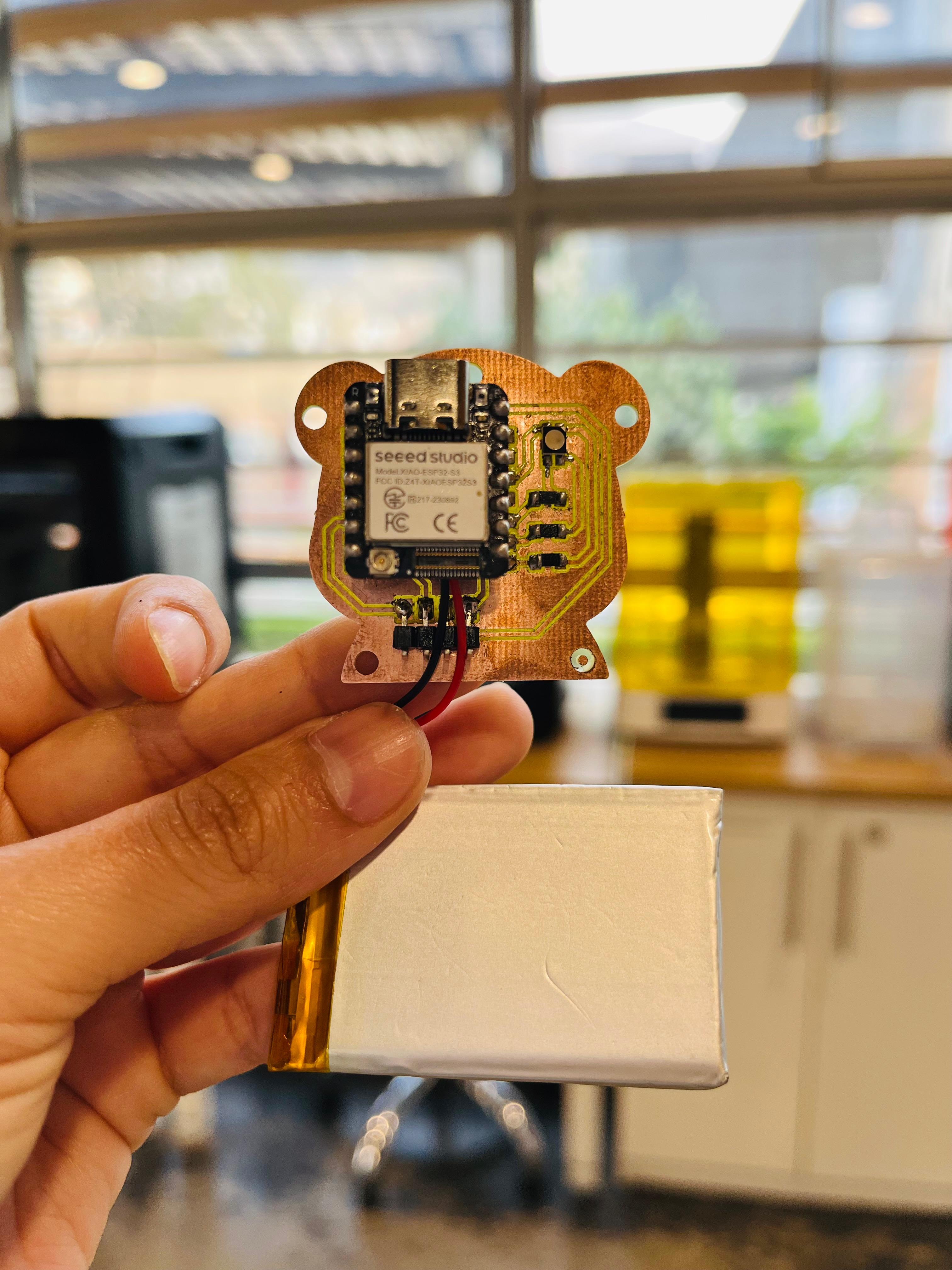
LiPo battery soldered directly to the Accessory Board's XIAO ESP32S3
💡 Note — Accessory Board battery
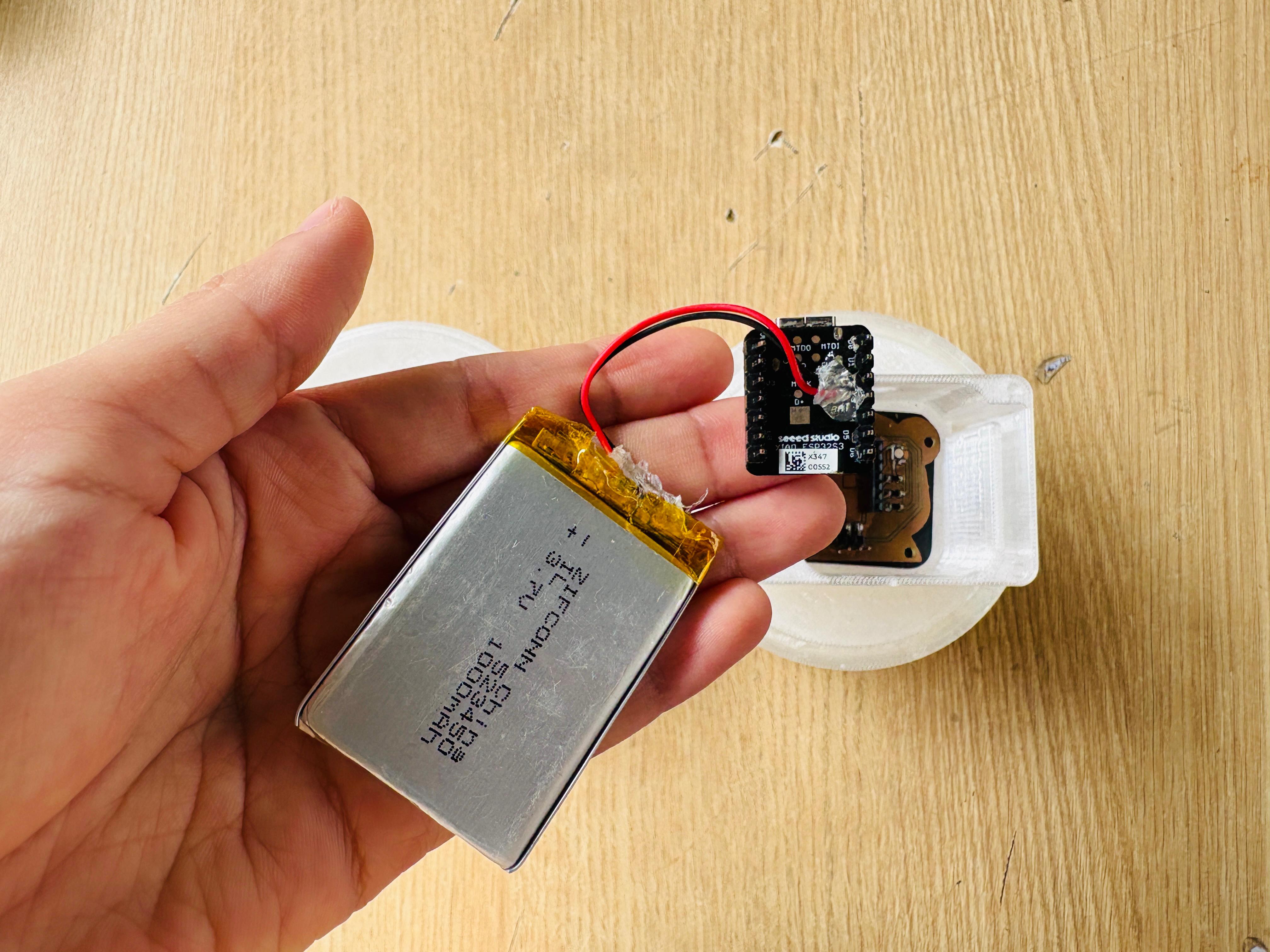
The XIAO ESP32S3 includes a built-in power management chip, I was able to connect the battery directly to its BAT+ and BAT- pads without adding an external charging circuit. Before soldering, I checked Seeed Studio's official documentation to verify the battery terminal polarity, confirming that the negative terminal should be placed closest to the USB port and the positive terminal on the opposite side. After soldering a 3.7 V rechargeable LiPo battery to the pads, I applied silicone over the connections to insulate the solder joints and provide additional mechanical support, ensuring that the wires remained firmly in place during handling.
4. Integration
Robot (main body)
Integration was carried out progressively throughout the build process. After the parts were fabricated and printed, each electronic component was installed into its designated location as the assembly advanced, including the Main Board, servomotors, PIR sensor, LED ring, buzzer, and display. Once all components were in place, the structure was secured using threaded inserts and screws. With the hardware fully assembled, software integration followed. The Nextion display animations were developed first, after which the Main Board firmware was implemented to coordinate the buttons, sensors, servomotors, LED ring, and buzzer, ensuring that each interaction produces the corresponding animation, lighting, movement, and sound.
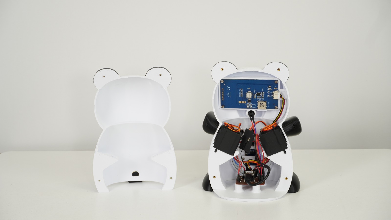
| Step | What was done |
|---|---|
| 1 | 🖨️ Print the body parts — front, back, two arms, two feet, the tail, and the base. |
| 2 | 🔌 Install electronics as parts were printed — Main Board, servomotors, PIR sensor, LED ring, buzzer, and display mounted in their dedicated spaces. |
| 3 | 🔩 Secure the structure — all pieces joined using threaded inserts and screws. |
| 4 | 🖥️ Program the display — Nextion animations programmed first, once physically assembled. |
| 5 | ⚙️ Program the electronics — buttons, sensors, servomotors, LED ring, and buzzer logic, linked to the display so each button triggers the matching animation and physical response. |
Bamboo accessory
Integration of the bamboo accessory followed a simpler workflow, as it operates independently from the robot. The PETG inner capsule and TPU outer shell were assembled around the Accessory Board, MPU6050, RGB LED, and a LiPo battery soldered directly to the XIAO ESP32S3. Once the assembly was complete, the accessory was programmed with its dedicated firmware, which reads acceleration data from the MPU6050 and transmits it wirelessly to the Main Board via BLE.
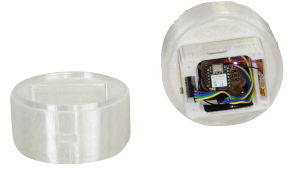
| Step | What was done |
|---|---|
| 1 | 🖨️ Print the two pieces — PETG inner capsule and TPU outer shell. |
| 2 | 🔋 Install the Accessory Board, MPU6050, RGB LED, and LiPo battery soldered to the XIAO ESP32S3, then close the piece. |
| 3 | 📡 Program the accessory — independent code handling the MPU6050 readings and BLE communication with the main robot. |
Every iteration of Pambu, side by side. 🐼
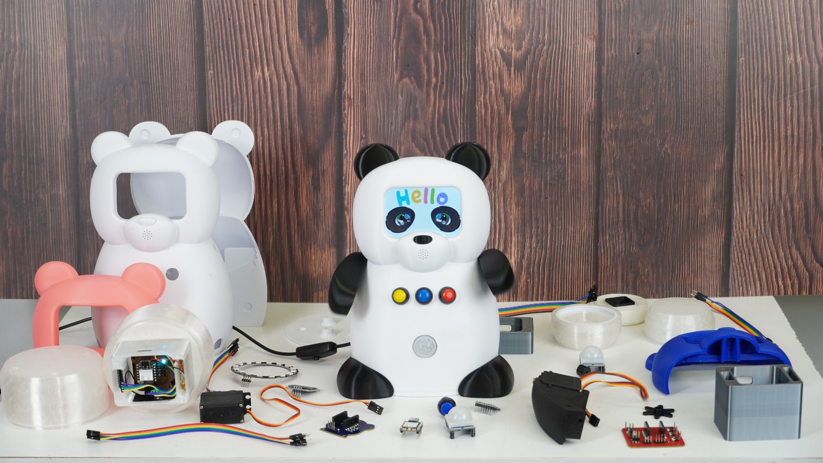
The evolution of Pambu, across every iteration
💭 Final Thought
Looking back, Pambu went far beyond what I imagined when I first sketched it during the first cycle. At that stage, it was simply an initial idea—a robot concept designed to provide emotional support. Seeing it now as a fully functional robot, complete with its own electronics, animations, and its own accessory, surprised me more than I ever expected.
The second cycle gave me the opportunity to implement the improvements I had planned from the first round but had not been able to fully develop at the time. I was able to accomplish most of them, making this cycle feel like genuine progress. There is still plenty of room to grow, and I hope that by continuing to learn, experiment, and explore AI, I can eventually give Pambu the ability to better recognize emotions and respond in a more natural and supportive way.
What I take away from this experience is equally technical and personal. On the technical side, I learned a great deal about designing and integrating mechanical, electronic, and software subsystems into a single product. I also learned that patience is an essential engineering skill because things rarely work perfectly on the first attempt. Writing the documentation taught me another lesson: my attention to detail often made the process longer than expected, but over time I became much more efficient and confident in knowing when a section was ready to move forward.
Although I am an Industrial Engineer and my professional path has mainly focused on other areas, electronics, mechanics, and programming have always fascinated me. That interest began with a technology course in high school, where I discovered how rewarding it was to build things from scratch. Even though I chose a different direction at university, I never lost that curiosity. Joining the Fab Lab at ESAN allowed me to reconnect with that passion and reminded me how much I enjoy creating, experimenting, and learning through hands-on projects.
On the personal side, this project is deeply connected to people who matter to me. It was inspired by my internship, where I met many children who require emotional support, as well as by my cousin's story and my family's experiences. Together, these experiences showed me how meaningful even small forms of emotional support can be. Because of that, finishing Pambu feels like much more than completing an academic project. It is proof that an idea born from empathy, personal experiences, and curiosity can become something real that has the potential to make a positive difference.