W4 | Embedded Programming
📝 Group Assignment:
- Demonstrate and compare the toolchains and development workflows for available embedded architectures.
- Document your work to the group work page and reflect on your individual page what you learned.
What We Did
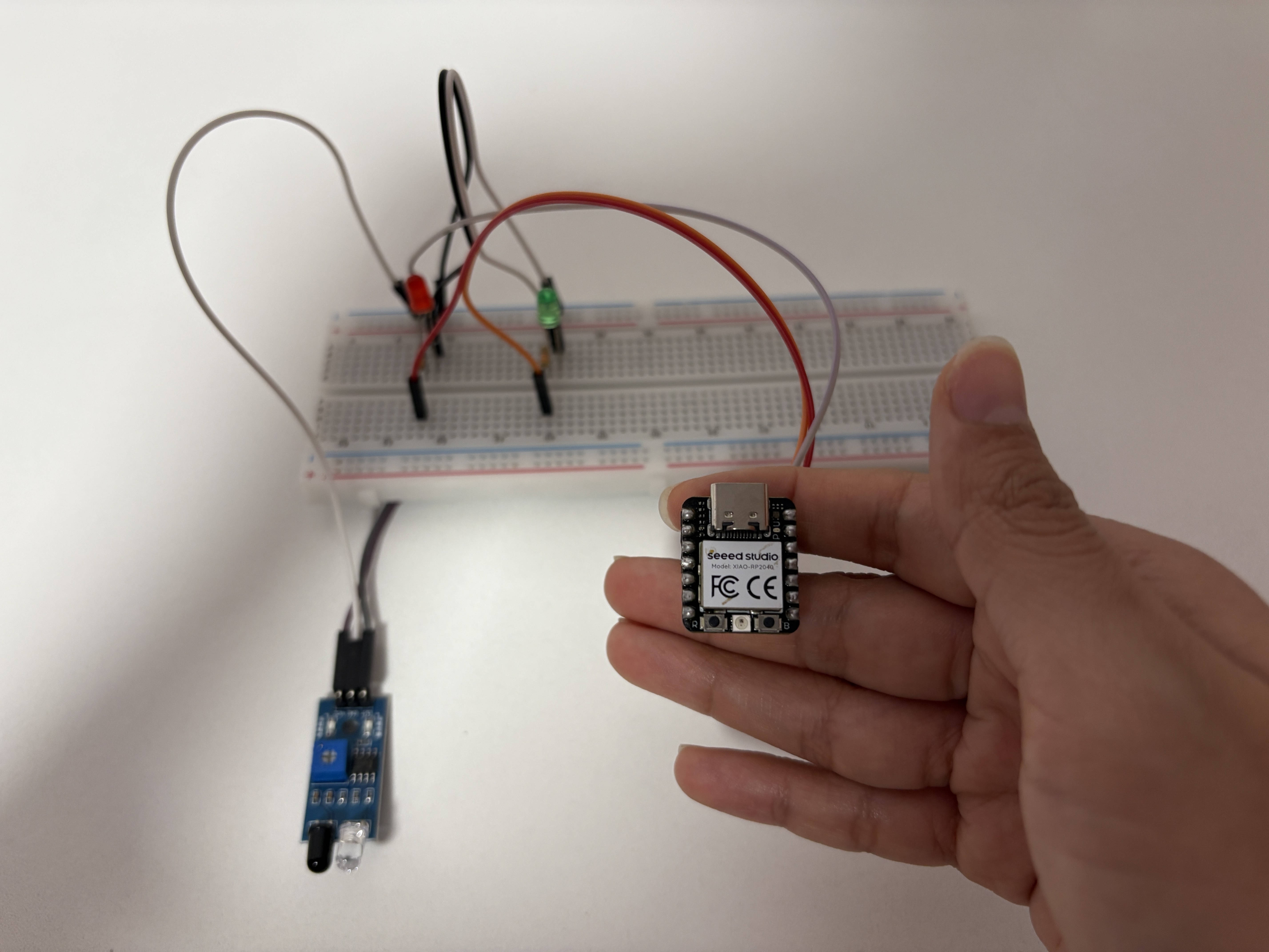
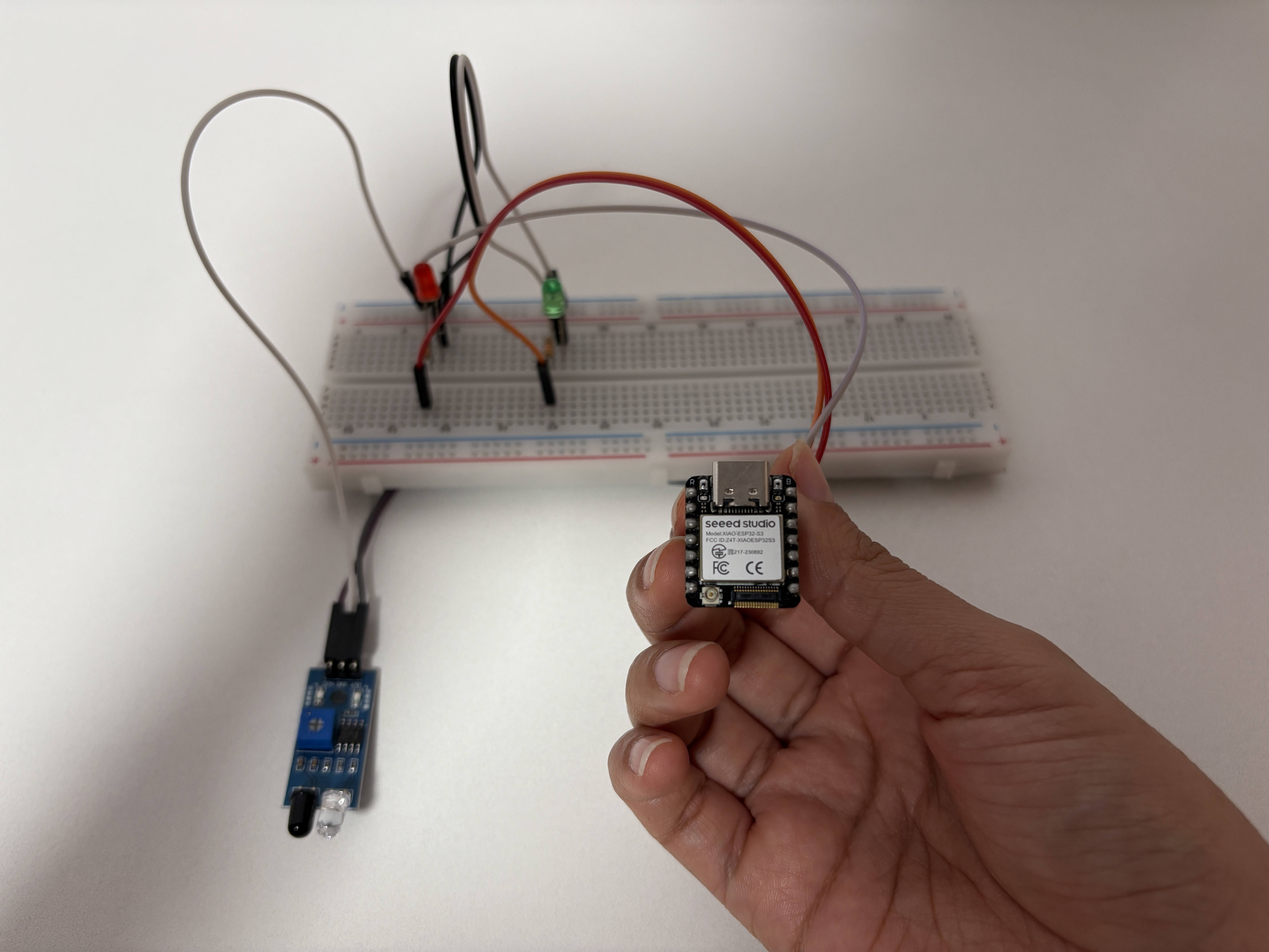
For this group assignment, we programmed two different microcontroller families using different toolchains and compared the development workflow from setup to execution. The boards we used were the XIAO RP2040 and the XIAO ESP32-S3 Sense, both from Seeed Studio but based on different architectures. We implemented the same project on both boards: an IR obstacle detector with two LEDs and serial communication. This allowed us to focus on how each toolchain and workflow behaves under similar conditions.
The Boards
| XIAO RP2040 | XIAO ESP32-S3 Sense | |
|---|---|---|
| Chip | RP2040 | ESP32-S3 |
| Architecture | ARM Cortex-M0+ | Xtensa LX7 |
| Speed | 133 MHz | 240 MHz |
| RAM | 264 KB | 512 KB + 8MB PSRAM |
| WiFi/BT | ❌ | ✅ |
| IDE | Arduino IDE | Thonny |
| Language | C++ | MicroPython |
Both boards look almost identical from the outside — same size, same pin layout — which made us think they would work similarly. But once we started setting them up, it became clear they are very different worlds.

Something important to mention is that the ESP32-S3 can also be programmed using Arduino IDE with C++, just like the RP2040. But for this assignment we decided to use a different toolchain on each board on purpose — Arduino IDE with C++ for the RP2040, and Thonny with MicroPython for the ESP32-S3.
💻 XIAO RP2040 — Arduino IDE + C++
The Circuit
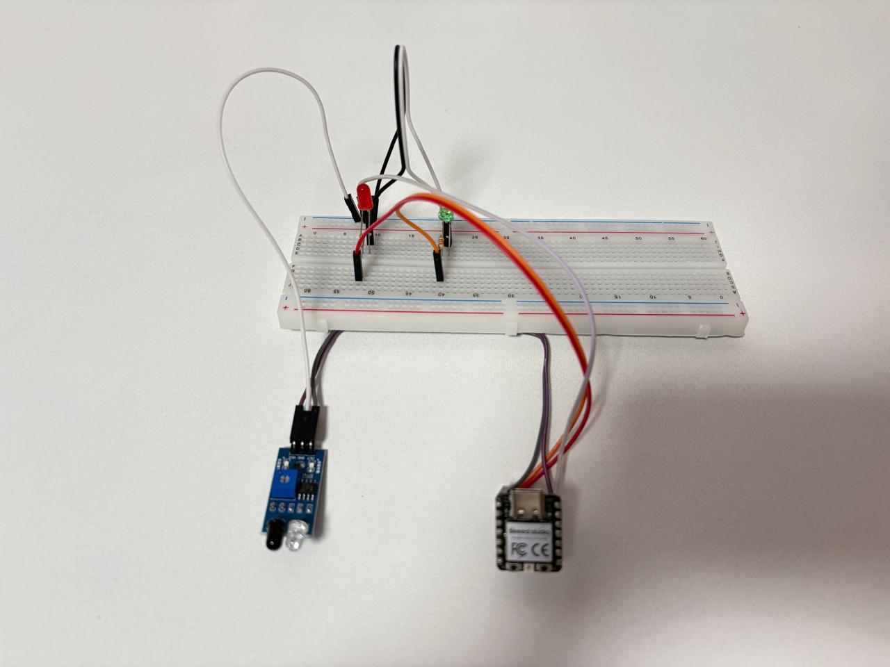
We assembled the circuit on a breadboard connecting an IR obstacle sensor, a red LED, and a green LED to the XIAO RP2040. Each LED was connected through a 330Ω resistor to protect it from excess current. The IR sensor has three pins — VCC and GND for power, and an OUT pin that sends the signal to the board. The red LED indicates when an obstacle is detected, and the green LED lights up when the path is clear.
Toolchain Setup
Arduino IDE was already installed. To add support for the RP2040 we went to 🌐 File > Preferences and added the following URL to the board manager. Then in 🌐 Tools > Board > Boards Manager we searched for "RP2040" and installed the package by Earle F. Philhower III. Finally we selected 🖰 Seeed XIAO RP2040 from the board list.
https://github.com/earlephilhower/arduino-pico/releases/download/global/package_rp2040_index.json
Workflow
-
Connecting the board
The first time we connected the XIAO RP2040, the upload failed because the board needed to be put into bootloader mode manually. To do this we held the🖰 BOOTbutton, pressed🖰 RESET, and then released BOOT. The board appeared as a USB drive called📁 RPI-RP2in Windows Explorer — which was unexpected at first, since it looks like a regular flash drive. -
Writing and uploading the code
We wrote the program in C++ directly in Arduino IDE. Once the code was ready, we clicked🖰 Uploadand Arduino IDE compiled the code, converted it to UF2 format, and deployed it to the board automatically. The whole process took a few seconds. -
Testing and debugging
We opened🌐 Tools > Serial Monitorat🖰 9600 baudand saw the messages from the board in real time. Every time the IR sensor changed state, a message appeared instantly. This made it very easy to verify the code was working correctly without any extra tools.
💻 XIAO ESP32-S3 Sense — Thonny + MicroPython
The Circuit
For the ESP32-S3 we used the exact same components — IR sensor, red LED, green LED, and 330Ω resistors. Since both boards share the XIAO pin layout, we simply moved the components from one board to the other on the breadboard without changing any connections.
Toolchain Setup
Unlike the RP2040, the ESP32-S3 required more preparation before writing any code. MicroPython is not pre-installed, so we had to set up the environment first.
-
We started by installing Python 3.14 on Windows. Then we installed esptool via the command line:
py -m pip install esptool -
We downloaded the MicroPython firmware (.bin file) from:
https://micropython.org/download/ESP32_GENERIC_S3/ -
To put the ESP32-S3 in bootloader mode we held
🖰 BOOTwhile connecting the USB cable. Then we erased the flash memory:py -m esptool --chip esp32s3 --port COM12 erase_flash -
And flashed the MicroPython firmware:
py -m esptool --chip esp32s3 --port COM12 write_flash -z 0x0 ESP32_GENERIC_S3-20260406-v1.28.0.bin
Workflow
-
Connecting Thonny
We opened Thonny and went to🌐 Run > Configure interpreter, selected🖰 MicroPython (ESP32)and the port📁 Board CDC @ COM13. The shell immediately showed: -
Writing and uploading the code
We wrote the program in MicroPython directly in Thonny. One big difference from Arduino IDE is that Thonny has an interactive shell (REPL) — we could test individual lines of code instantly before writing the full program, which made the development process much more exploratory. -
Testing and debugging
We ran the script with🖰 F5and saw the output directly in Thonny's shell. To make the program run automatically on every boot, we saved it as📁 main.pydirectly on the device using🌐 File > Save as > MicroPython device.
MicroPython v1.28.0 on 2026-04-06;
Generic ESP32S3 module with ESP32S3
>>>
Comparing the Toolchains & Workflows
For this assignment, each board was programmed using a different toolchain — a different combination of software, language, and workflow.
1. Setup
With Toolchain A, setup was straightforward — install the board package in Arduino IDE and start coding. With Toolchain B, the process required more steps: install Python and esptool, download the MicroPython firmware, and flash it to the board through the terminal. More involved, but it gave a clearer understanding of how a board is prepared to run code.
2. Uploading Code
In Arduino IDE, the code is compiled before being sent to the board — errors are caught before anything is uploaded. In Thonny, there is no compilation step — MicroPython runs directly on the board line by line as soon as the script is executed.
3. Debugging
Thonny's interactive shell allows testing individual commands instantly, without uploading a full program. This makes it easy to verify that a component works before writing the full code. In Arduino IDE, every change requires compiling and uploading again before seeing the result.
4. Code Structure
C++ requires explicit structure and syntax — variable types, setup(), loop(). MicroPython is shorter and more flexible.
| Toolchain A — RP2040 + Arduino + C++ | Toolchain B — ESP32-S3 + Thonny + MicroPython | |
|---|---|---|
| Setup | Install board package → start coding | Install Python + esptool → flash firmware |
| Upload method | Compile → deploy automatically | Run script directly in Thonny |
| Development style | Write → Compile → Upload → Test | Write → Run instantly in shell |
| Error feedback | Before upload (compile time) | While running (runtime) |
| Code style | Verbose, structured | Concise, readable |
| Stood out for | Fast compile, familiar workflow | Interactive shell, quick iteration |
🧠 What I Learned
This assignment showed me that the toolchain affects how I work with the hardware.
Even though both boards achieved the same result, the process was different. The setup, the way code is uploaded, and how errors are handled all changed depending on the toolchain.
Working with both helped me see that there is not a single way to program a board. Each workflow has its own advantages depending on what you need.
It also helped me understand a bit more what happens behind the process, especially during setup and uploading.
This will help me choose the most suitable toolchain for developing my final project.
📝 Individual Assignment:
- Browse through the data sheet for your microcontroller.
- Write a program for a microcontroller, and simulate its operation, to interact (with local input &/or output devices) and communicate (with remote wired or wireless connection).
Looking for a Microcontroller
After going through the group assignment, I chose to work with the XIAO ESP32-S3 Sense for my final project. I am more familiar with programming in Arduino IDE using C++, which made it easier for me to develop and test my code. My project also requires communication between devices, so having built-in WiFi is important. The ESP32-S3 supports wireless communication, which fits this requirement. To better understand how to use it, I reviewed its datasheet and focused on the features relevant to my project.
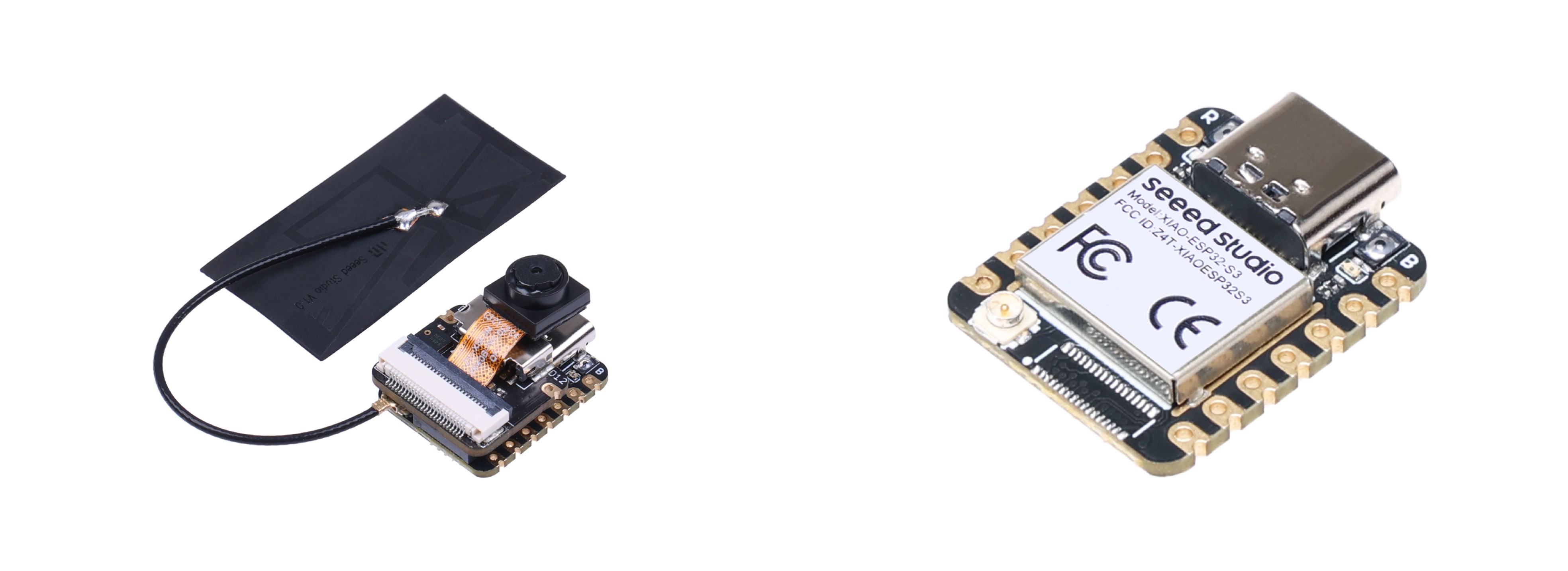
XIAO ESP32S3 Sense
📋 XIAO ESP32-S3 Sense — Reading the Datasheet
Reading a datasheet for the first time can feel intimidating — it is a very long and technical document. But you do not need to understand everything in it. The goal is to know where to find the information you need when you need it. You can access the full datasheet here: ESP32-S3 Technical Reference Manual
These were the sections I found most useful:
Processor
Runs at up to 240 MHz with two cores. In simple terms, this means the board can do two things at the same time — for example, handle WiFi while running your code.
GPIO Matrix
Explains something important: the pins on this board are flexible. Unlike simpler boards where each pin has one fixed function, almost any pin on the ESP32-S3 can be configured to do different things depending on your project.
Communication Protocols — UART, I2C, SPI
These are not just names on a spec sheet. Each one is used for a different type of connection, and knowing the difference helps when connecting sensors or other devices.
Memory
Clarifies the difference between flash (where your program is stored permanently) and RAM (where data lives while the program is running). The ESP32-S3 has 8MB of each, which is a lot for a board this size.
Key Features Summary
| Feature | Value | What it means |
|---|---|---|
| Processor | Xtensa LX7 dual-core, 240 MHz | Can run two tasks simultaneously |
| Flash memory | 8 MB | Stores your program permanently |
| RAM | 8 MB PSRAM | Memory available while running |
| WiFi | 2.4 GHz | Wireless internet connection |
| Bluetooth | BLE 5.0 | Short-range wireless communication |
| Digital pins | D0–D10 | Read sensors, control LEDs |
| Analog pins | A0–A3 | Read values between 0 and 4095 |
| UART | TX, RX | Serial communication with computer |
| I2C | SDA, SCL | Connect multiple devices with 2 wires |
| SPI | MOSI, MISO, SCK | High-speed communication for camera, screens |
| Camera | OV2640, 1600×1200 | Built-in on the Sense version |
| Power input | USB-C 5V | Standard charging cable |
⚡ What Makes This Microcontroller Special
While browsing the datasheet, a few features stood out that make the ESP32-S3 more than just a regular microcontroller. At the beginning, the idea for my final project was to integrate AI functionalities. Although I still have a lot to explore in that area, this microcontroller already provides the capabilities to support it. For now, I am focusing on building the base of the system, but in a future version of the robot, I plan to take advantage of these features.
AI acceleration built into the chip
The ESP32-S3 includes special processor instructions designed to speed up machine learning operations. This means the board can process data locally — for example, recognizing faces or detecting objects through the camera — without needing to send anything to the internet.
Built-in camera support
The datasheet describes a dedicated LCD/Camera controller that manages communication with the OV2640 camera included in the Sense version. This is not an add-on — it is part of the chip architecture, which makes image capture much more efficient than connecting an external camera to a regular microcontroller.
📌 Understanding the Pins
The pinout image shows all available pins on the XIAO ESP32-S3 Sense, color-coded by function. Here are the most important ones to understand:
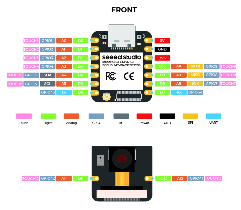
🔴 Power pins — 5V, 3V3, GND
These provide power to the board and connected components. 3V3 and GND are the ones used most often when connecting sensors or LEDs.
🟢 Digital pins — D0 to D12
The most commonly used pins. They can be set as input (read a sensor) or output (control an LED). Each maps to an internal GPIO number — D0 = GPIO1, D1 = GPIO2, and so on.
🟠 Analog pins — A0 to A12
These read a range of values instead of just HIGH or LOW, converted to a number between 0 and 4095. Useful for sensors that output variable signals.
⬛ IIC pins — SDA, SCL
Used for I2C communication — a protocol that connects multiple devices with just 2 wires. Common for sensors and small displays.
🔵 UART pins — TX, RX
The protocol behind serial communication. Every message printed in the Serial Monitor travels through these pins.
Something worth noting is that most pins are multifunctional — the same pin can act as digital, analog, or touch depending on how it is configured in code. This flexibility is one of the things that makes the ESP32-S3 stand out from simpler microcontrollers.
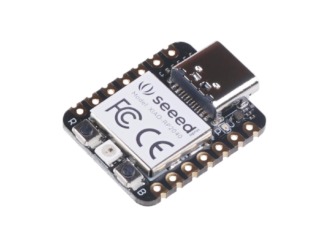
Writing and Testing a Program — XIAO RP2040 with Arduino IDE
For this first test, I worked with the Seeed Studio XIAO RP2040 and programmed it using Arduino IDE. Before jumping into the code, I configured the software environment by following these steps:
- I downloaded and installed the latest version of Arduino IDE according to my operating system.
- I launched the Arduino application.
-
I added the Seeed Studio XIAO RP2040 board package to Arduino IDE:
-
I navigated to
🌐 File > Preferencesand added the following URL to the Additional Boards Manager URLs field:https://github.com/earlephilhower/arduino-pico/releases/download/global/package_rp2040_index.json

-
I went to
🌐 Tools > Board > Boards Manager, searched for "RP2040", selected the latest version of "Raspberry Pi Pico/RP2040", and installed it.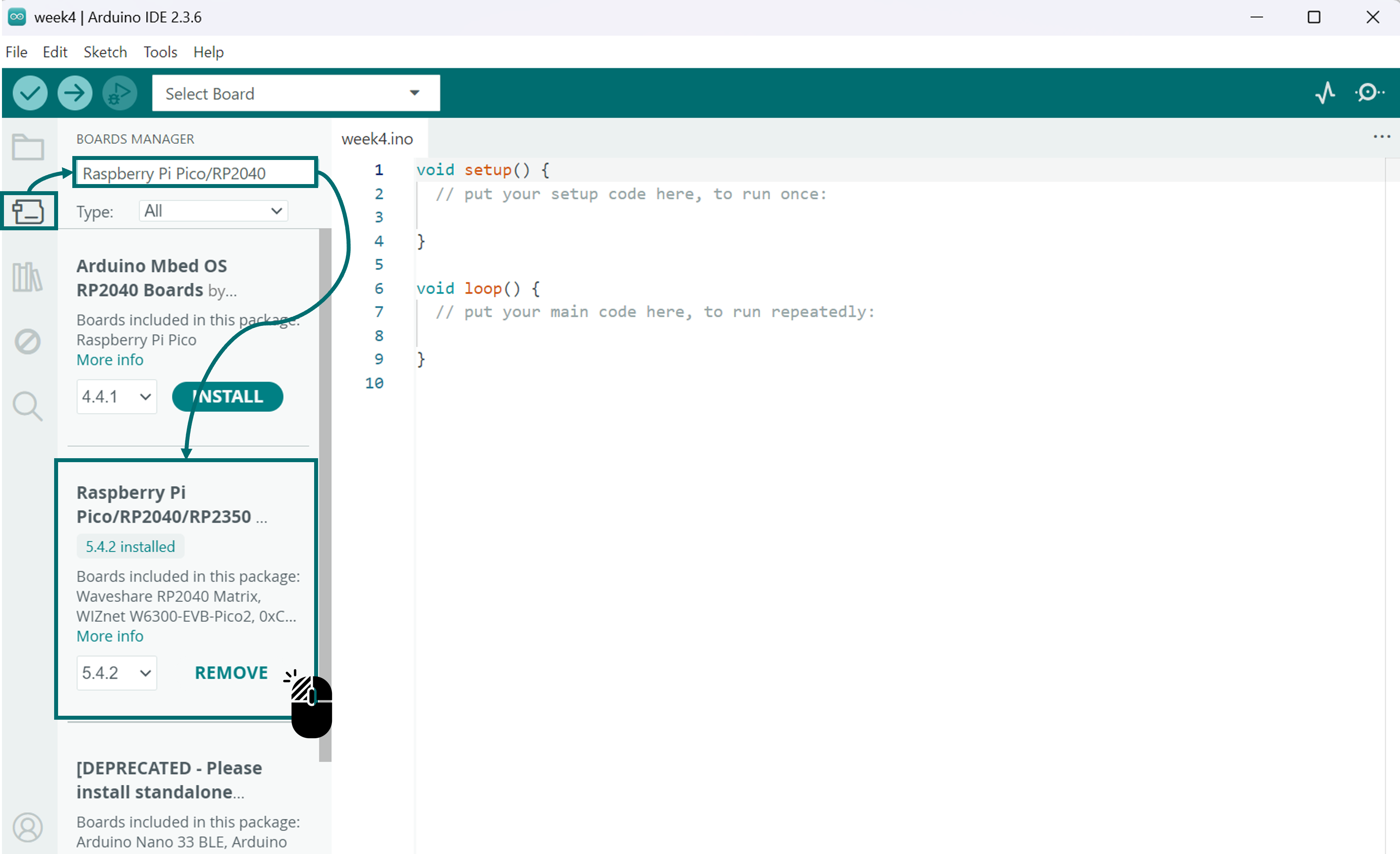
-
-
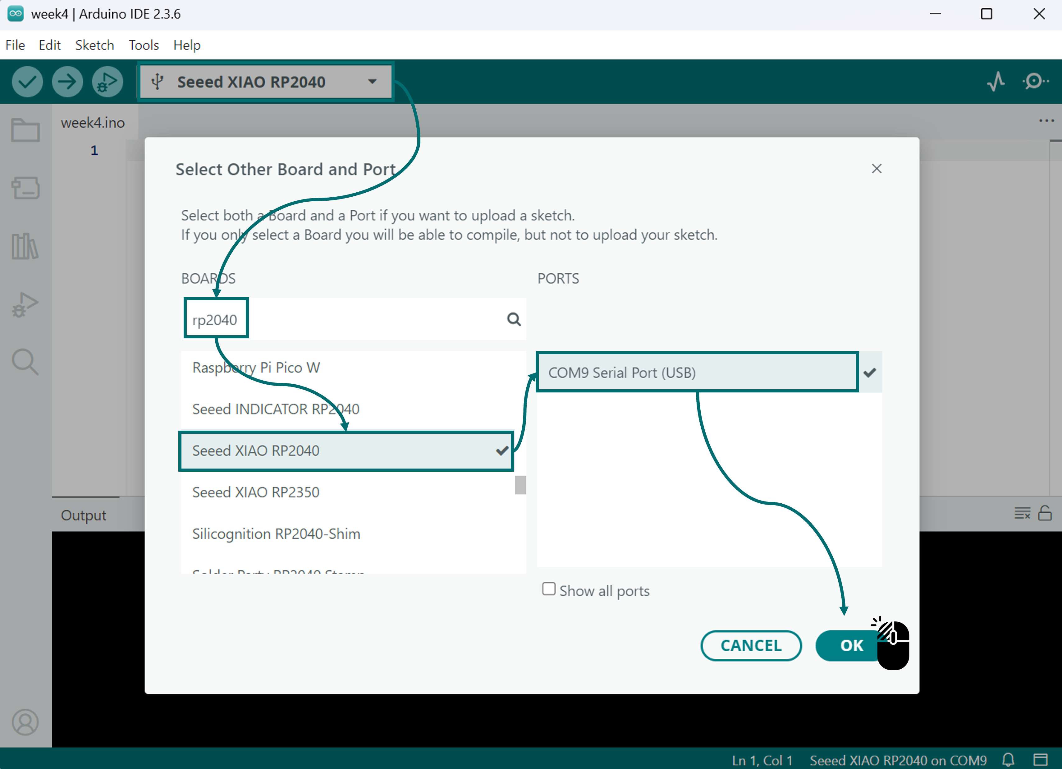
I selected the board and port: After installing the board package, I navigated to
🌐 Tools > Board, found "Seeed Studio XIAO RP2040", and selected it.
Now, the Seeed Studio XIAO RP2040 is fully set up for Arduino IDE and ready for programming. 😄
📝 Note: The setup process is pretty much the same for other microcontrollers too. Just make sure to check their installation guides and configuration details on their official pages.
💻 XIAO RP2040 Testing
To test the microcontroller, I decided to use an OLED Display as the output device. I used the XIAO RP2040 to show a simple image on the screen. Since the OLED can only interpret data in hexadecimal format, the image must first be converted before uploading it to the board.
📝 Note — Why Convert the Image to Hexadecimal?
OLED screens can't directly read image formats like JPG or PNG. Instead, they work with a sequence of numbers that define which pixels should be turned on or off. These numbers are grouped into bytes, and their position in the matrix determines the image's orientation. If the conversion is not done properly, the image might appear flipped, mirrored, or distorted on the display. Tools like image2cpp help adjust it to ensure it displays correctly on the screen.

📷 Image Preparation for OLED Display

-
Find suitable images:
It is recommended to use black-and-white images to simplify conversion and improve compatibility with the OLED screen.
-
Resize the image:
Adjust the image dimensions to fit the OLED screen resolution, ensuring that details remain visible. Paint or any image editing software can be used.
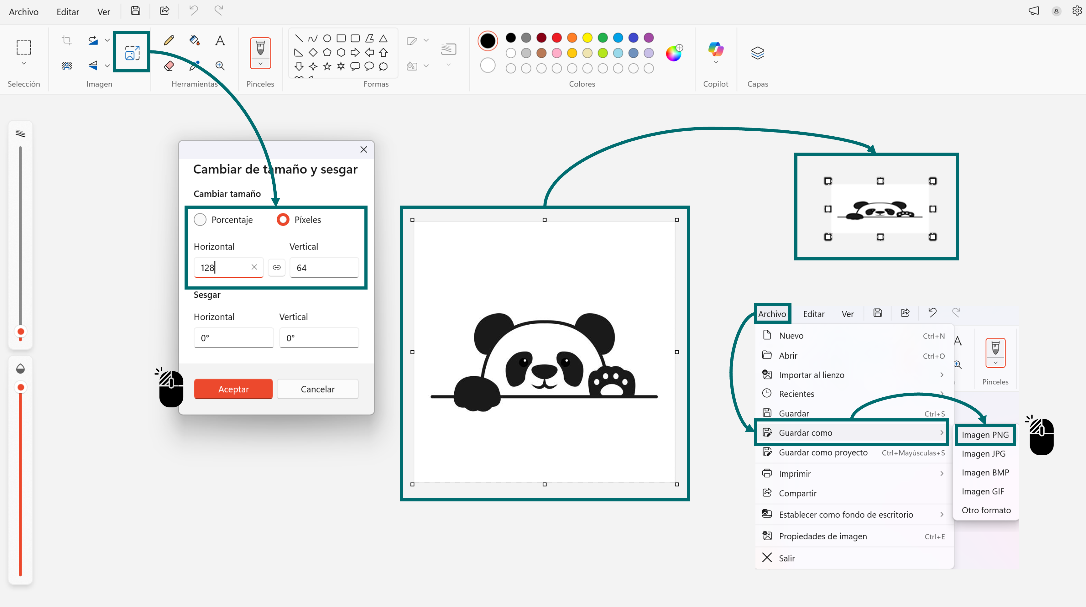
Image Resizing Process
-
Convert to BMP format:
Save the image as a monochrome BMP file to facilitate conversion to hexadecimal code.
-
Generate hexadecimal code:
After converting the image to black and white and resizing it to fit the OLED screen, the next step is to use the image2cpp tool to convert the BMP image into a hexadecimal number matrix that the microcontroller can interpret.- These are the settings that have been modified; the rest remain at their default values.
- Then, the code is generated.

Getting the image code from image2cpp

📝 Note: Visualize the complete code in Notepad++ or open the file in Notepad.
👀 This code is a section of the final program that will be used and uploaded through the Arduino IDE platform.
💻 WOKWI - Simulator
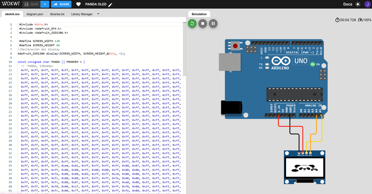
Before making the physical connections, I wanted to make sure my code worked properly. So, I tested it in the WOKWI online simulator.
-
Install the necessary libraries:
Install the required libraries to use the OLED screen (e.g., Adafruit GFX, Adafruit SSD1306). -
Import the generated hexadecimal code:
Copy the hexadecimal matrix generated by image2cpp into the Arduino code.

-
Connect the OLED display to the microcontroller:
Use the following connections:⬛GNDto ground🔴VCCto 3.3V🔵SDAto pin A4🟠SCLto pin A5📝 Note: SDA (Serial Data) is the line used to transmit data between the devices, while SCL (Serial Clock) provides the clock signal that keeps communication synchronized. Both lines form part of the I²C communication protocol used by the OLED display.
-
Adapt the code for the project:
Modify the code to fit the desired functionality.
- You can view the simulation at the following link: PANDA WOKWI
💻 Arduino IDE

After checking the simulation, I confirmed that both the code and the connections were correct. For the physical setup, I had to remember that on the XIAO RP2040, the I²C pins are SDA (D4) and SCL (D5). Once the wiring was done, I uploaded the same code from the Wokwi simulation to the board, and it worked perfectly.
📝 Note: To download the complete code in the Arduino IDE platform, click the button below.
- Here is the result: 😄
Final Thought
This week introduced me to new aspects of embedded programming. I focused on understanding how to set up the tools and how they interact with the board, which helped me see the full process from configuration to execution.
Working with two different boards and toolchains in the same week showed me that embedded programming is not a single approach. The tools, the language, and the workflow change depending on the architecture, and each setup works in a different way.
Reviewing the datasheet also helped me understand how the microcontroller is organized, especially the pin configuration and communication features. This is important for defining how components are connected and how the program interacts with them. For my final project, I will use the XIAO ESP32-S3 Sense and its WiFi capability to communicate with another device, which fits the requirements of my robot.
For this assignment, I built upon work started in the previous cycle while continuing its development this year. During the 2026 cycle, I expanded my understanding of different toolchains through the group assignment and learned more about the microcontroller selected for my final project.