
W5 | 3D Scanning and Printing
📝 Group Assignment:
- Test the design rules for your 3D printer(s)
- Document your work on the group work page and reflect on your individual page what you learned about characteristics of your printer(s).
What We Did
This week, as part of our group assignment, we tested some of the 3D printers available at the Fab Lab ESAN. The printers we used for the testers all operate with Fused Deposition Modeling (FDM) technology.
Our goal was to evaluate their performance by printing different test models that assess key parameters. We focused on the test models covered in class, which allowed us to analyze specific aspects of each printer's performance. These included:
A. Support tests — Evaluating overhang and clearance performance.
B. Unsupported tests — Analyzing how the printers handle angles, overhangs, and bridging without additional support.
C. Dimensional accuracy — Measuring whether the final prints match the intended design dimensions.
D. Surface finish — Observing the overall print quality, including layer smoothness and consistency.
We adjusted the printing parameters based on the recommended settings for each printer and material type. While some machines had predefined profiles that optimized these parameters, we also experimented with slight variations in some tests.
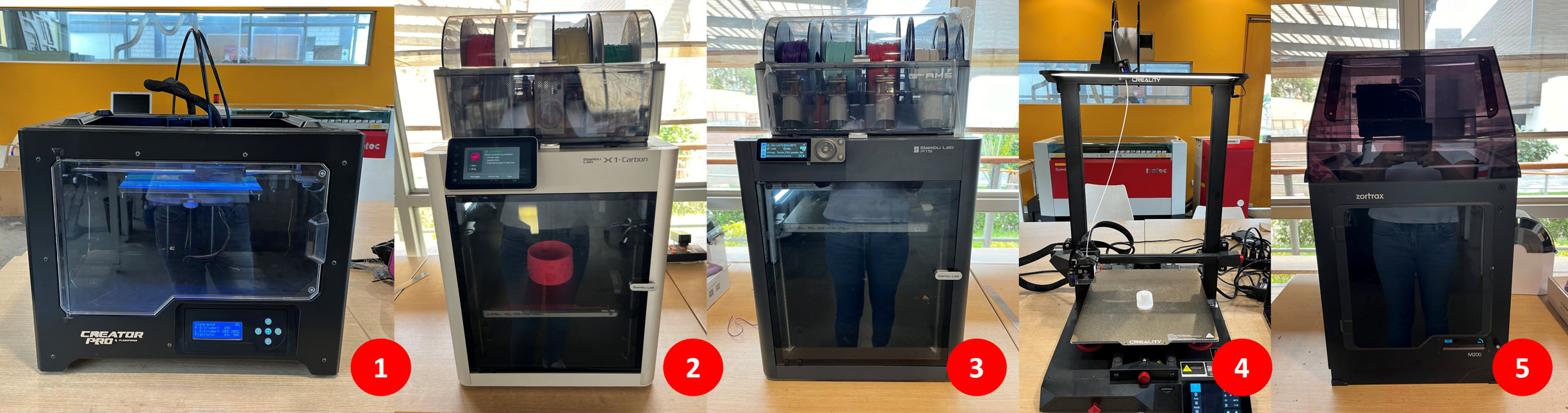
| N° | Brand | Model | Build Volume (mm) | Material | Other Considerations |
|---|---|---|---|---|---|
| 1 | Flashforge | Creator Pro | 227 × 148 × 150 | PLA | Dual extruder, enclosed chamber for better temperature control. |
| 2 | Bambu Lab | X1 Carbon | 256 × 256 × 256 | PLA | Fully enclosed, high-speed printing, automatic calibration, AI-assisted print monitoring, multi-color printing with AMS system, touchscreen interface. |
| 3 | Bambu Lab | P1S | 256 × 256 × 256 | PLA | Fully enclosed, high-speed printing, multi-color printing with AMS system. |
| 4 | Creality | CR-10 Smart Pro | 200 × 200 × 180 | PLA | Large build volume, all-metal direct drive extruder, auto-leveling. |
| 5 | Zortrax | M200 | 300 × 300 × 400 | ABS | Closed ecosystem with Z-Suite software, optimized for ABS printing. |
The Design Rules for the Printers
To determine the design rules for the 3D printers, we conducted a series of standardized tests that Neil taught in class. These tests help evaluate the capabilities and limitations of each printer in handling different design challenges. The tests include Support tests, Unsupported tests, Dimensional accuracy and Surface finish.
To ensure consistency, we used the same printing parameters across all machines, with slight variations for the Zortrax M200, which prints with ABS instead of PLA. Additionally, each printer operates with different slicing software, which can influence the final print quality and settings adjustments.
The general printing characteristics were:
Nozzle Diameter: 0.4 mm
Filament Diameter: 1.75 mm
Extruder Temperature: 205°C
Bed Temperature: 55°C
The table below summarizes the parameters used for each printer, including slicer software, material type, and any specific modifications made during testing:
| N° | 3D-Printer | Slicer | Material | Color | Quality | Thickness | Infill | Adhesion |
|---|---|---|---|---|---|---|---|---|
| 1 | Creator Pro | FlashPrint | PLA | Silver | 0.20 Standard | 2 | 15% Grid | No |
| 2 | Bambu Lab X1 Carbon | Bambu Studio | ePLA-Matte | Orange | 0.20 Standard | 2 | 15% Grid | No |
| 3 | Bambu Lab P1S | Bambu Studio | ePLA-Matte | Strawberry | 0.20 Standard | 2 | 15% Grid | No |
| 4 | CR-10 Smart Pro | Creality Slicer | PLA | White | 0.20 Standard | 2 | 15% Grid | No |
| 5 | M200 | Z-Suite | Z-ABS | Black | 0.19 Normal | 2 | 20% Grid | Yes |
A Support Tests: Evaluating Overhang and Clearance Performance
For support tests, we evaluate how well a printer handles overhangs and fine clearances. These tests help determine the effectiveness of support structures, their ease of removal, and their impact on the final print quality.
For the Overhang Test, we evaluated the printer's ability to produce overhangs with support structures, focusing on ease of removal and surface quality. After printing, we removed the supports and inspected the parts for defects like sagging, rough textures, or excess material.
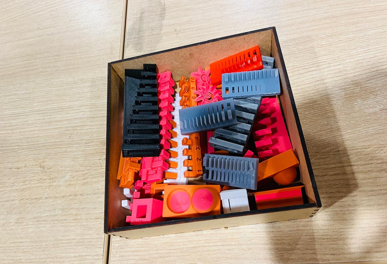
After printing with support and using the previously mentioned parameters, we obtained the following samples.
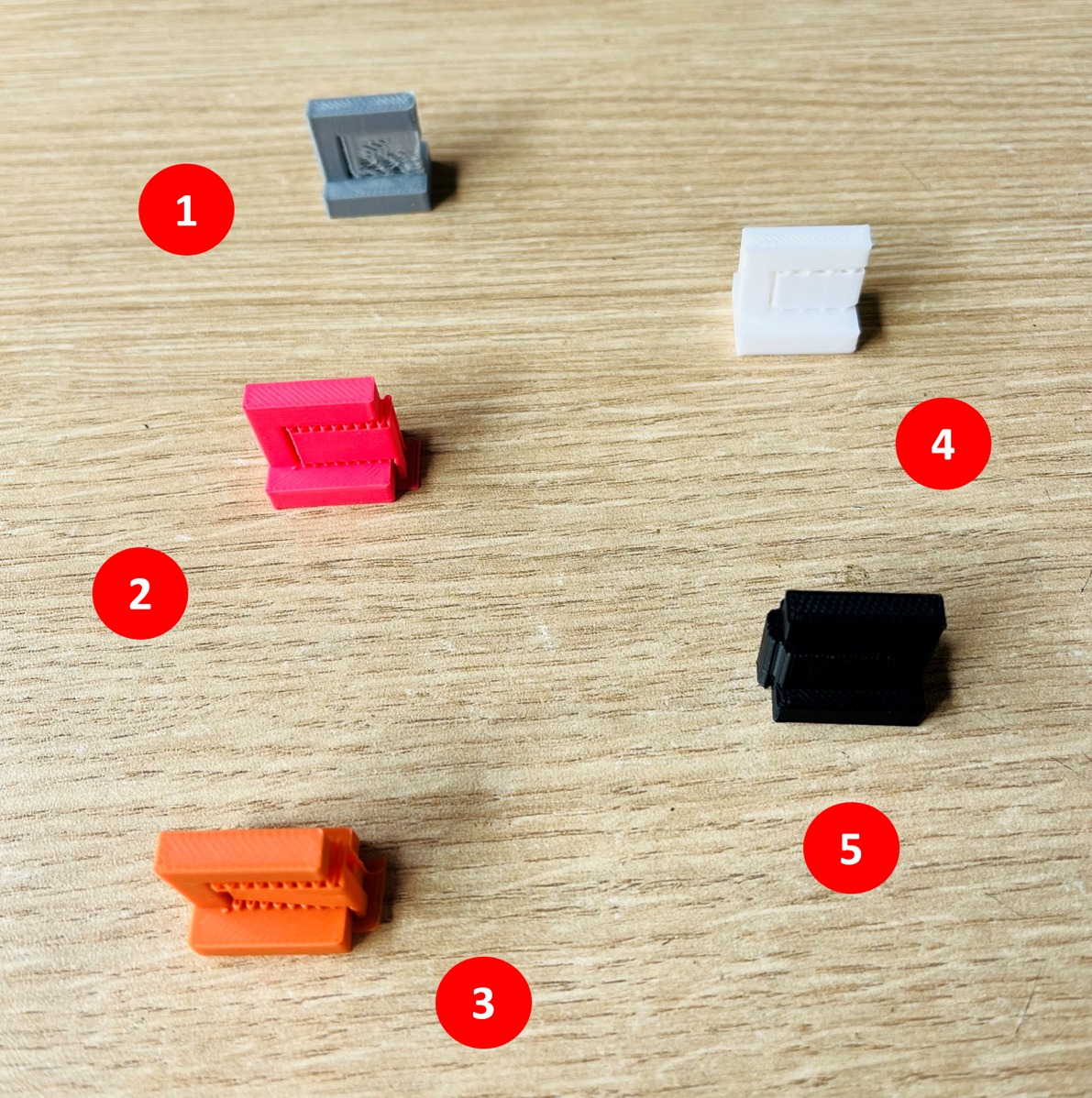
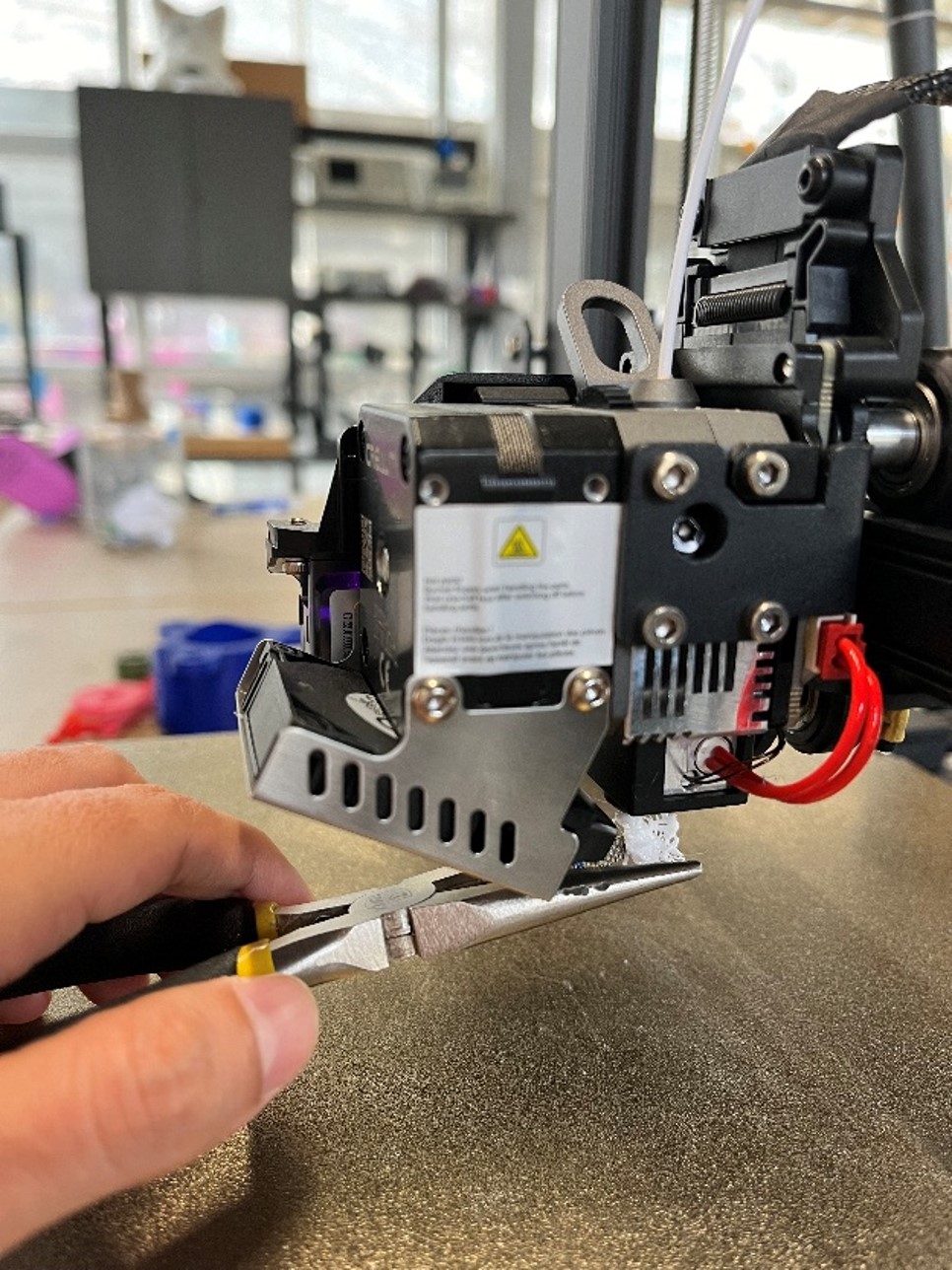
Then, we carefully removed the supports using needle-nose pliers. We observed the following results:

Observations by Printer
Creator Pro
Support removal was difficult, even with pliers.
Residual filament adhered to the underside of the overhang, leaving rough textures and excess material.
Bambu Lab X1 Carbon & P1S
Support removal was very easy and didn't require pliers.
No excess material was left behind.
Slightly visible lines where the supports were attached, but overall, clean results.
Creality CR-10 Smart Pro
Support removal was easy with pliers.
No excess material remained.
The surface was clean, but the support lines were still visible.
Zortrax M200
Support removal was easy with pliers.
No significant excess material, but some filament adhered to the base of the overhang.
Support lines were slightly visible.
Final Comments
For prints requiring overhangs with support structures, Bambu Lab X1 Carbon and P1S provide the best results with minimal effort in post-processing.
For the Clearance Test, we tested the printer's precision in maintaining gaps between adjacent parts. After removing the supports, we checked the fit and movement to determine the minimum clearance needed for free movement without fusing. This is crucial for optimizing tolerances in functional prints.
After printing with support and using the previously mentioned parameters, we analyzed the results.
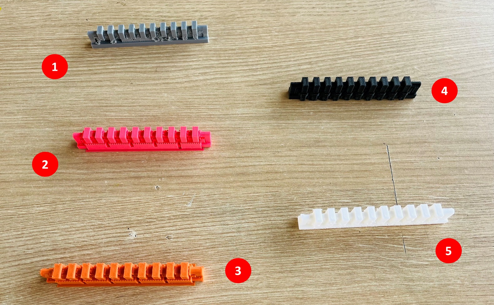
Then, we carefully removed the supports using needle-nose pliers. We observed the following results:

Observations by Printer
FlashForge Creator Pro
Movement range: 0.4 mm to 1 mm, but some jamming due to filament residue.
No movement: 0.1 mm to 0.3 mm.
Surface finish: Poor, with noticeable support remnants and a rough texture.
Bambu Lab X1 Carbon
Movement range: 0.3 mm to 1 mm without issues.
Requires force: 0.2 mm (slight force), 0.1 mm (no movement).
Surface finish: Smooth, but visible layer lines.
Bambu Lab P1S
Movement range: 0.4 mm to 1 mm without issues.
Requires force: 0.3 mm (slight force), 0.2 mm (more force), 0.1 mm (no movement).
Surface finish: Smooth, with visible layer lines.
Creality CR-10 Smart Pro
Movement range: 0.4 mm to 1 mm without issues.
Requires force: 0.3 mm (slight force), 0.2 mm (more force), 0.1 mm (no movement).
Surface finish: Not rough, but layer lines are more pronounced compared to Bambu Lab printers.
Zortrax M200
Movement range: 0.6 mm to 1 mm without issues.
Requires force: 0.5 mm (minimal force), 0.4 mm (moderate force), 0.3 mm to 0.1 mm (no movement).
Surface finish: Generally smooth, but very noticeable marks left by the supports at the base.
Final Comments
For functional prints requiring precise tolerances, Bambu Lab X1 Carbon and P1S are the most reliable choices, as they achieved smooth movement at lower clearances with minimal post-processing issues.
B Unsupported Tests: Evaluating Angle, Overhang, and Bridging Performance
For unsupported tests, we evaluated how each printer handled overhangs, angles, and bridges without additional support structures. These tests are essential to understanding the printer's ability to maintain print quality when it comes to unsupported features.
For the Angle Test, we printed a model with tilts ranging from 0° to 90° in 10° increments. This test allowed us to evaluate how well each printer handled steep angles without support, observing the point at which the layers began to lose adhesion, and the characteristic "spaghetti" effect formed.
After printing without support and using the previously mentioned parameters, we analyzed the results.
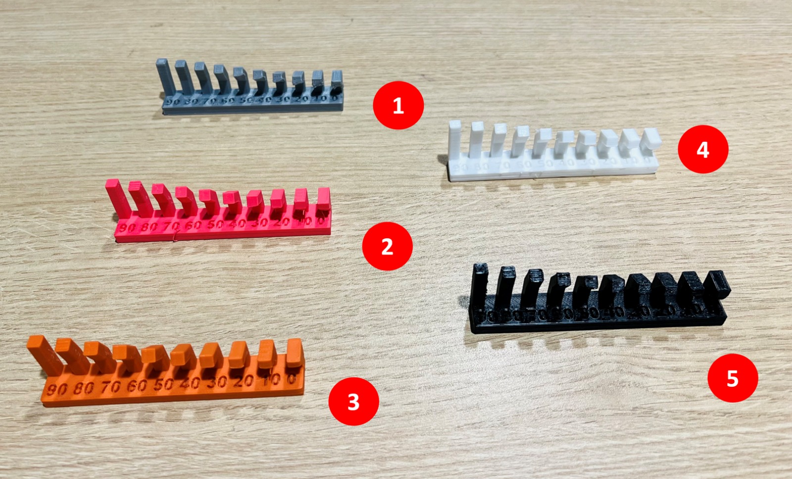
Upon observation, we noticed the following:
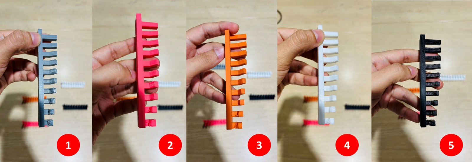
Observations by Printer
Creator Pro
0° to 10°: Visible sagging and noticeable "spaghetti" formation.
20° to 50°: Some inclinations on one side, but no filament detachment.
60° to 90°: Printed successfully with no issues.
Bambu Lab X1 Carbon & P1S
0° to 10°: Minor filament strands visible.
20°: Slight inclination.
30° to 90°: Printed successfully with no defects.
Creality CR-10 Smart Pro
Performance identical to the Bambu Lab printers, handling angles well.
Zortrax M200
0° to 10°: Minor sagging, with some filament strands visible.
20° to 30°: Slight inclinations noticeable.
40° to 90°: Printed successfully with no major defects.
Final Comments
Overall, for prints requiring steep angles without supports, the Bambu Lab X1 Carbon, P1S, and Creality CR-10 Smart Pro are the most reliable options, while the Creator Pro and Zortrax M200 may need adjustments to improve performance at lower angles.
For the Overhang Test, we printed a model with incremental overhangs ranging from 1mm to 10mm. This allowed us to determine the point at which the print began to fail, observing when the layers began to lose stability before reaching the stage where sagging or "spaghetti" formation occurred.
After printing without support and using the previously mentioned parameters, we analyzed the results.
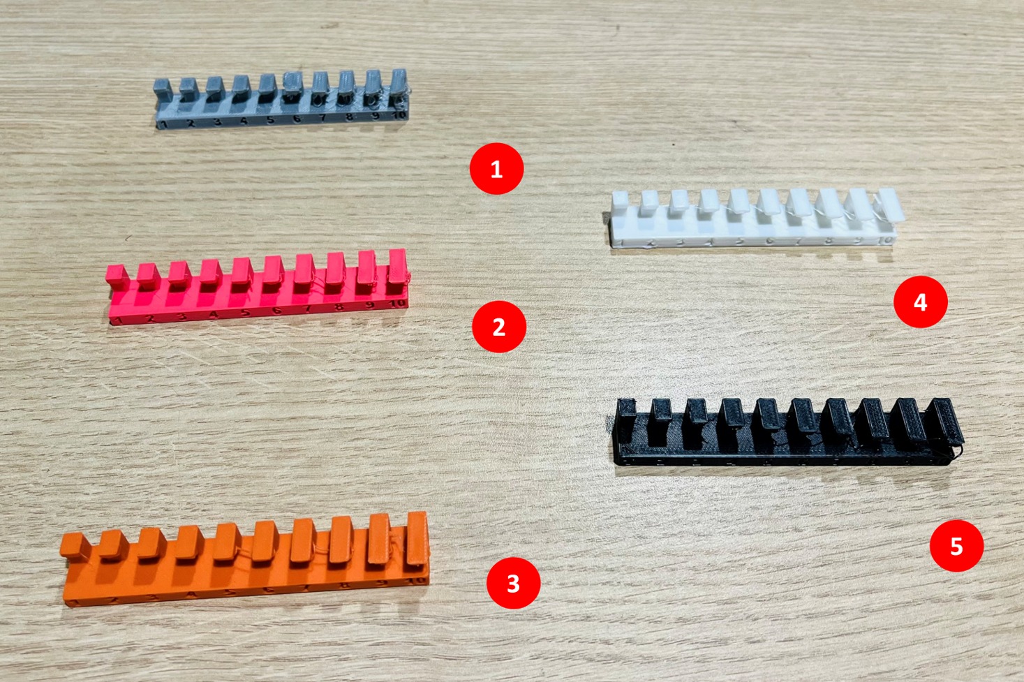
Upon observation, we noticed the following:
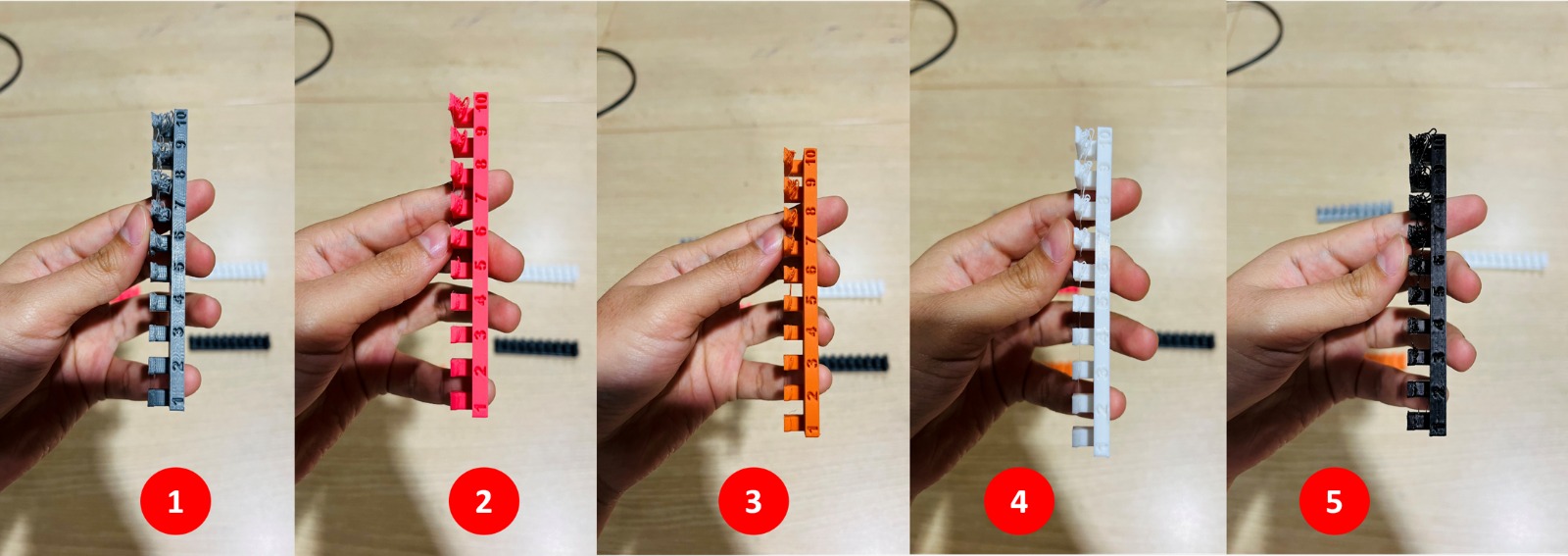
Observations by Printer
Creator Pro
From 1 mm to 5 mm, no significant sagging, but filament was slightly misaligned and overlapped.
At 5 mm, some filament strands started to detach.
By 10 mm, sagging was highly pronounced, with visible "spaghetti" formation.
Bambu Lab X1 Carbon & P1S
Overhangs were stable up to 6 mm, where slight sagging began.
The sagging increased gradually but was not as severe as in the Creator Pro.
At 10 mm, some minor deformations appeared, but overall print quality remained better.
Creality CR-10 Smart Pro
Sagging started at 6 mm, progressively increasing.
By 10 mm, the deformation was more visible than in the Bambu Lab printers but still less pronounced than in the Creator Pro.
Zortrax M200
Sagging began as early as 5 mm, increasing gradually.
At 10 mm, the print showed significant sagging, almost at the same level as the Creator Pro.
Final Comments
The Bambu Lab X1 Carbon, P1S, and Creality handled overhangs better than the Creator Pro and Zortrax M200, with less visible sagging at longer overhangs.
The Creator Pro and Zortrax M200 struggled significantly, with heavy filaments drooping at 10 mm, indicating that their cooling systems or overhang handling settings may need adjustments.
For the Bridging Test, we assessed how well each printer could span gaps between two points without support structures. The model used included bridges ranging from 2 mm to 20 mm, increasing in 2 mm increments. By analyzing the results, we were able to determine the maximum distance each printer could handle before the filament began to not adhere properly.
After printing without support and using the previously mentioned parameters, we analyzed the results.
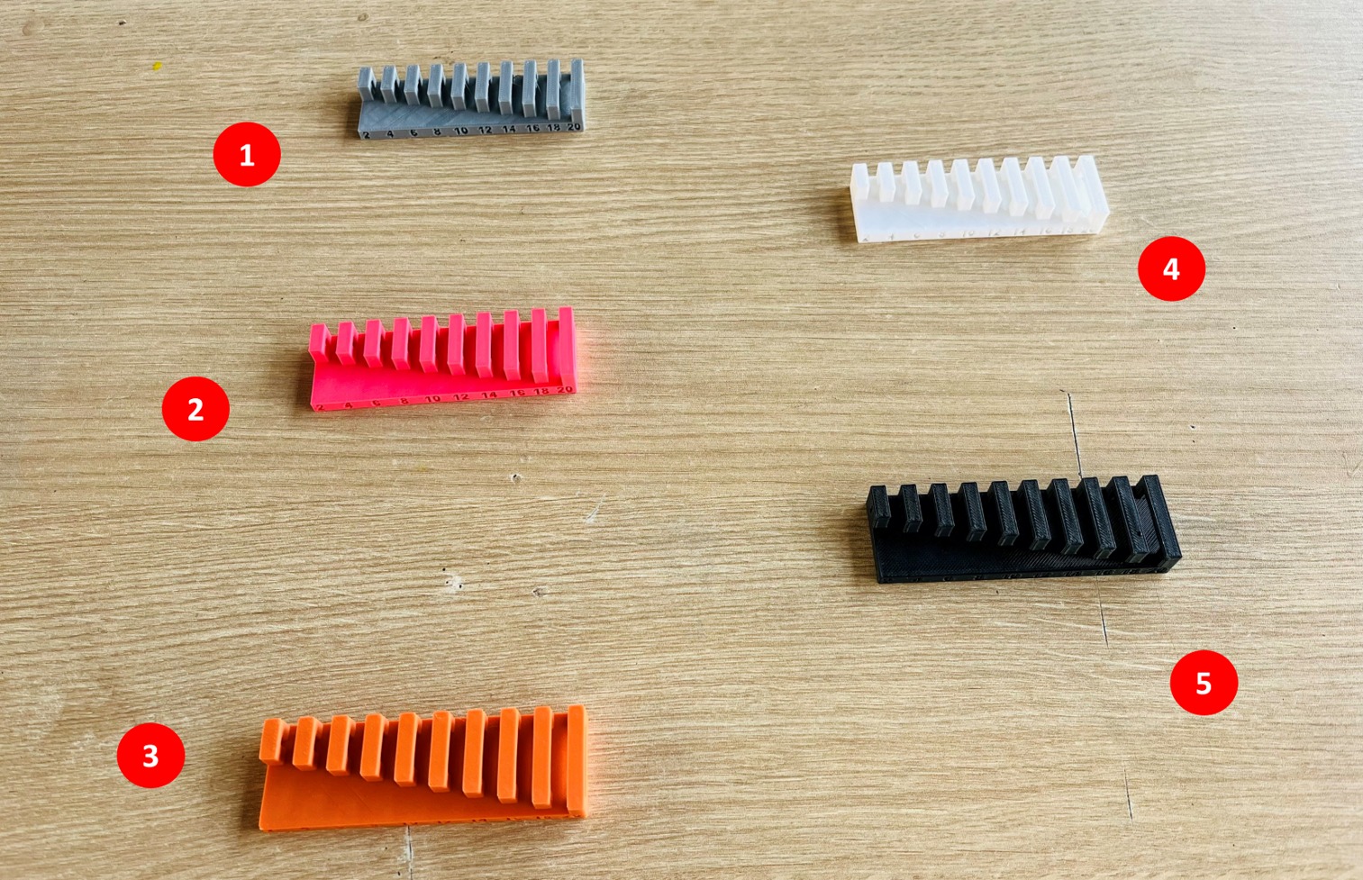
Upon observation, we noticed the following:
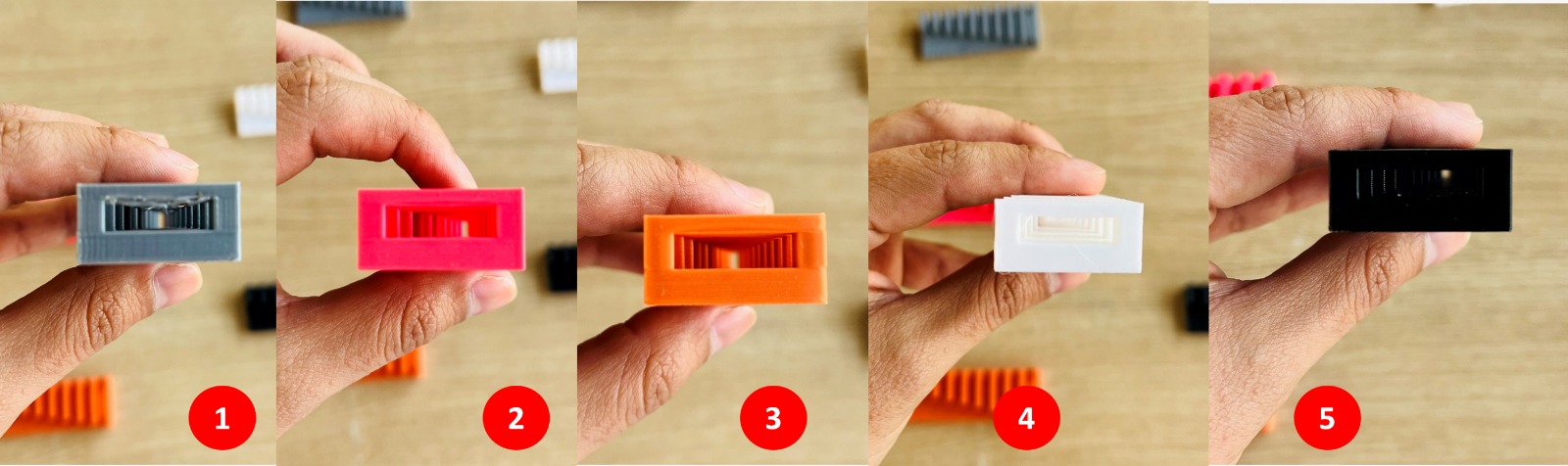
Observations by Printer
Creator Pro
Up to 6 mm, the bridges printed well.
From 8 mm, slight sagging started appearing, increasing noticeably at 12 mm.
At 14 mm, sagging became more pronounced.
At 20 mm, the defects were highly visible.
Bambu Lab P1S & X1 Carbon
No visible filament sagging across most of the test.
At 20 mm, the lines were slightly misaligned and had a minor downward inclination.
Creality CR-10 Smart Pro
No significant sagging until 18 mm, where some filament drop was observed.
At 20 mm, the bridge showed noticeable misalignment with a slight downward inclination.
Zortrax M200
Performed similarly to the P1S and X1 Carbon, maintaining good bridge quality throughout the test.
Final Comments
These results suggest that cooling efficiency and extrusion precision play a crucial role in bridging performance. Printers with stronger part cooling fans and optimized bridging settings managed to maintain better results across longer distances.
C Dimensional Accuracy Test
For the Dimensional Accuracy Test, we printed a model featuring an external square of 20 mm and an internal square of 10 mm. This test allowed us to evaluate how precisely each printer replicated the intended dimensions. After printing, using the previously mentioned parameters, we analyzed the results.
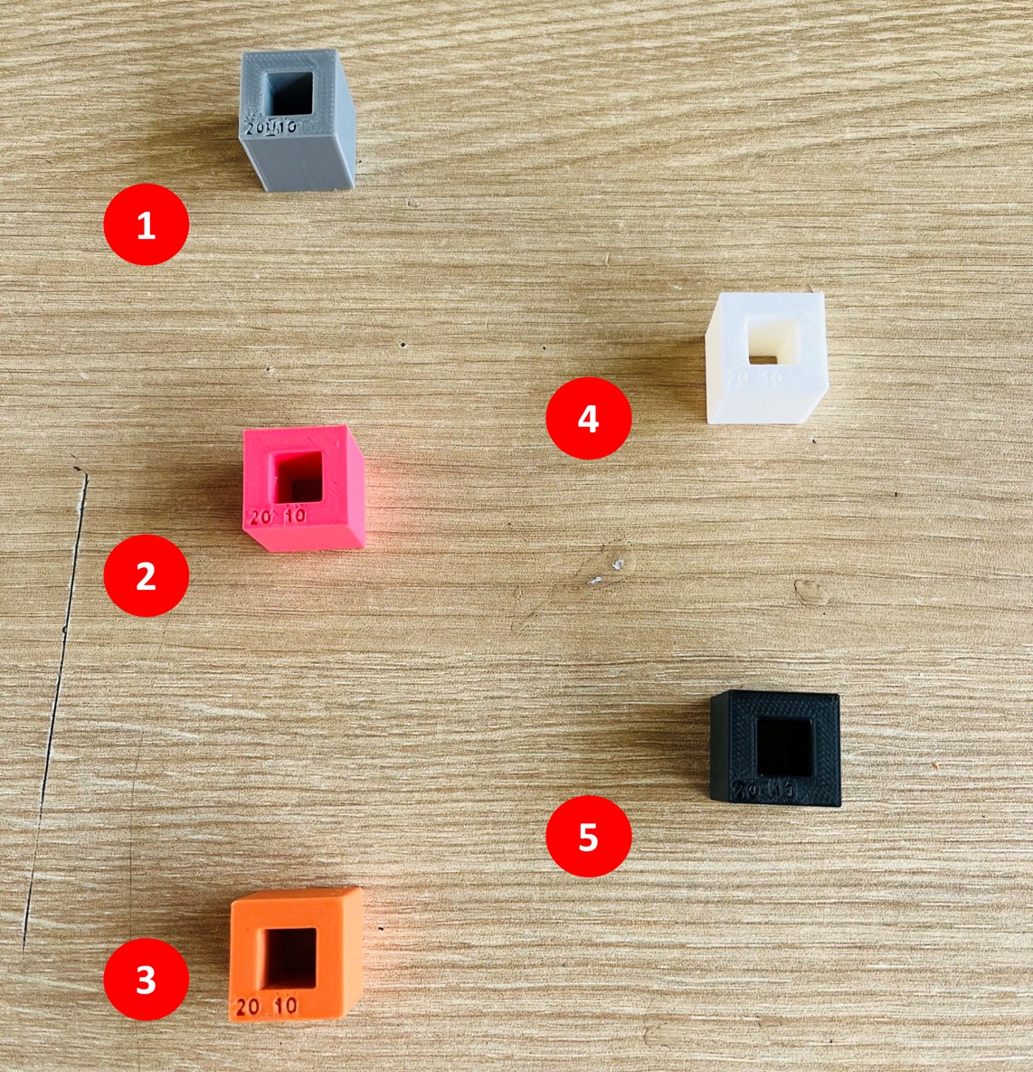
Upon observation, we noticed the following:
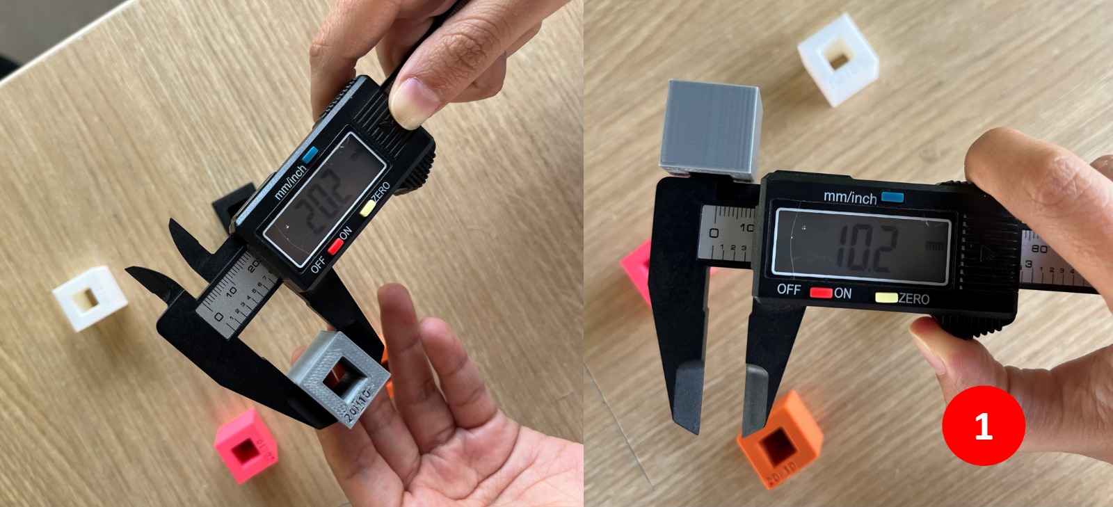
1. Creator Pro
External: 20.2 mm — Internal: 10.2 mm — slightly oversized.
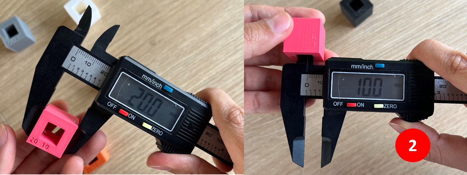
2. Bambu Lab X1 Carbon
External: 20 mm — Internal: 10 mm — perfect match.
3. Bambu Lab P1S
External: 19.9 mm — Internal: 10.1 mm — minor deviation.
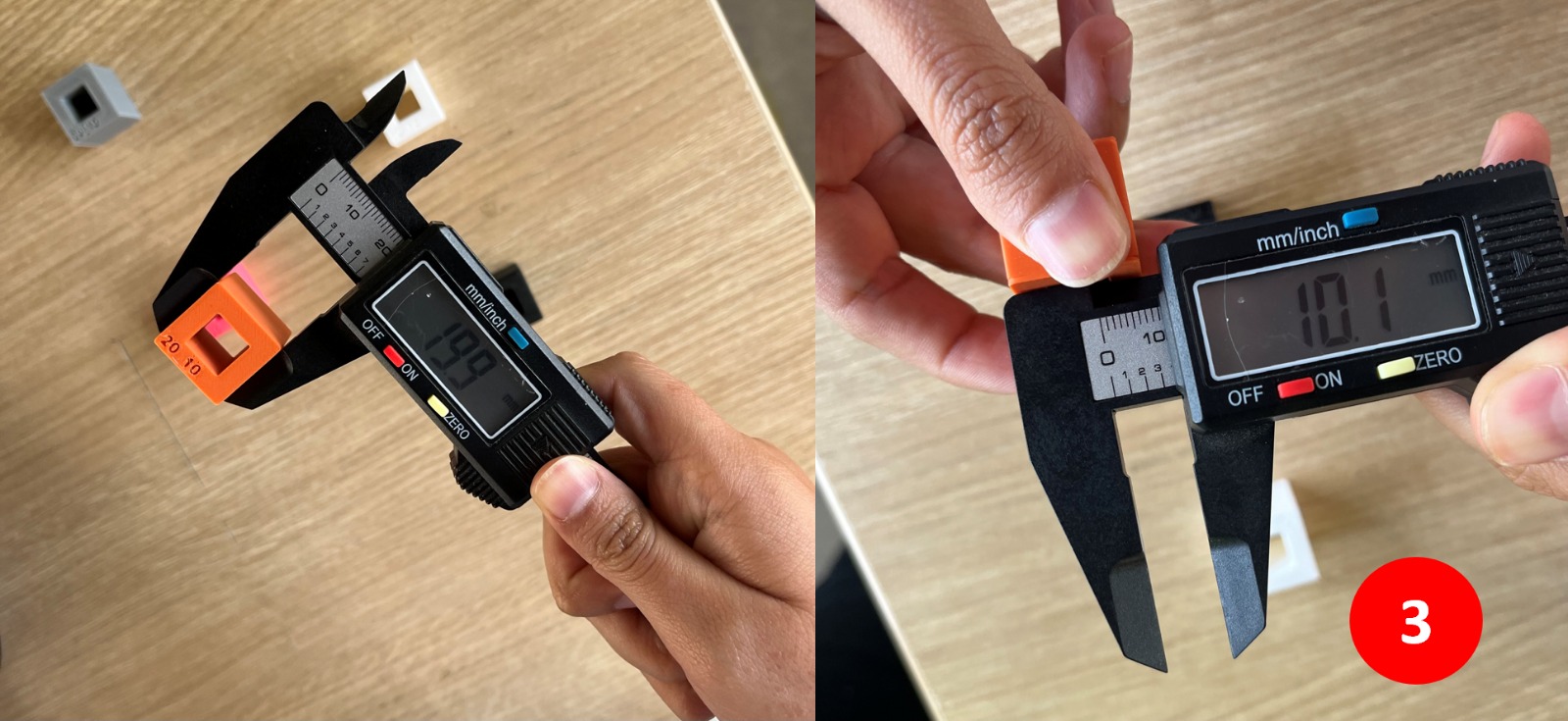
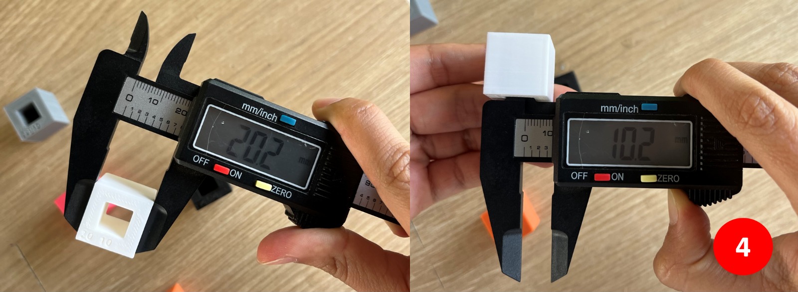
4. Creality CR10 Smart Pro
External: 20.2 mm — Internal: 10.2 mm — slightly oversized, similar to Creator Pro.
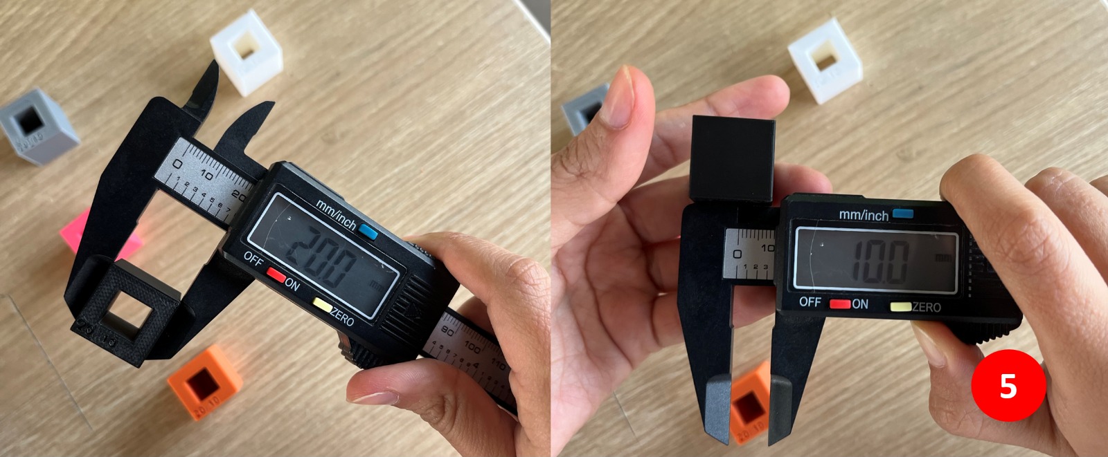
5. Zortrax M200
External: 20 mm — Internal: 10 mm — perfect match.
Key Observations
Bambu Lab X1 Carbon & Zortrax M200
Provided the most precise results, accurately matching the intended dimensions.
Bambu Lab P1S
Very close to the target dimensions, with a slight variation possibly due to slicer settings or material flow.
Creator Pro & Creality
Printed the model slightly larger than designed, possibly due to material expansion or minor calibration differences.
Final Comments
This test highlights how different 3D printers handle dimensional accuracy. Some printers produce results that are closer to the design, while others may require minor adjustments to improve precision. If accuracy is crucial for a project, it's important to fine-tune the printer settings and account for these small variations in size.
D Surface Finish Test
For the Surface Finish Test, we evaluated the quality and smoothness of printed surfaces by analyzing both concave and convex geometries. The model included a hemispherical dome and a matching cavity, allowing us to observe layer adhesion, surface uniformity, and the presence of any visible artifacts such as layer lines or rough textures. This test provided insights into the overall print resolution and how different printers handled curved surfaces.
For this test, we used standard print quality with a 0.20 mm layer height. The only exception was the M200, where the closest available setting was normal quality with a 0.19 mm layer height.
We conducted the same test on all printers, except for the X1 Carbon. After multiple trials, we observed that its print quality closely matched that of the P1S, so we carried out a different type of testing for this printer. After printing, using the previously mentioned parameters, we analyzed the results.
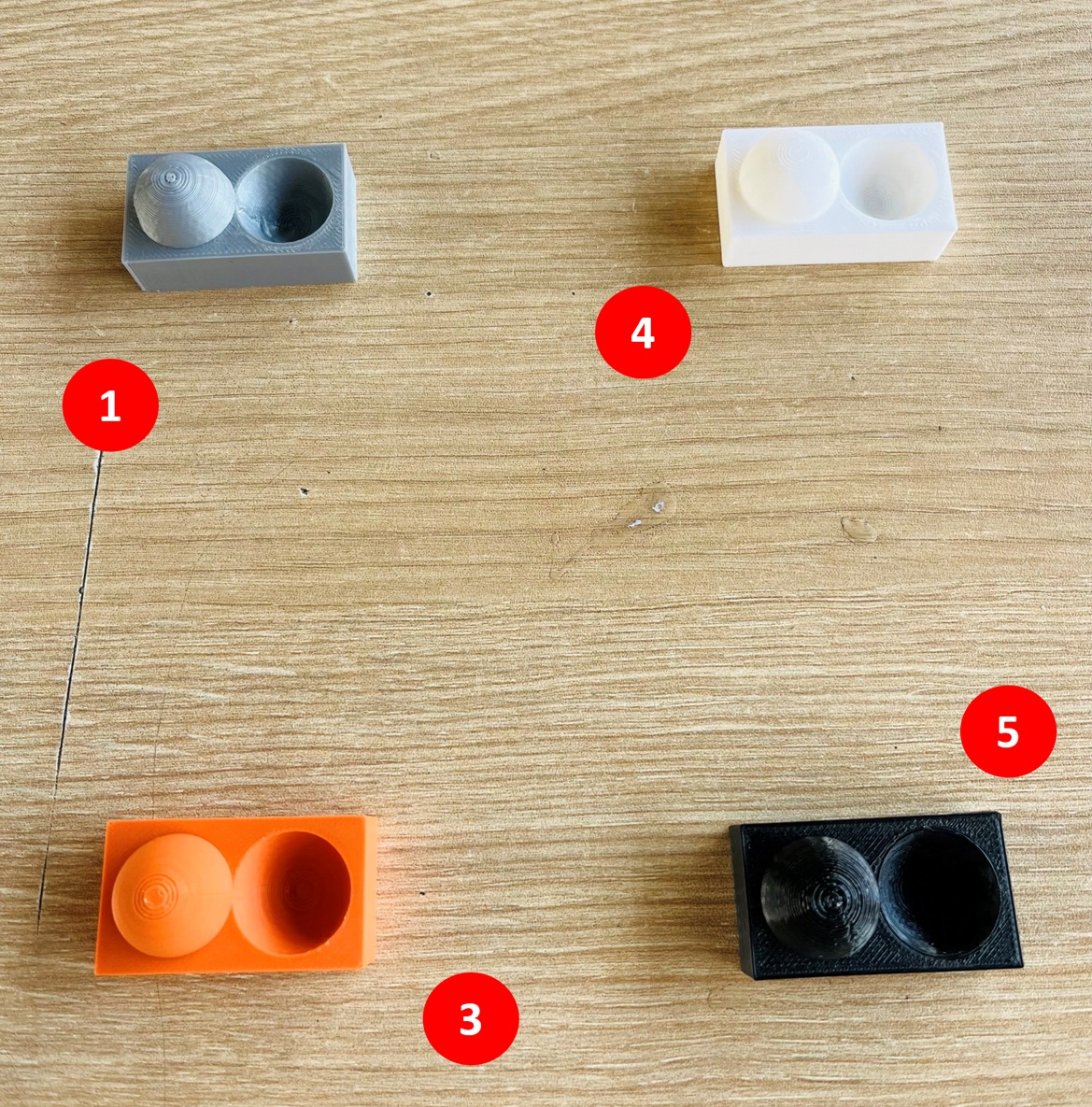
Upon observation, we noticed the following:
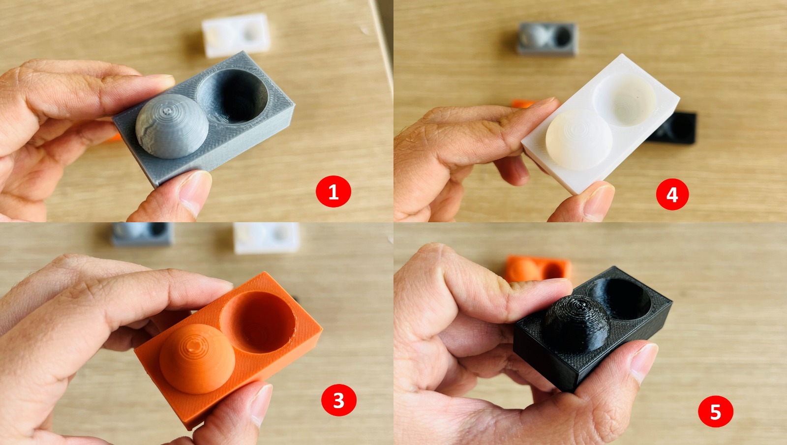
Key Observations
Creator Pro & Creality
The layer lines were quite pronounced, making the surface texture rougher.
Bambu Lab P1S
The layer lines were slightly less visible compared to Creator Pro and Creality, resulting in a smoother finish.
Zortrax M200
Surprisingly, the layer lines appeared more pronounced than expected, even though this printer is known for its good print quality.
Bambu Lab X1 Carbon
As previously mentioned, this printer was used for a different test due to its similar performance to the P1S.
Why Did Zortrax Show More Pronounced Layer Lines?
One possible reason for the more visible layer lines on the Zortrax M200 is the material used — ABS. ABS tends to shrink as it cools, which can lead to more noticeable layer lines, especially on curved surfaces.
Final Comments
If surface finish is a priority, adjusting layer height and fine-tuning print settings can help achieve better results.
E A New Surface Finish Test
The new test we conducted involved varying the layer height. For this, we used the X1 Carbon printer and its Bambu Studio slicer, which allowed us to configure the model so that the highest and lowest parts of the spherical section were printed in different colors (Strawberry PLA) while also having a layer height of 0.08 mm.
Steps for the Layer Height and Color Variation Test
1. Selecting the Printer and Slicer
We used the Bambu Lab X1 Carbon and its slicing software, Bambu Studio, which allowed us to configure different layer heights and colors within the same print.
2. Configuring Layer Heights and Colors
The upper and lower parts of the spherical section were assigned different colors (Strawberry PLA) to help visually distinguish the variations in layer thickness.
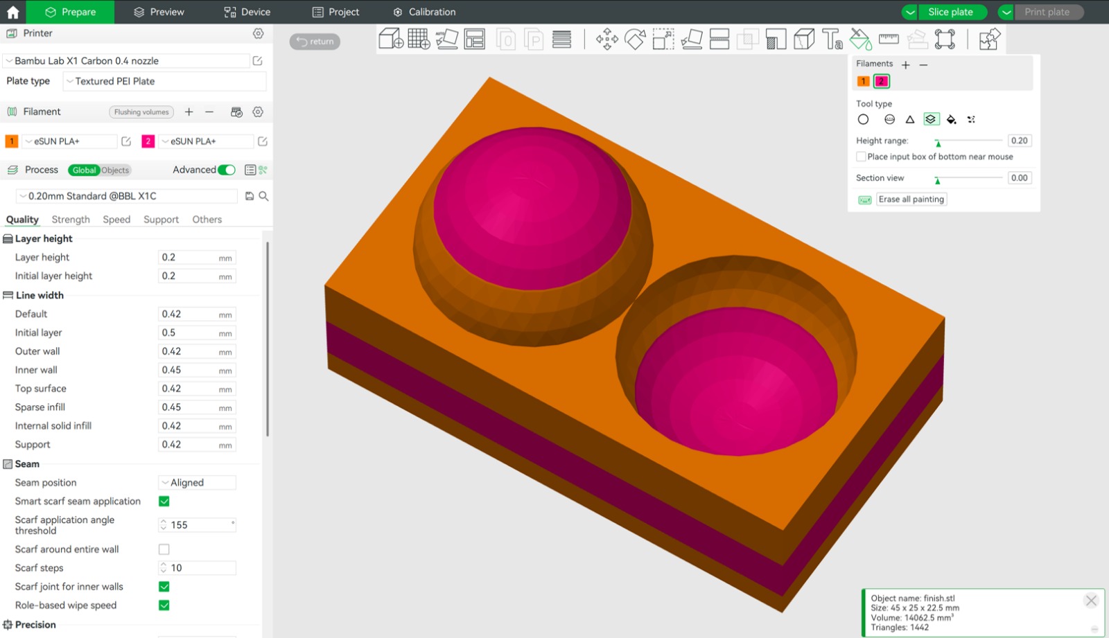
A layer height of 0.08 mm was applied to these areas, while the rest of the model maintained a standard layer height.
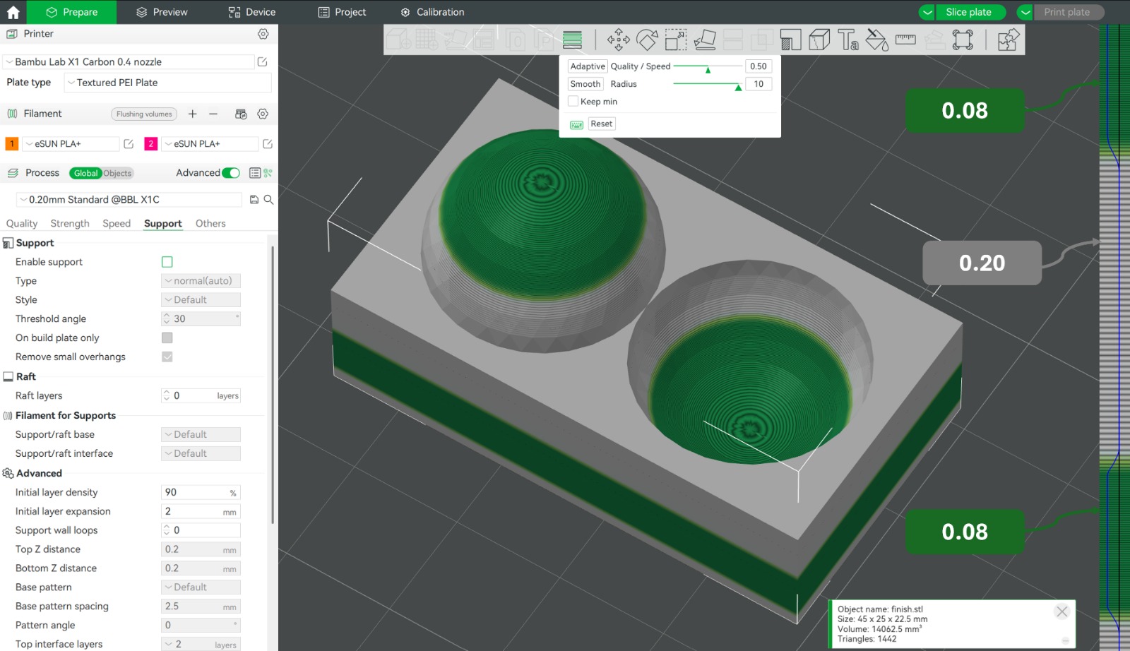
3. Printing Process
The print was executed with the defined settings, ensuring a clear transition between different layer heights.
4. Observing the Results
The regions with 0.08 mm layers displayed a noticeably smoother surface, reducing visible layer lines and enhancing detail in curved areas.
The variation in layer height demonstrated a balance between fine detail and overall print efficiency.
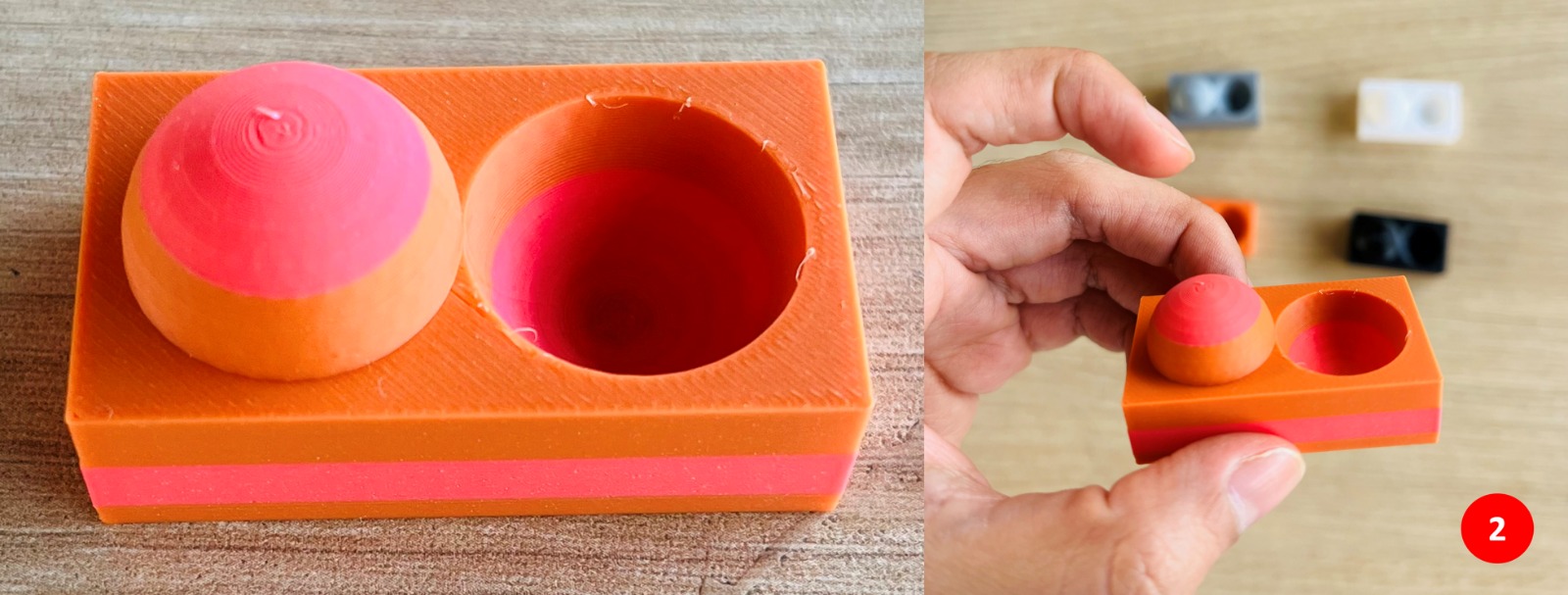
Final Comments
This test confirmed that reducing layer height significantly improves surface quality, particularly in curved geometries. The finer layers resulted in smoother textures, making this approach ideal for prints where aesthetics and detail are critical.
F "Spaghetti Appears" 🍝
During one of our test prints on the CR-10 Smart Pro, we ran into a little disaster — our print turned into a tangled mess of filament, looking more like a plate of spaghetti than anything else!
Halfway through, the filament got stuck in the extruder, causing it to stop feeding properly. Instead of smooth layers, the printer kept pushing out filament that had nowhere to go, creating a big, stringy mess.
To fix it, we stopped the print, carefully removed the jammed filament from the nozzle, and made sure everything was clear. Once we restarted the print, everything went smoothly, and the model printed just fine.
Lesson learned: Regularly checking and maintaining the extruder is essential to avoid filament jams and ensure a good printing experience!
💡 What I Learned from Testing the 3D Printers
Working with a variety of printers — from open-frame machines to fully enclosed systems — gave me a clear view of how hardware influences the final result in FDM printing. While printer specifications give an initial idea of capabilities, the differences become more evident when comparing printed parts directly. Factors such as chamber design, automatic calibration, and extrusion systems all contribute to print quality, and these differences became more apparent throughout the tests.
One aspect that stood out to me was surface finish. Layer lines have traditionally been one of the most visible limitations of FDM printing, but the results from the Bambu Lab printers showed how much this has improved. The layer lines were barely noticeable, achieving a level of surface quality that would have been difficult to obtain with earlier FDM systems. Their higher printing speed was also apparent compared to the other machines, making them a practical option when both quality and efficiency are required.
Beyond the hardware comparison, the tests themselves were a practical way to understand the fundamentals of FDM printing. Working through support structures, dimensional accuracy, and surface finish made these concepts concrete — each test revealed why these parameters matter and how they affect the final result in ways that are difficult to fully understand without hands-on experience.
📝 Individual Assignment:
- Design, document and 3D print an object (small, few cm3, limited by printer time) that could not be easily made subtractively
- 3D scan an object (and optionally print it)
Design and 3D Print Test
Small Gyroscope
For this week's individual assignment, I challenged myself to design and 3D print an object that could not be easily made using traditional subtractive methods. After brainstorming several ideas, I decided to design a small gyroscope—a mechanism made up of multiple concentric rings that rotate freely within each other. I chose this design because its moving parts can be printed directly in place, making it a good example of a geometry that benefits from additive manufacturing.
Why This Geometry Benefits from Additive Manufacturing
The gyroscope's concentric ring structure presents some challenges for traditional subtractive manufacturing methods.
Undercuts
The outer rings partially obstruct access to the inner geometry, making it more difficult for cutting tools to reach certain areas without additional setups or manufacturing steps.
Nested moving parts
The rings are designed to rotate within one another with small clearances between them. Manufacturing these components separately and assembling them afterwards would require careful alignment and additional assembly operations.
Because of these characteristics, additive manufacturing offers a practical way to produce the gyroscope as a single functional part, with all of the moving elements created during the printing process and no post-assembly required.
Designing in Autodesk Fusion
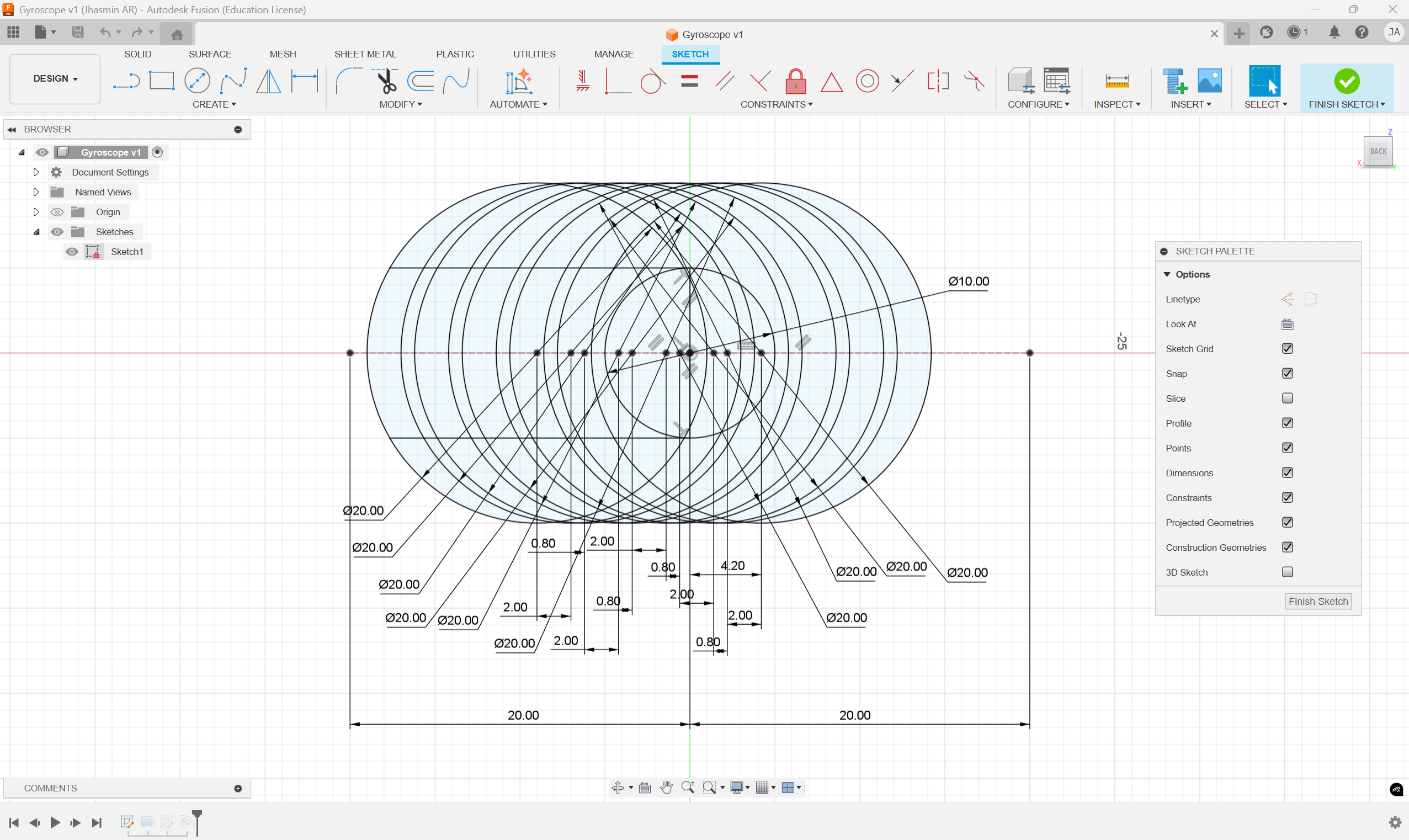
I modeled the gyroscope in Autodesk Fusion using a single sketch as the base for all the geometry. The sketch defines the full ring layout: a total width of 40mm, with concentric rings of Ø20mm, a clearance of 0.80mm between each ring, and a central ring of Ø10mm. From that sketch, I extruded each ring as an individual body, resulting in 6 concentric bodies (Body1 through Body6) nested within each other. As a finishing touch, I added my name embossed on the outer edge to personalize the piece.
3D Printing Settings
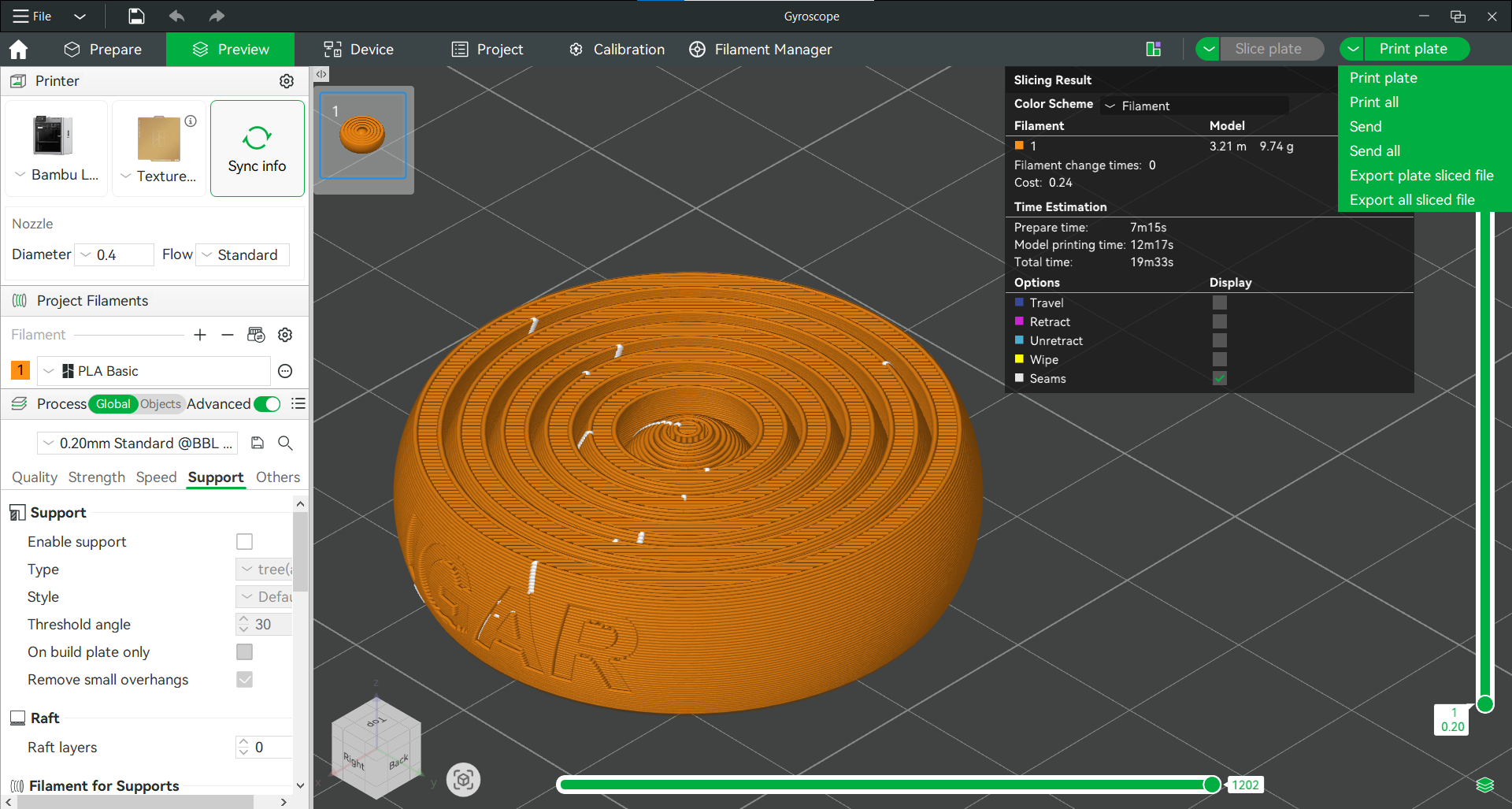
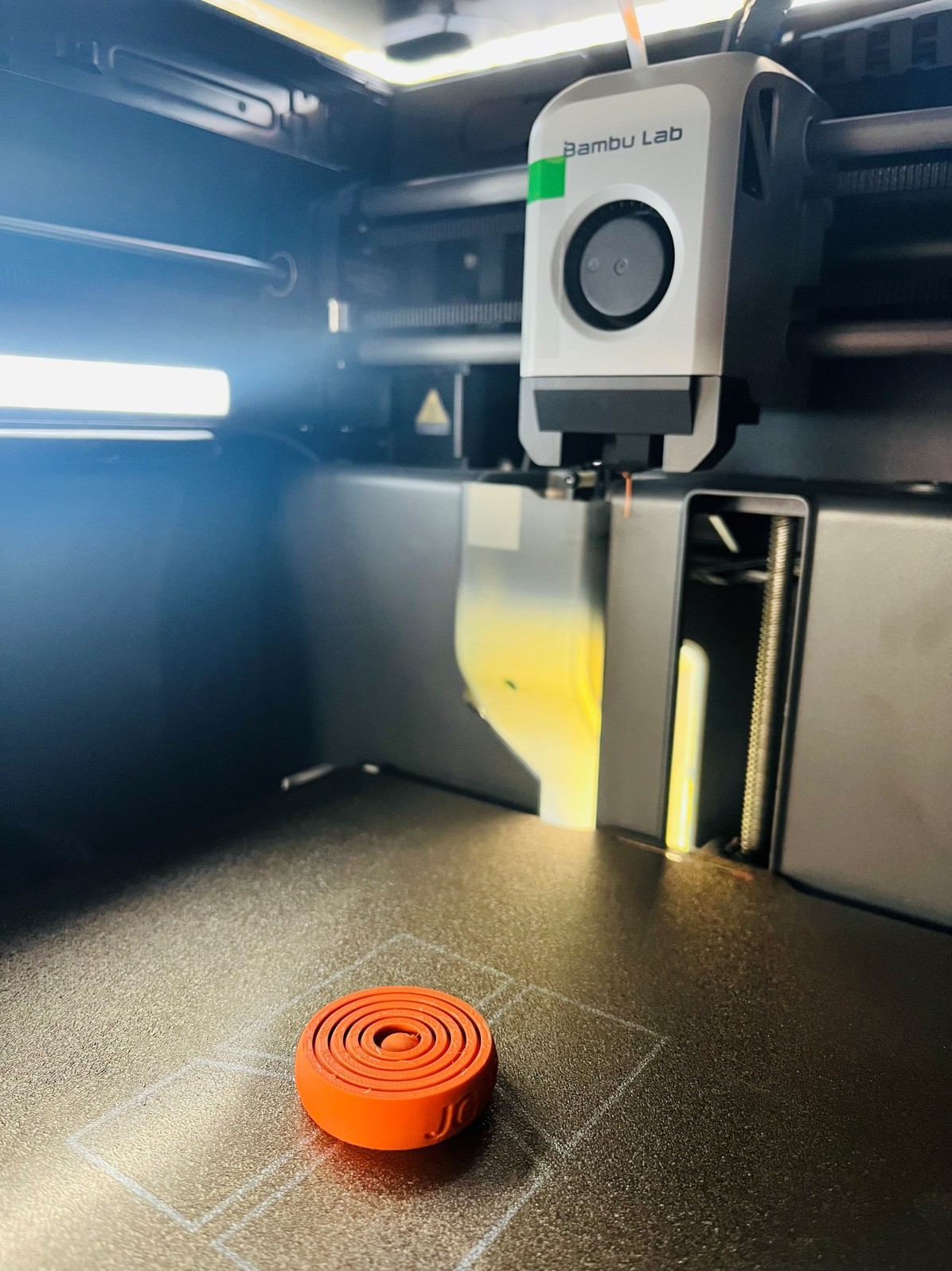
The model was sliced in Bambu Studio and printed on a Bambu Lab printer using PLA Basic filament. I used the 0.20mm Standard profile as the base configuration, with a 0.4mm nozzle. The only intentional change from the default settings was disabling supports. Supports were disabled, as the geometry was designed to be self-supporting and printable as a single assembly.
Printing Process
The gyroscope was printed using a Bambu Lab X1 Carbon printer available in the fab lab. The printing workflow consisted of the following steps:
- Power on the printer. The X1 Carbon automatically performs bed leveling and calibration routines, eliminating the need for manual setup.
- Load the filament. Orange Bambu PLA Basic filament was loaded through the AMS. Since the model was printed in a single color, the multicolor printing feature was not used.
- Send the print file. The sliced file generated in Bambu Studio was transferred to the printer.
- Start the print. Once the file was loaded and the automatic calibration was completed, the print job was initiated.
According to Bambu Studio, the estimated print time was 19 min 33 sec, with a material consumption of 9.74 g of filament.
Results
The gyroscope was successfully printed on the first attempt. All concentric rings were fully separated and moved freely directly from the build plate, requiring no post-processing or manual separation. The 0.80 mm clearance proved sufficient for reliable printing, and the embossed text on the outer ring was clear and legible.
Hero Shot 🥳
Finished print with all six concentric rings moving freely directly off the build plate.
3D scan an object
Preparation
The Object
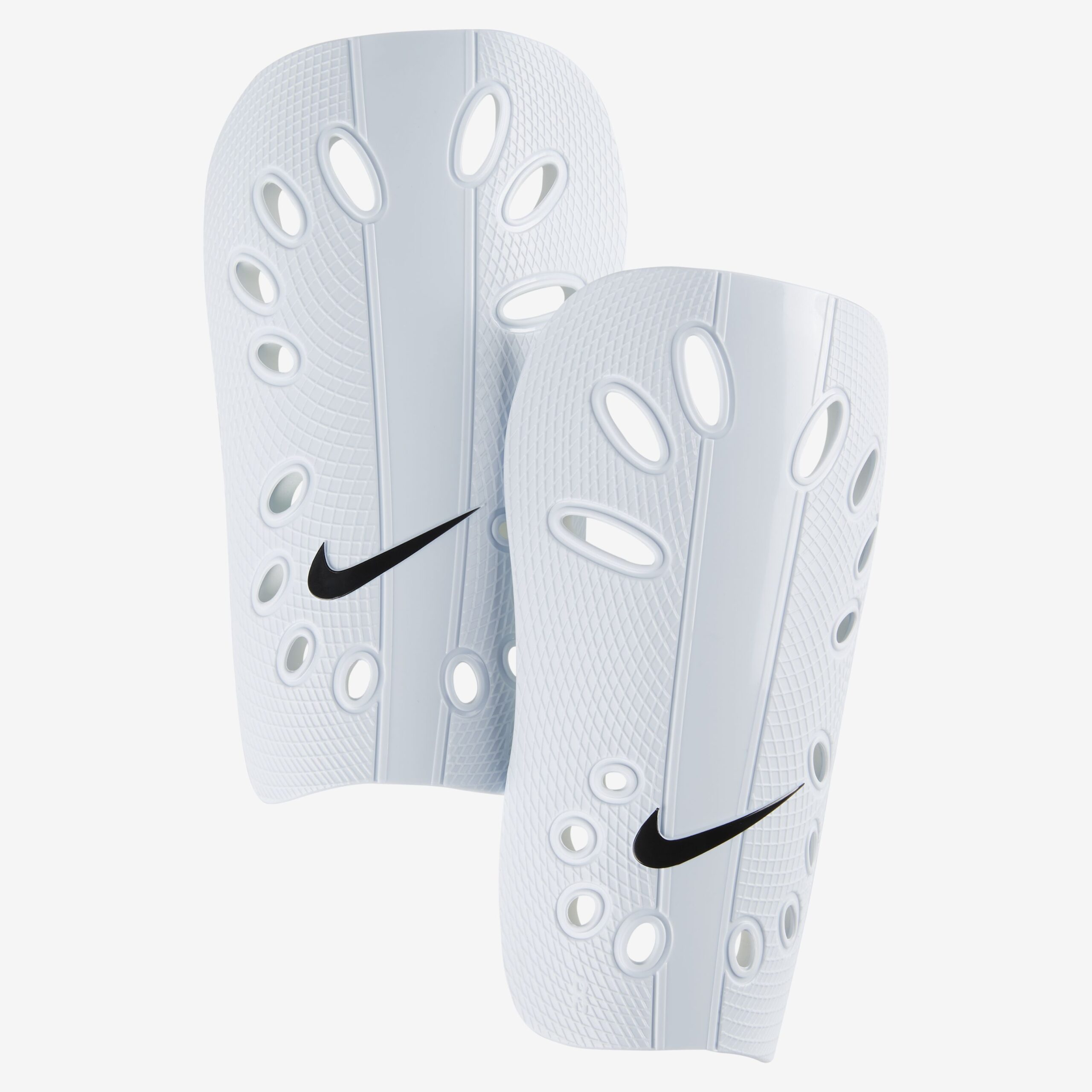
A few months ago, Fab Lab ESAN received an external service request that also gave us the perfect opportunity to put the recently arrived Creality CR-Scan Raptor to work for the first time. The object to scan was a shin guard — a compact piece with ventilation holes and a textured surface, which made it a good candidate to test the scanner's capability for capturing fine detail.
Calibration
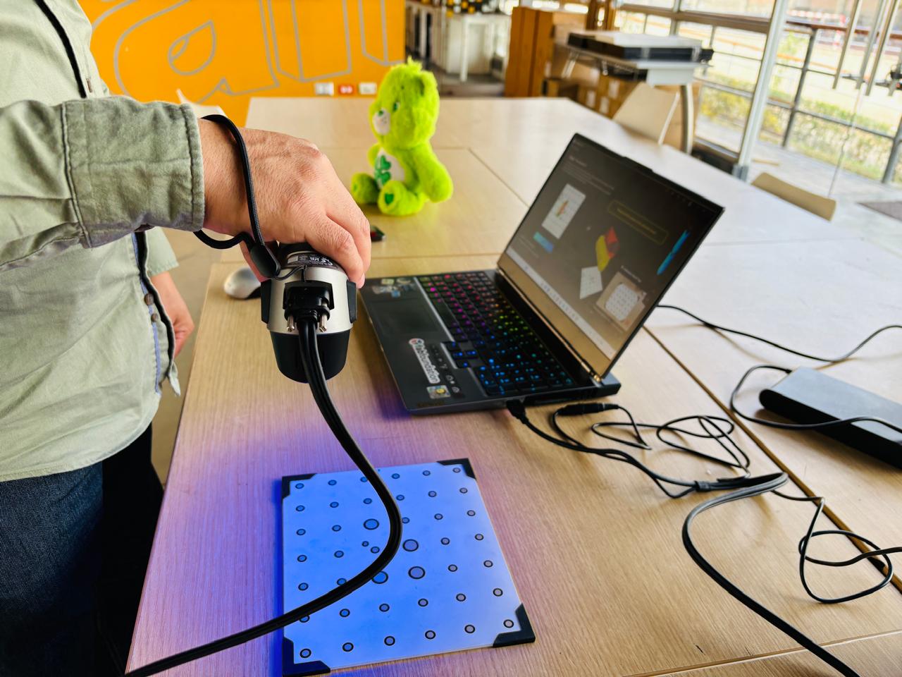
Before starting, the scanner was calibrated using its dedicated calibration board inside CrealityScan software. This step ensures the scanner is reading spatial data accurately before any capture begins.
Placing the Markers
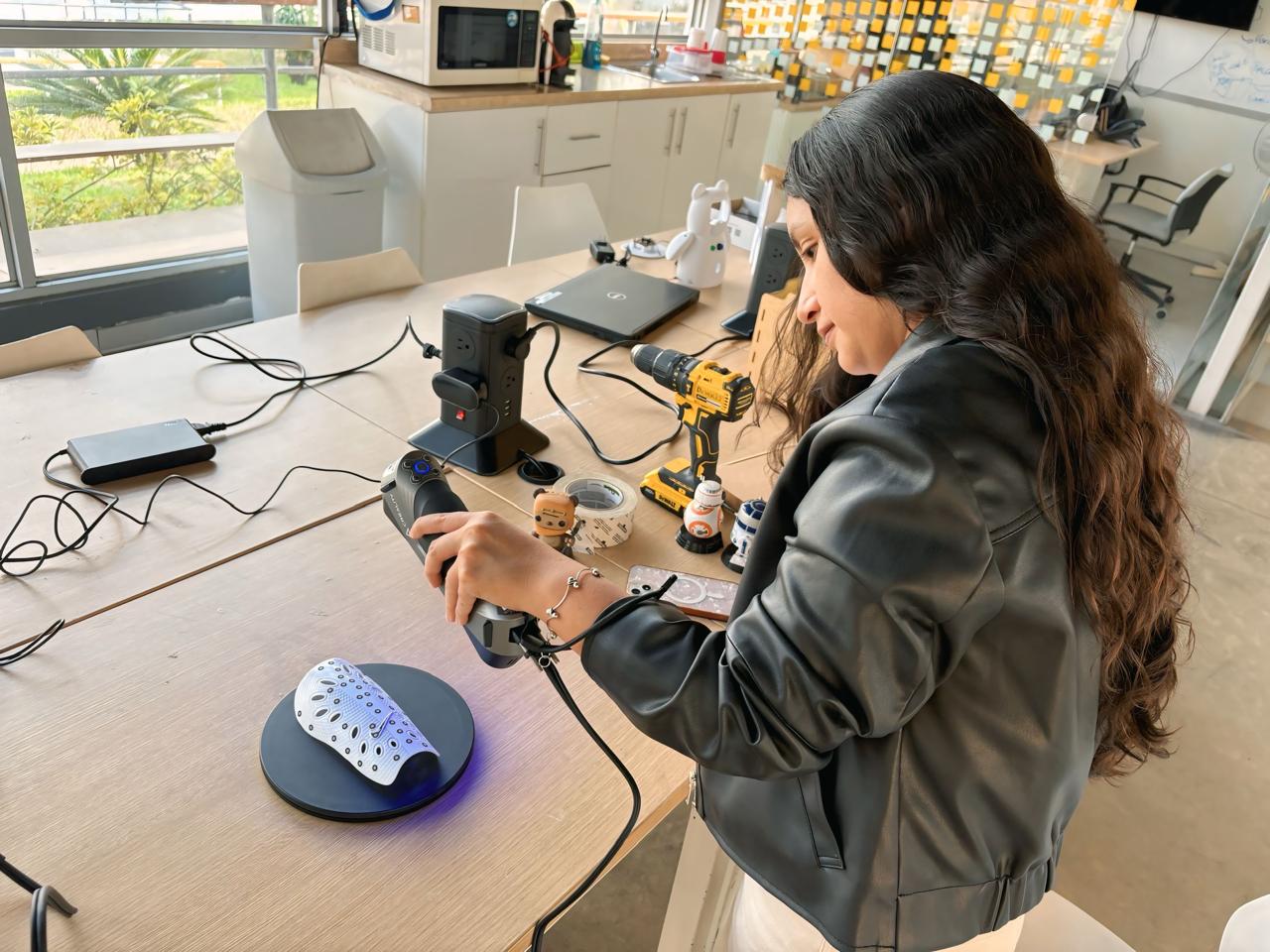
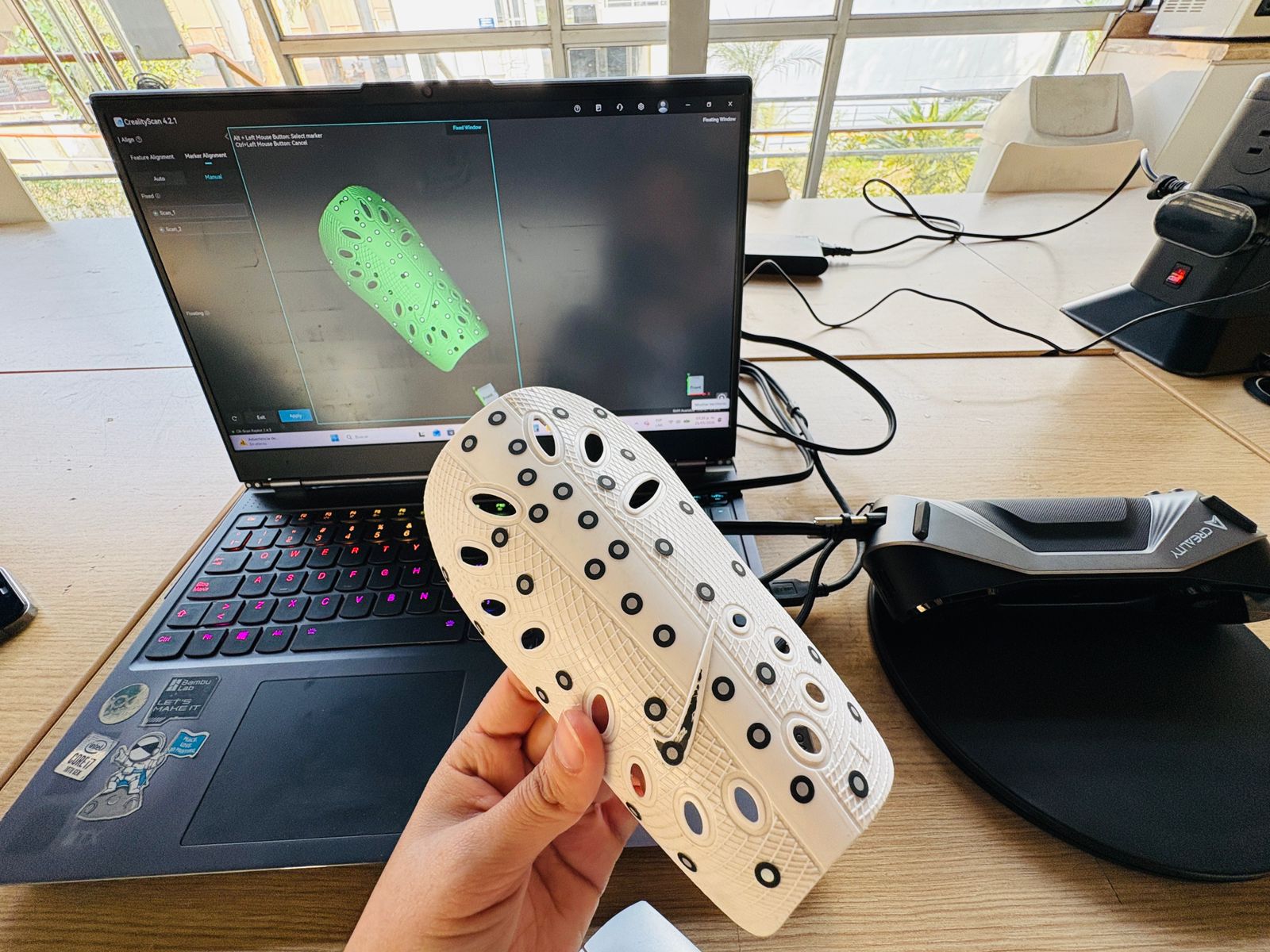
Once calibrated, reflective markers — small circular sticker dots — were applied directly onto the surface of the shin guard. These markers act as spatial reference points that the scanner tracks throughout the capture.
💡 An important detail: at least two markers need to overlap between the top and bottom areas of the object, so that both scan passes can be merged correctly during post-processing. With the markers in place, the scanning mode was set to Blue Laser Mode with Marker Tracking in CrealityScan.
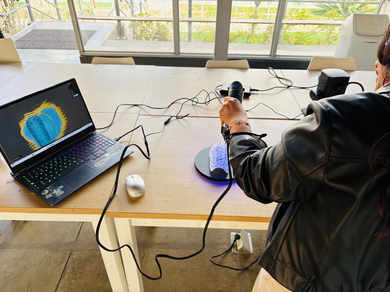
Scanning
First Pass
The first pass (Scan_1) covered the front and upper area of the shin guard. The scanner was moved slowly around the object while keeping a consistent distance, making sure every surface was covered. The progress is visible in real time on screen as the point cloud builds up.
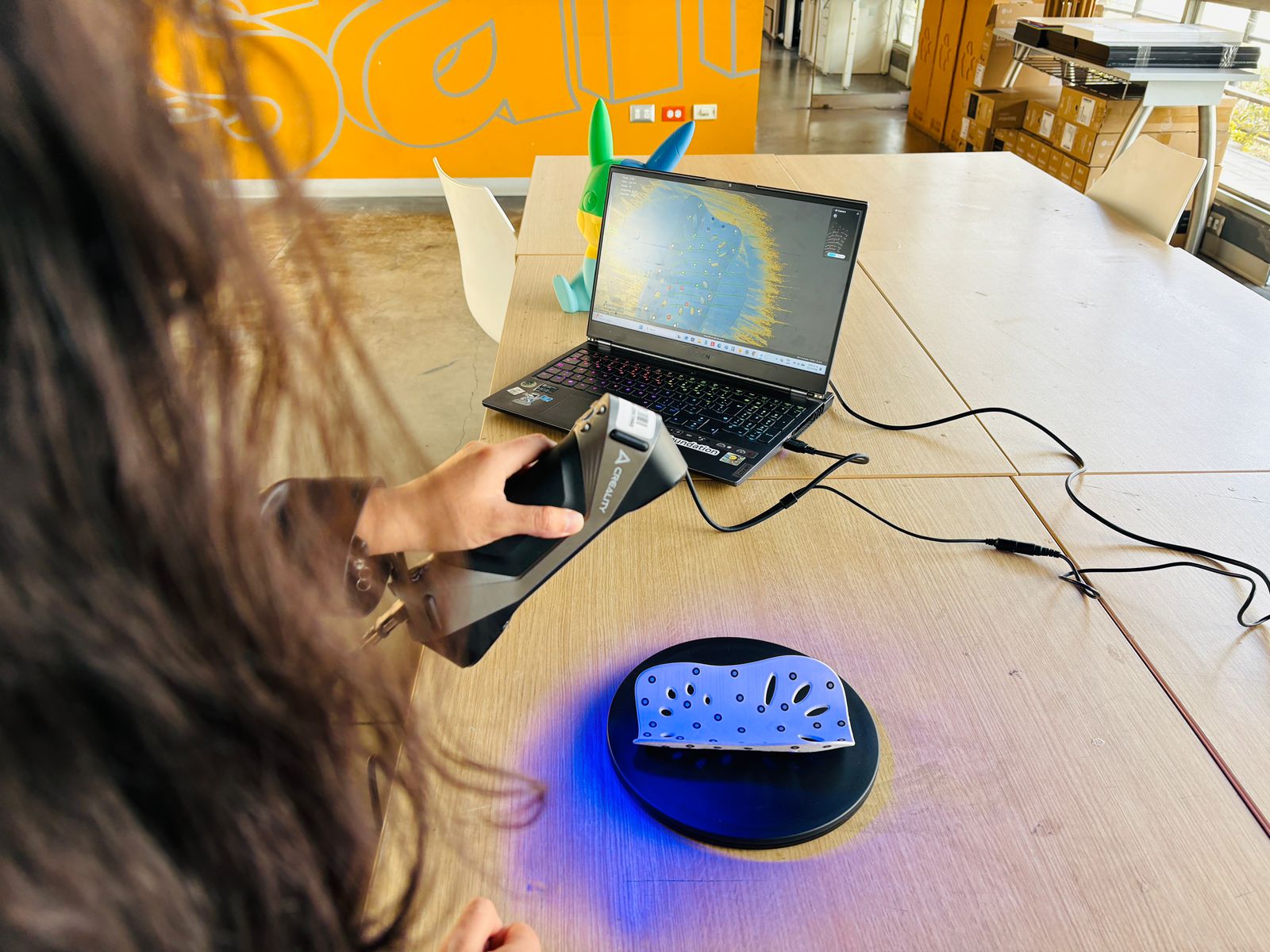
Second Pass
The second pass (Scan_2) captured the bottom and interior side of the shin guard, following the same approach — slow, consistent movement and full coverage of all surfaces.
💡 What to Keep in Mind: The shin guard was scanned lying flat. This worked fine, but it meant extra cleanup was needed in post-processing to remove the base surface. Scanning it upright from the start would have avoided that step — something to keep in mind for future scans.
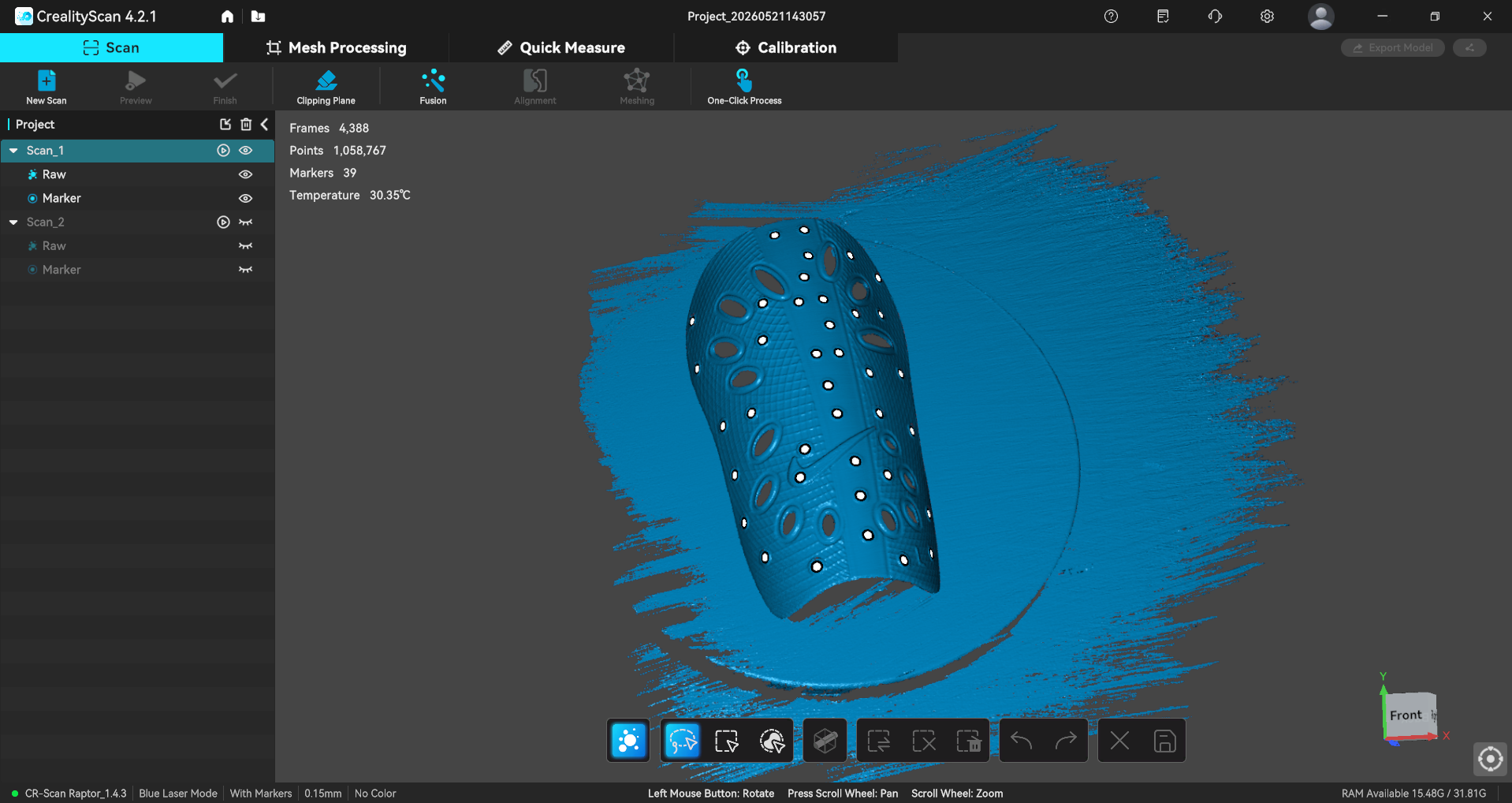
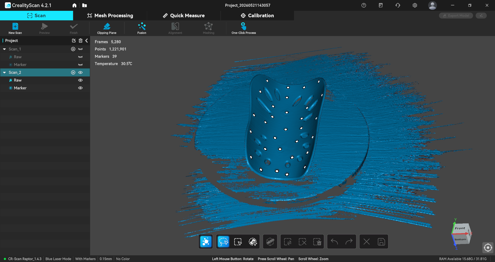
Scans captured in CrealityScan
Post - Processing
Cleaning the Point Clouds
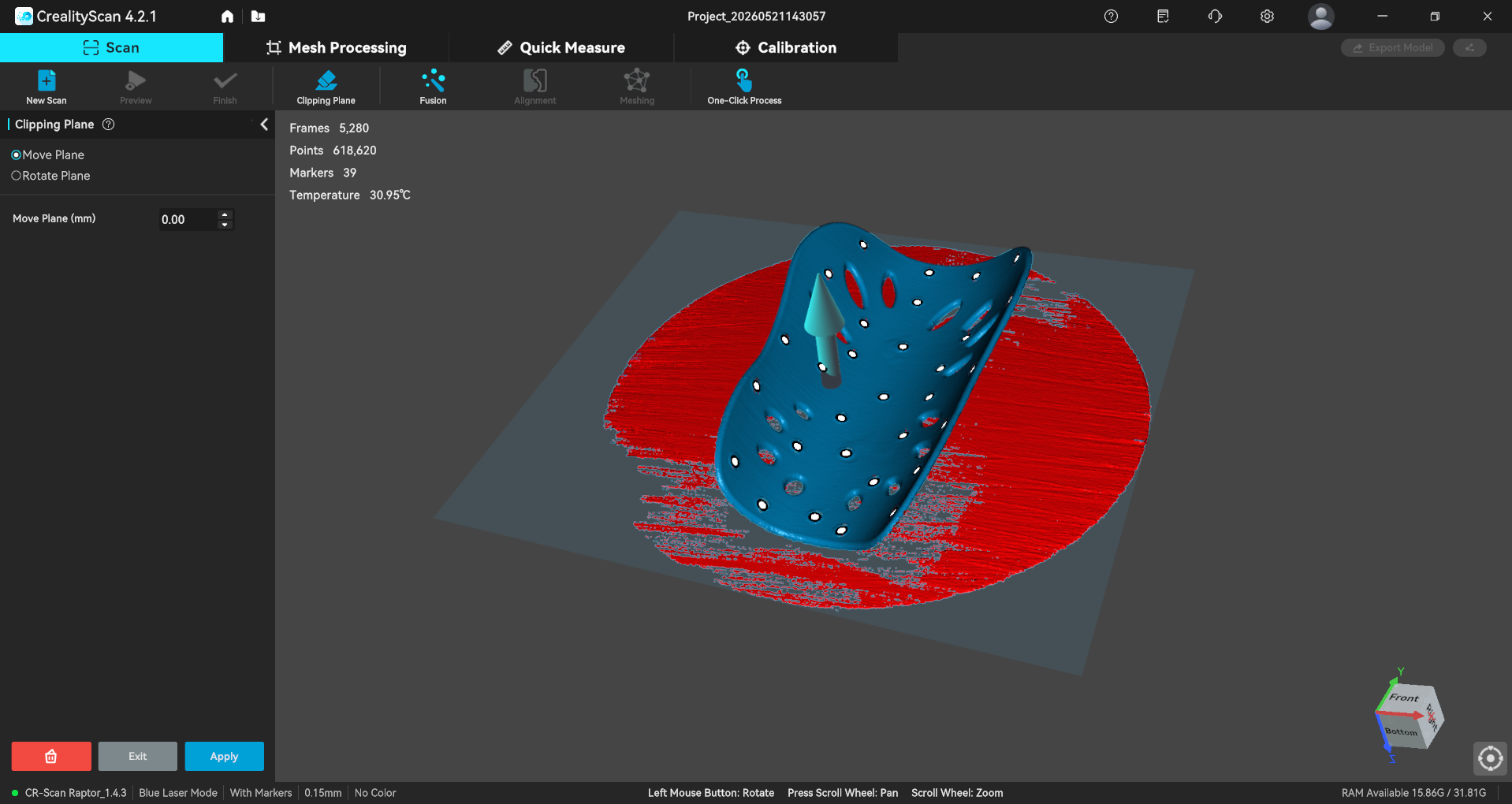
Once both scans were complete, the cleanup phase began. Using the Clipping Plane tool, everything that did not belong to the shin guard — the base surface and any scattered points — was removed from both point clouds.
Aligning the Scans
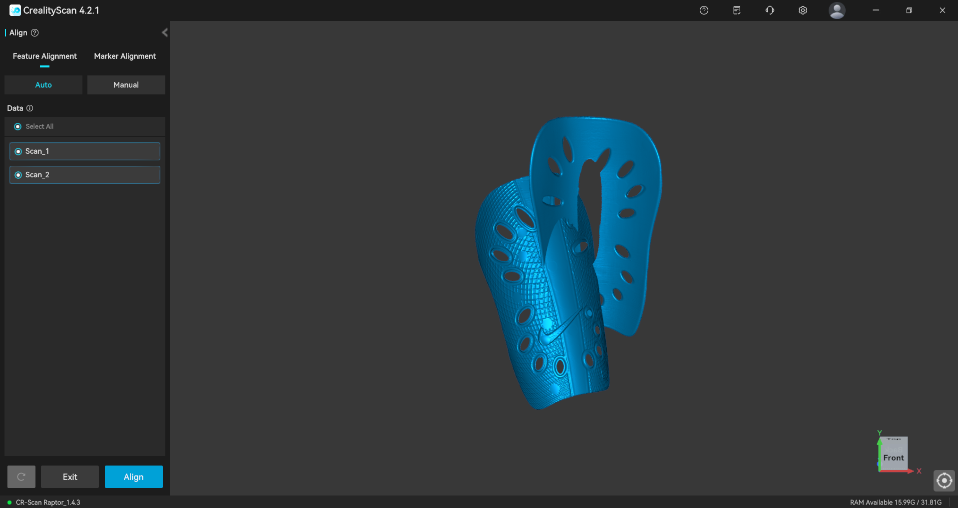
With the scan cleaned up, the next step was merging the two scans into a single model. Since each pass was captured from a different orientation, they needed to be aligned using the shared markers as reference. This was done through the Marker Alignment tool in Manual mode: corresponding marker points between Scan_1 and Scan_2 were matched one by one until the software could calculate the correct overlap. Once aligned, both scans were combined into a unified point cloud.
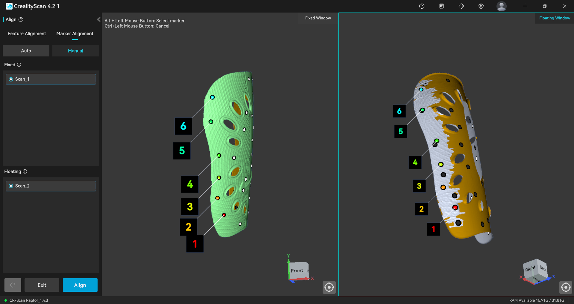
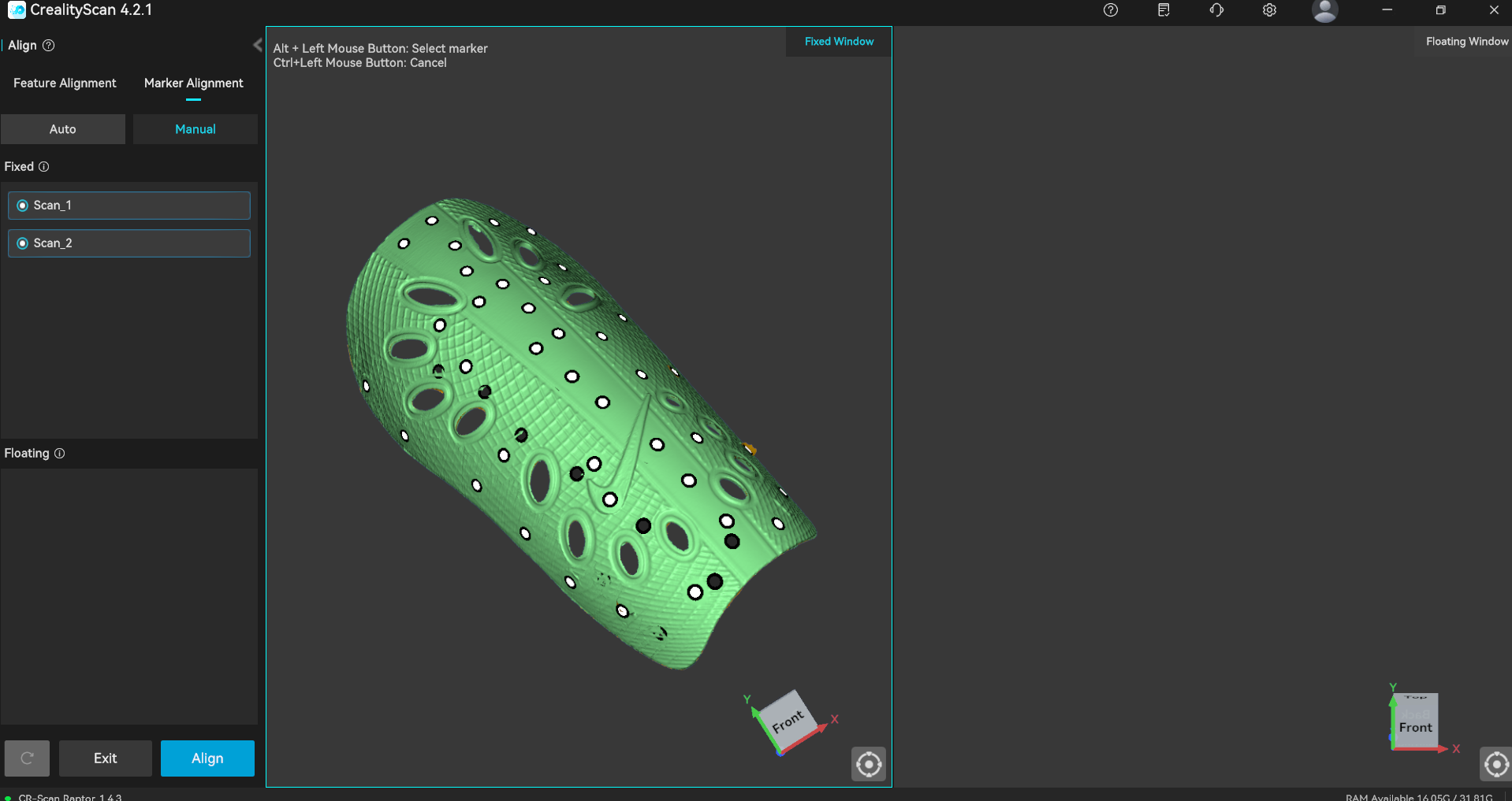
Manual marker alignment — matching corresponding points between Scan_1 and Scan_2
Generating the Mesh
The final step was generating the mesh at a resolution of 0.15mm, producing a model of 2,006,058 triangles. The result was exported as an STL file — and the scan was ready to be 3D printed.
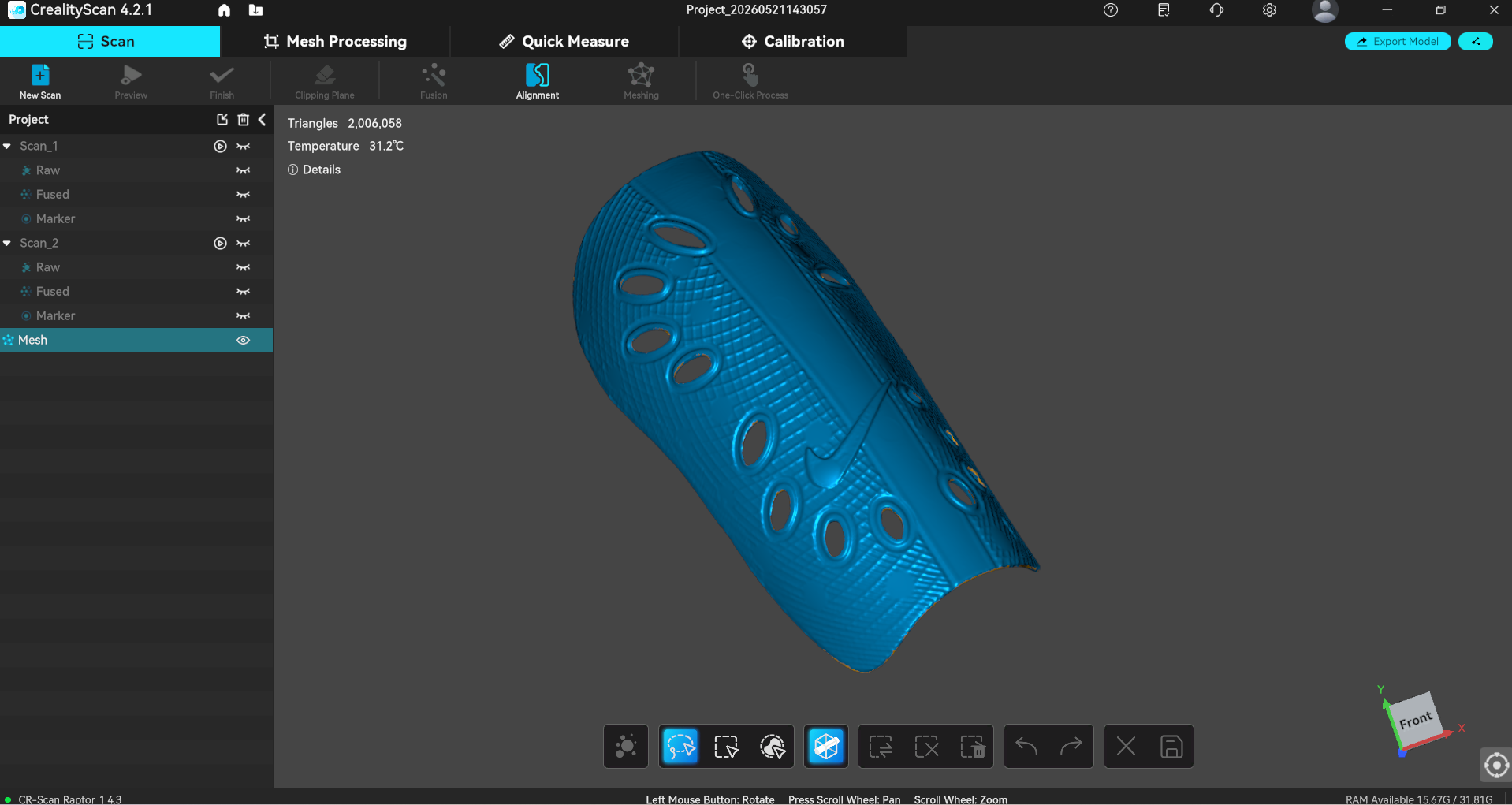
🥳 Hero Shot
From physical object to digital model — the shin guard fully scanned and ready to print.
Final Thought
As part of the 2025 cycle, my work on this week focused on the hands-on side of 3D printing: configuring the printers and running the test prints that would later serve as the basis for comparison. In 2026, I revisited this week to explore the results of those tests. I analyzed and compared the outcomes, drew conclusions from the observations, and also took on two new challenges: designing and printing the gyroscope — and learning to use the CR-Scan Raptor for the first time.