W16 | System Integration
📝 Assignment:
- Design and document the system integration for your final project
Final Project Overview 🐼
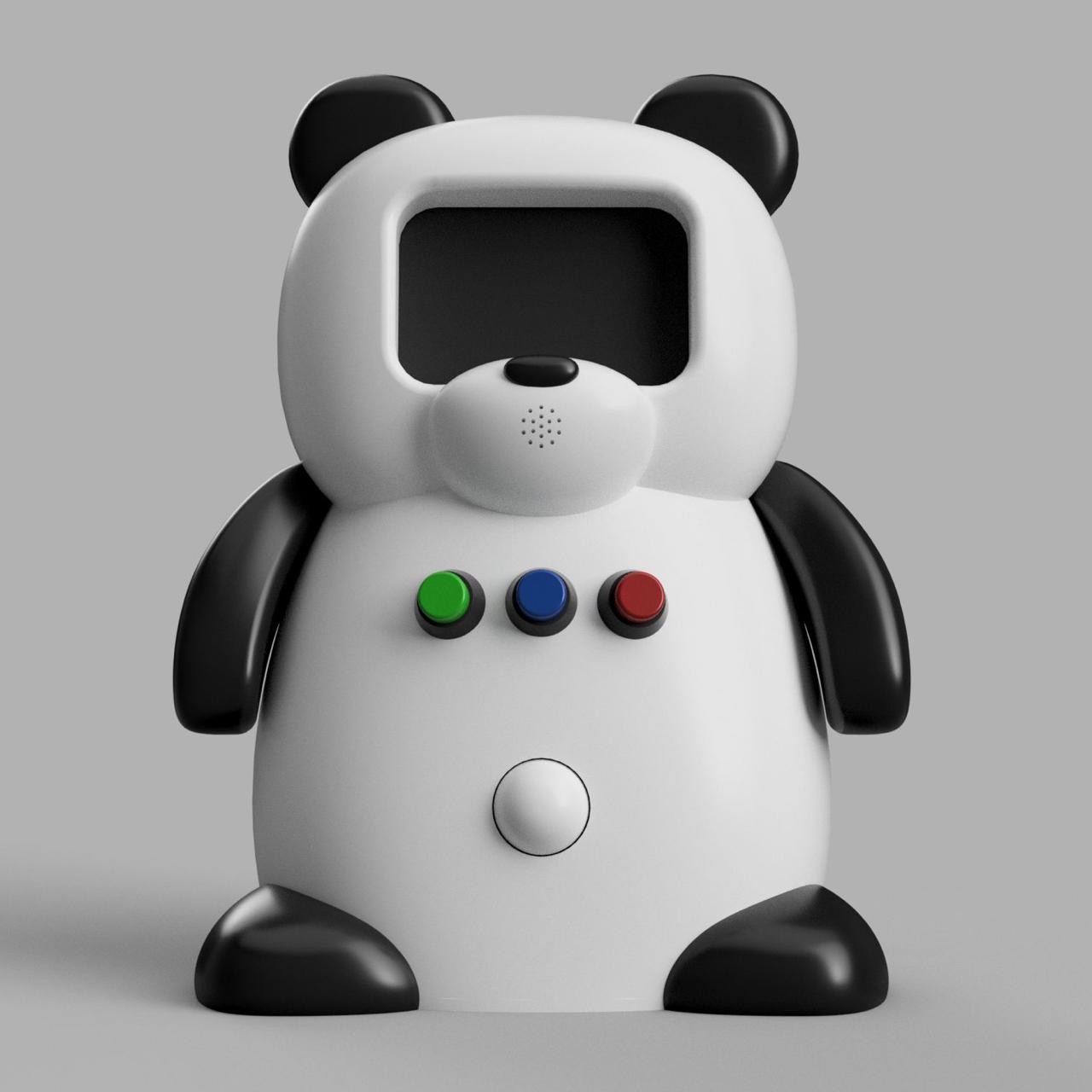
This project is a panda-shaped robot designed to support children during emotional regulation activities. The robot interacts with the child based on their emotional state — happy, sad, or angry — and responds with a specific combination of animations, movements, light, and sound for each one.
The system is made up of two physical parts that work together:
Both parts communicate over BLE (Bluetooth Low Energy), forming a complete wireless interactive system.
The robot integrates the following components:
| Component | Quantity | Function |
|---|---|---|
| XIAO ESP32S3 | 2 | Main microcontroller (robot) and accessory microcontroller |
| Nextion NX4832T035 | 1 | Display — shows animated expressions and instructions |
| Servomotors | 2 | Move the arms during each activity |
| NeoPixel LED Ring | 1 | Visual light feedback on the belly |
| Push Buttons | 3 | Child selects their emotional state |
| PIR Sensor | 1 | Detects presence and wakes the robot |
| MPU6050 | 1 | Accelerometer in the accessory — measures movement intensity |
| RGB LED SMD | 1 | Light feedback inside the bamboo accessory |
How the System Works
The robot is designed to support children during emotional regulation activities. When a child approaches, the PIR sensor detects their presence and the robot wakes up. It greets the child and asks how they are feeling through the display. The child responds by pressing one of the three push buttons — each one corresponding to a different emotional state.
Based on that selection, the robot guides the child through a specific interaction:
At any point in the interaction, if the robot determines the child needs more support than it can provide, it asks for an adult to step in.
System Components
| Input devices — what the robot receives: | ||
|---|---|---|
| Component | Connection | Purpose |
| Push Buttons (3) | Main board | Child selects emotional state — yellow, blue, red |
| PIR Sensor | Main board | Detects presence and wakes the robot |
| MPU6050 | Accessory board via BLE | Measures movement intensity of the bamboo |
| Output devices — what the robot does: | ||
|---|---|---|
| Component | Connection | Purpose |
| Nextion Display | Main board via UART | Shows animated expressions and instructions |
| Servomotors (2) | Main board | Move the arms according to each activity |
| NeoPixel LED Ring | Main board | Visual light feedback on the belly |
| RGB LED SMD | Accessory board | Light feedback inside the bamboo accessory |
Wireless communication
The accessory board reads the MPU6050 accelerometer and sends the acceleration data to the main board via BLE. The main board receives that data and determines the movement intensity level — low, medium, or high — and triggers the corresponding response.
Robot Flow
The flow below shows how the robot guides the child through each interaction — from the moment it wakes up to the farewell at the end. Each state specifies what happens on the display, the arms, the LED ring, and the buzzer, so every component has a role at every moment.
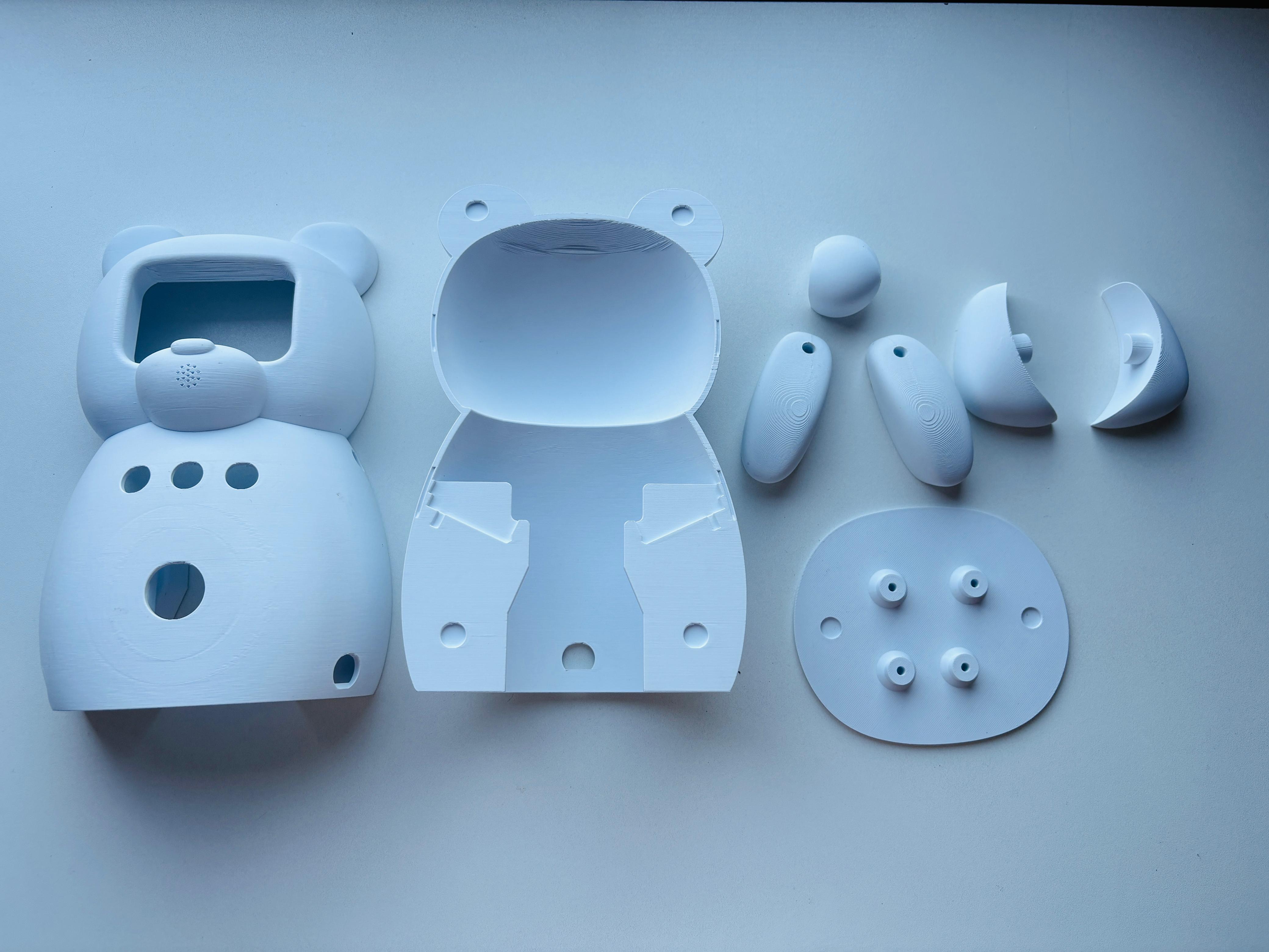
Physical Design and Packaging
The body of the robot was designed in Fusion 360. The starting point was two reference images generated by AI, which were used as canvas guides to model the panda shape using the Form tool — a sculpting feature that allows pushing and pulling surfaces freely, similar to working with clay. This made it possible to create the organic, rounded shape of the panda body without being limited to geometric forms. 🔗 Link to Week 2 — Computer Aided Design
▲ Head
Nextion Display + Buzzer
The display is mounted in the panda's face and framed by the head structure. The head includes a dedicated opening sized to fit the display, allowing it to sit flush with the surface. The buzzer is positioned behind the nose area, which includes small perforations that allow the sound to pass through while keeping the component hidden.
■ Body
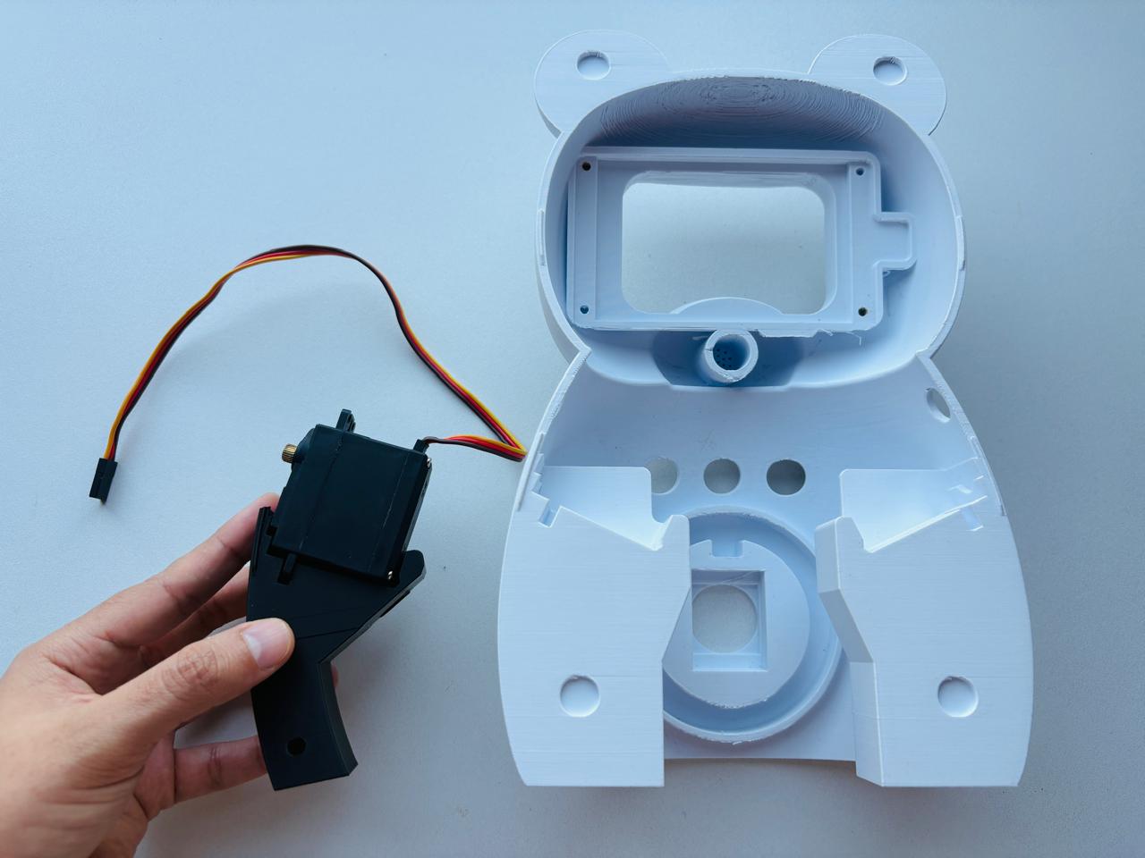
Servomotors
One servo is mounted on each side of the body in dedicated compartments inside the torso. The arms connect directly to the servo shafts, allowing controlled forward and upward movement.
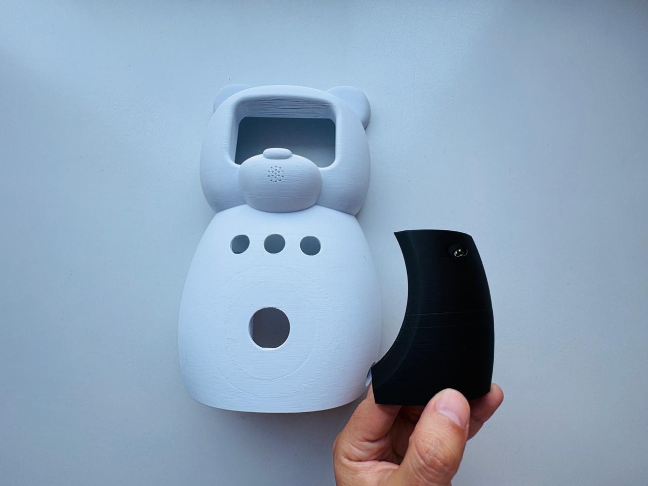
Push Buttons
Three buttons are positioned on the chest, making them easy for a child to reach and press. Shorter buttons were selected to reduce the space required inside the body.
PIR Sensor
Located on the lower front of the body and positioned to detect the presence of a child standing in front of the robot.
NeoPixel LED Ring
Mounted inside the belly behind a section of the wall designed with reduced thickness. This allows the light to diffuse through the material, creating a soft glow effect rather than exposing the LEDs directly.
▼ Base
Main Board
Mounted inside the base of the robot in a dedicated compartment designed for the electronics. This location helps organize the wiring and keeps the center of gravity lower.
Iteration Process
Each part was printed and tested separately before printing a complete version:
▲ Head
Printed first to check the display position and fit, verifying that the cutout aligned correctly and that the display sat flush with the surface.
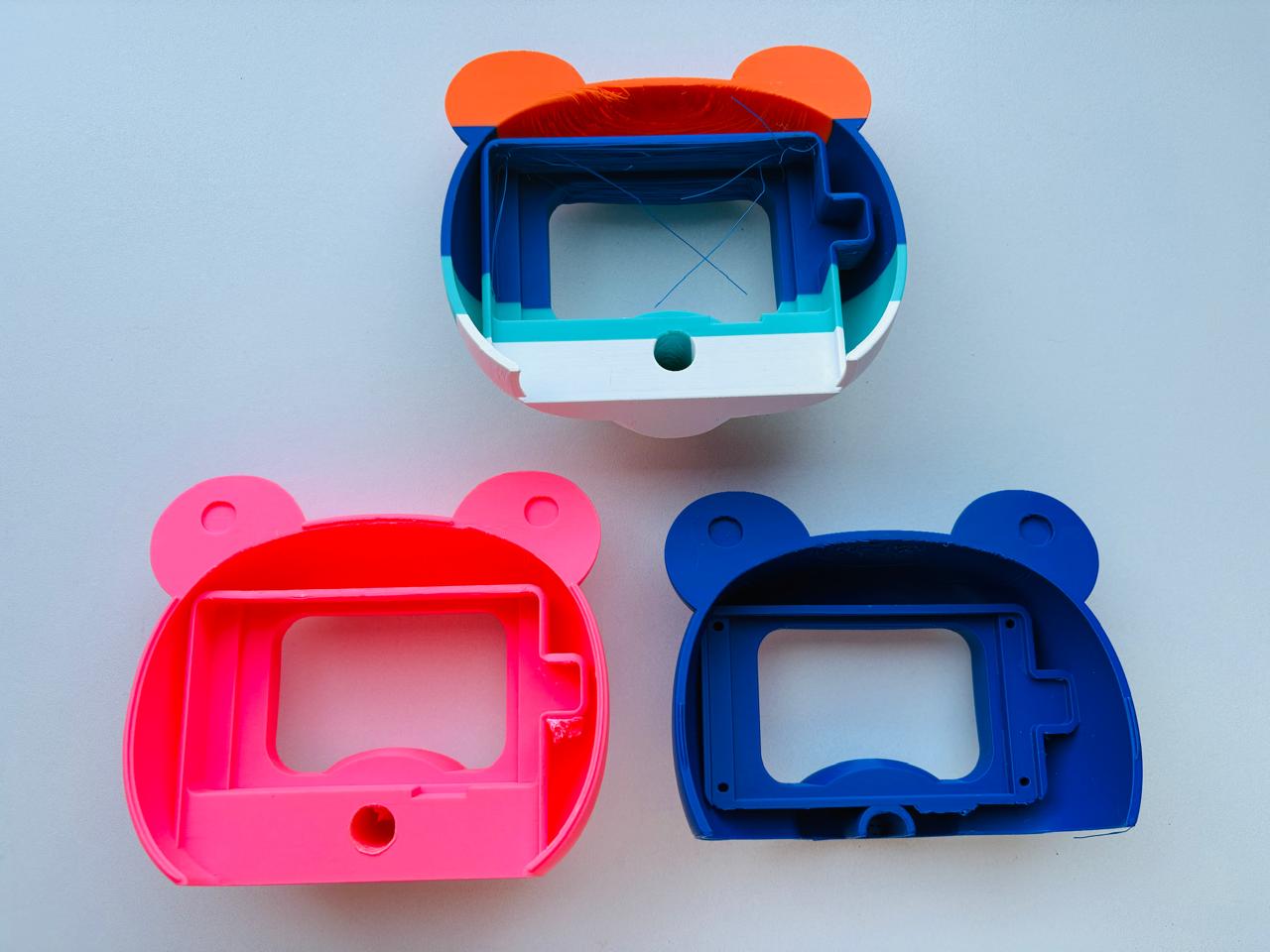
■ Body
Printed to verify components placement, internal spacing, and how all the components would fit together.
The first complete prototype revealed several problems that led to a redesign:
Cables were disorganized
There was no clear path for the wiring, making the interior difficult to organize and assemble. In the redesign, dedicated cable-routing channels were added to guide the wiring through the body, and cable lengths were reduced during assembly to create a cleaner and more manageable layout.
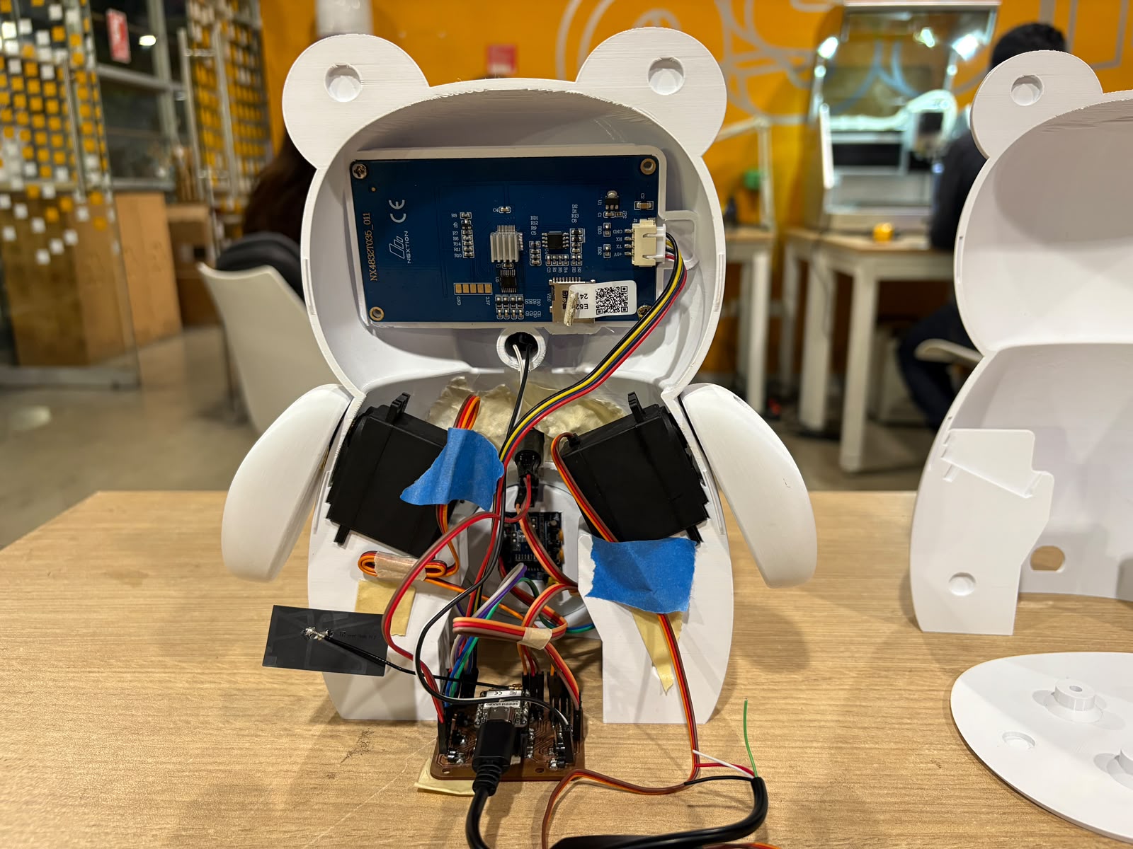
Components were too close together
The servomotor brackets were the biggest challenge, as their base occupied too much space inside the torso. The brackets were redesigned to reduce their footprint, freeing up room for cables and the other components.
Connection system needed rethinking
The original design used magnets to join the pieces, but after testing the robot would have been too heavy. The solution was to switch to threaded inserts and screws — metal inserts are embedded into the printed parts and screws go through them, creating a strong and clean connection. These were designed to be as hidden as possible so they do not affect the final appearance.
Bamboo Accessory
The bamboo accessory is designed to be squeezable, and is currently still in testing. The design uses two materials printed in a single process on the Bambu Lab H2D: a transparent PETG inner capsule so the RGB LED light can pass through, and a transparent TPU outer layer that gives the accessory its soft, squeezable feel. The infill pattern is being tested and adjusted to find the right balance between structure and softness.
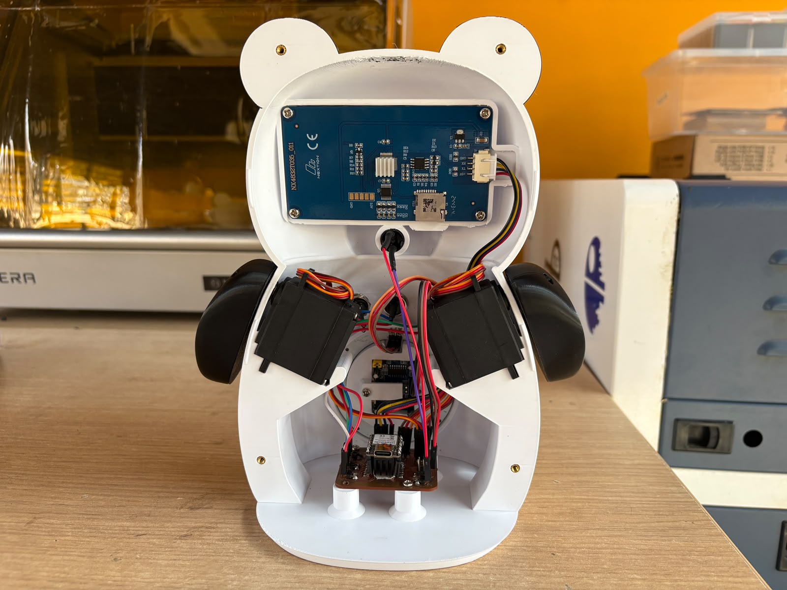
Current State
The robot is at an advanced stage of integration. The physical body is fully assembled in its final version — printed in multiple colors using the multi-filament capabilities of the Bambu Lab printer, and with all components mounted in their dedicated spaces. The internal wiring is organized, cable lengths have been reduced by soldering them directly where needed, and each component has a clearly defined place inside the body.
| Component | Status | Week documented |
|---|---|---|
| Nextion Display | ✅ Working — animations running | Output Devices |
| NeoPixel LED Ring | ✅ Working — color control tested | Output Devices |
| MPU6050 accelerometer | ✅ Working — three levels detected | Input Devices |
| BLE communication | ✅ Working — both boards communicating | Networking |
| Push Buttons | ✅ Working | Input Devices |
| Servomotors | 🔄 Integrated — pending full programming | — |
| PIR Sensor | 🔄 Integrated — pending full programming | — |
| Bamboo accessory | 🔄 In progress — PETG + TPU tests ongoing | — |
| Screen animations | ✅ 12 screens designed in Procreate | Computer-Aided Design |
| Robot body — 3D printed parts | ✅ Printed and assembled | Final Project |
| Full system flow | 🔄 Pending final integration of all components | — |
Final Thought
As part of the 2026 cycle, I continued developing the robot's mechanical design, refining the enclosure and component integration through several iterations. The iteration process was an important part of the development. Printing, assembling, and testing physical prototypes made it possible to identify issues that were difficult to anticipate in the CAD model and refine the design accordingly. It also helped me validate how the different components fit and work together in the final design.