
W10 | Output Devices
📝 Group Assignment:
- Measure the power consumption of an output device.
- Document your work on the group work page and reflect on your individual page what you learned.
What We Did
For the group assignment, we measured the power consumption of a stepper motor under two conditions: stopped and moving. The goal was to understand the difference in energy demand depending on the device's state, using the formula:
We assembled a circuit using an Arduino UNO, a DRV8825 stepper motor driver, and a NEMA 17 stepper motor. The power was supplied through a GW INSTEK GPD-3303D laboratory power supply, which allowed us to read the voltage and current directly. The voltage was set to 11.9 V in both tests. The current was read from the supply display for each condition, and the power was calculated from those values.
| State | Voltage (V) | Current (mA) | Power (W) |
|---|---|---|---|
| Motor stopped | 11.9 | 0.23 | 2.74 |
| Motor moving | 11.9 | 0.37 | 4.40 |
The results show that the motor draws more current — and therefore more power — when it is actively rotating. Even when stopped, the motor consumes power because the driver keeps current flowing through the coils to hold its position.
🧠 What I learned
This activity gave me the opportunity to apply the formula P = V × I directly on a real device, measuring the values from the power supply. The difference between the two measurements — 2.74 W and 4.40 W — reflected this directly. When the motor rotates, it has to overcome inertia and generate mechanical torque — this demands more current from the coils. Since power depends directly on current, higher current means higher power consumption. When stopped, the driver only maintains enough current to hold the position. In short: moving costs more energy than staying still, and this applies to any electric motor.
📝 Individual Assignment:
- Add an output device to a microcontroller board you've designed and program it to do something.
What is an Output Device?
An output device is any component that allows a microcontroller to send information back to the world. While an input device brings data in, an output device communicates something out — as light, movement, sound, or in this case, images on a screen.
Some common examples are:
- An LED — signals a state with light
- A motor — produces physical movement
- A speaker — generates sound
- A screen — displays visual information
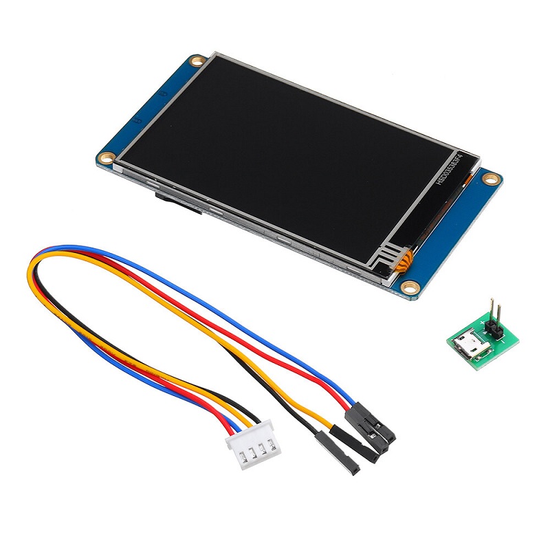
🔎 In this week's assignment, the output device used is a Nextion NX4832T035 display. In the context of the robot, this screen is the main way it communicates with the child — it displays animations that correspond to the different activities the robot performs. This week's work focuses on getting the display working and understanding how to control it from the microcontroller, using an eye animation as the first proof of concept.
Why This Output Device
The robot needs a way to communicate visually with the child, and expressive animations make the interaction feel more natural and engaging. The Nextion NX4832T035 was chosen because it handles the graphics internally, allowing the microcontroller to control the screen using serial commands. Since the display does not support video playback, the animation is created by showing multiple image frames quickly to simulate movement.
The Board
For this week, the board used is the Final Project Board fabricated in Week 8. In that week, the board was already tested with an output device — an LED ring — which can be reviewed in the corresponding documentation. This week, the same board is used to connect and control the Nextion display.
Nextion NX4832T035
The Nextion NX4832T035 is a 3.5-inch smart display with its own processor and built-in flash memory. Unlike a regular screen, it stores and manages the graphics internally, so the microcontroller only needs to send commands telling the display what to show.
Communication with the microcontroller is done through UART, a simple serial communication protocol that uses two main pins:
- TX (Transmit) — sends data to the display
- RX (Receive) — receives data from the display back to the microcontroller
Tools Used
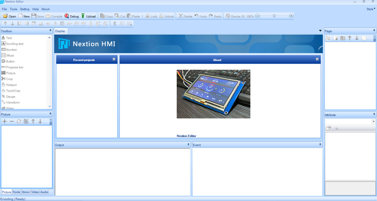
Nextion Editor — the software used to design the screen interface. It allows importing images, arranging them into pages, and programming the animation logic. The final design is compiled into a .tft file and loaded onto the display via a microSD card.
Arduino IDE — used to program the XIAO ESP32S3 on the main board. From here, commands are sent through the serial port to control what the Nextion displays.
Programming the Display
Since the Nextion does not support video files, the animation is built by cycling through a sequence of images rapidly — similar to how a GIF works. Here is the complete workflow:
Step 1 — Design the frames in Procreate
Each frame of the animation was drawn individually in Procreate. Once finished, the images were exported and resized to exactly 480 × 320 px — the resolution of the Nextion NX4832T035. This step is important because the images must match the screen size exactly, otherwise they will not display correctly.
Step 2 — Create a new project in Nextion Editor
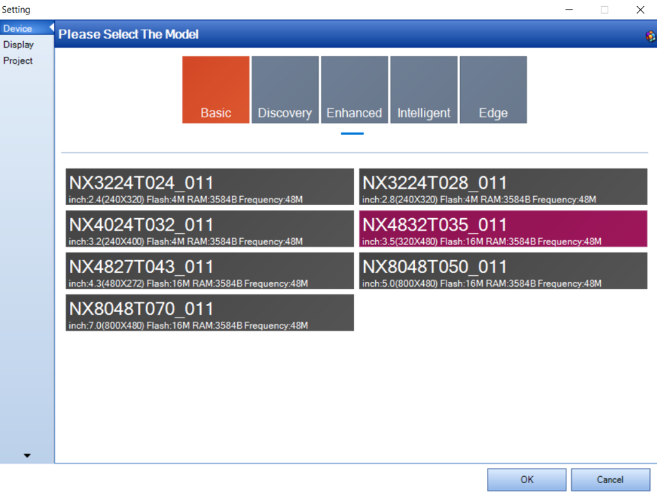
Open Nextion Editor and create a new project. Make sure to select the correct device model — in this case the NX4832T035 — so the canvas matches the screen dimensions.
Step 3 — Import the images
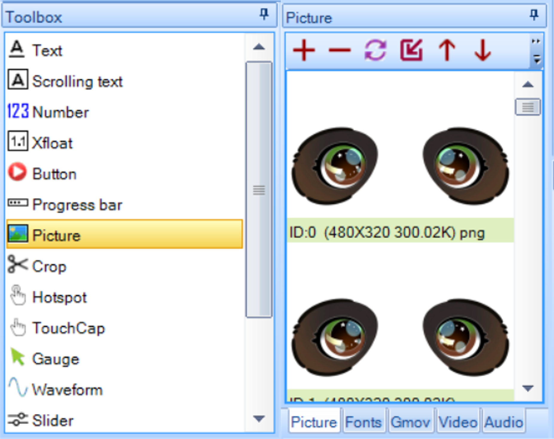
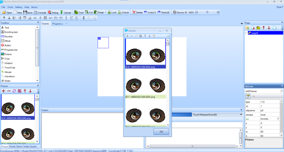
In the Picture panel at the bottom left, click the + button to add the images. All 16 frames were imported in order — Nextion assigns them index numbers automatically starting from 0.
Step 4 — Add the Picture component
On the main canvas (page0), add a Picture component from the Toolbox. Resize it to cover the full screen (480 × 320) and position it at x:0, y:0. This component — named p0 — is what will display each frame of the animation.
Step 5 — Add a Timer and a Variable
Two components are needed to make the animation run:
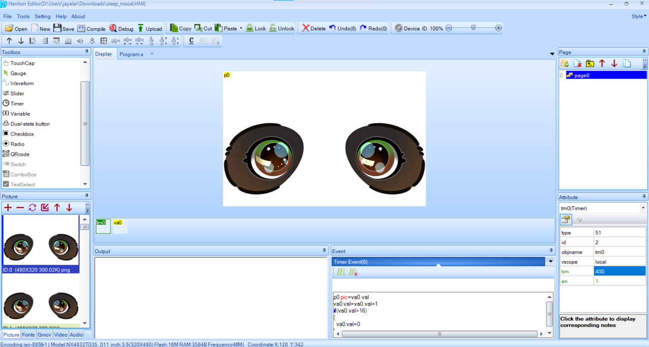
- Timer (tm0) — executes code automatically at a set interval. The
timattribute was set to 300ms andento 1 (enabled) - Variable (va0) — stores the current frame index as a number, starting at 0
Step 6 — Write the animation code in the Timer
Click on the Timer and go to the Timer Event. Add the following code:
p0.pic=va0.val
va0.val=va0.val+1
if(va0.val>16)
{
  va0.val=0
}
Step 7 — Compile, Debug and verify
Click Compile to build the project, then click Debug to open the simulator and preview the animation directly in Nextion Editor. If the frames cycle correctly, the design is ready to upload to the screen.
How the Code Works
1. For this test, most of the logic runs directly on the Nextion display. The animation is handled by a Timer inside Nextion Editor with the following code:
p0.pic=va0.val
va0.val=va0.val+1
if(va0.val>16)
{
  va0.val=0
}
p0.pic=va0.val— shows the image that matches the current counter numberva0.val=va0.val+1— moves to the next frame by adding 1 to the counterif(va0.val>16)— checks if it has reached the last frameva0.val=0— if so, resets the counter to 0 and starts the loop again
2. On the Arduino side, the XIAO ESP32S3 communicates with the Nextion through pins D6 (TX) and D7 (RX):
Serial1.begin(9600, SERIAL_8N1, D7, D6);
3. Commands are sent with three 0xFF bytes at the end — that is how Nextion knows a command is complete:
Serial1.print("page 1");
Serial1.write(0xff);
Serial1.write(0xff);
Serial1.write(0xff);
4. For this test the screen runs the animation autonomously. The Arduino code will send commands to control the display once the full robot logic is integrated.
Uploading the design to the screen
- Go to File → TFT file output in Nextion Editor and save the generated file
- Copy it to the root of a microSD card formatted in FAT32
- Insert the microSD into the display before powering it on
- Power on — the screen loads the file automatically
- When it shows "Update Successful", power off, remove the SD and power on again
Connecting the Display
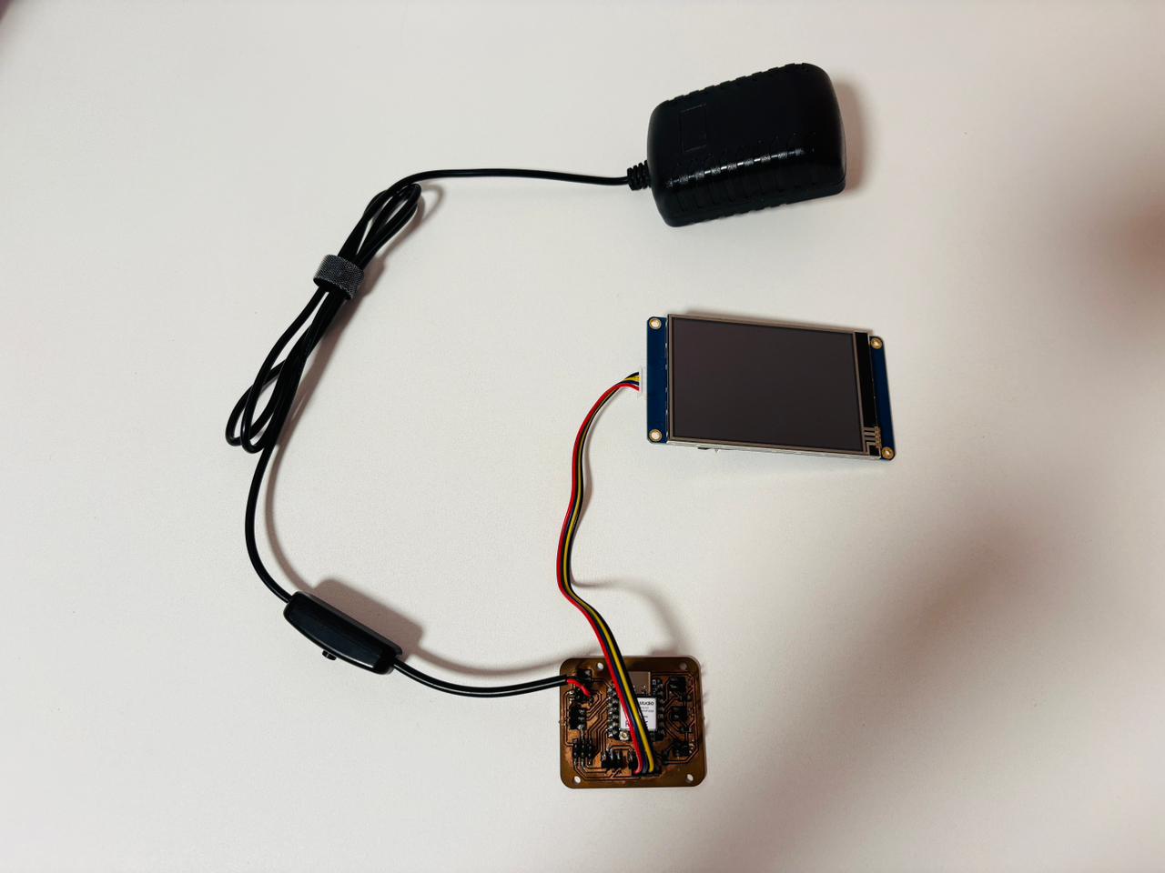
The Nextion display connects directly to the main board using four wires — VCC, GND, TX, and RX. The main board has dedicated pin headers for all four connections.
| Nextion Pin | Connection |
|---|---|
| VCC | 5V (external power supply) |
| GND | GND |
| TX | RX on XIAO ESP32S3 |
| RX | TX on XIAO ESP32S3 |
Since the Nextion requires 5V to operate, a 5V power adapter connects to the main board through its power pin headers. From there, the board distributes the power to the display.
⚠️ Problems & How I Fixed Them
Problem 1 — Parse error in Nextion Editor
While writing the animation code in Nextion Editor, this error appeared: "Parse: Assignment operation failed". The issue was the order of operations — p0.pic=va0.val was placed before the counter update, so the image was being assigned before the value was validated.
✅ Fix
Reorder the code so the counter updates and resets first, then the image is assigned. The correct order is: increment → check limit → assign to picture.
Problem 2 — Screen stuck on "Update Successful"
After the file loaded correctly, the screen stayed on the update message and did not show the animation.
✅ Fix
Turn off the screen, remove the microSD, and turn it back on. Nextion only reads the SD card at startup to check for updates — if the SD stays inserted, it keeps waiting. Without the SD, it boots normally and runs the loaded design.
Hero Shot
🎉 The Nextion display successfully shows a looping eye animation that gives the robot a visual identity. The animation runs smoothly and the communication between the XIAO ESP32S3 and the screen works reliably through UART.
Nextion display showing animated eyes
Final Thought
As part of the 2026 cycle, in this assignment, I learned how to connect an output device — the Nextion NX4832T035 — to a microcontroller and control it through UART serial communication. I understood that the TX (transmit) and RX (receive) pins are used to exchange data between the display and the microcontroller, allowing commands to be sent to control what appears on the screen. I also learned that some output devices include their own processor and memory, allowing them to handle graphics and animations independently from the microcontroller. Another important lesson was finding a workaround for the display’s lack of video support by creating animations from a sequence of image frames instead.