Requirements
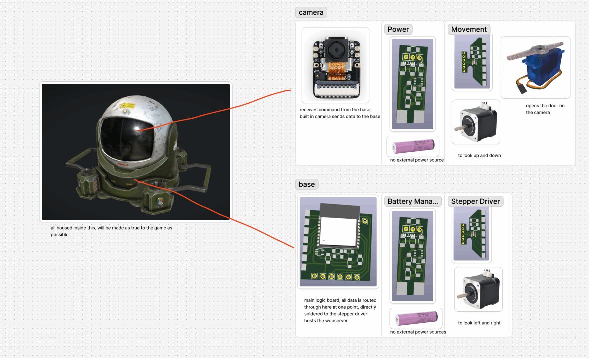
My final project will be a rotatable pan-tilt turret. I will attempt to make it as similar to what it is based on, a gadget from a game called "Rainbow Six Siege". in the game, the "operators" can pull out their phone, and then go on camera to look around. While on their phone, they can move this camera to look in any direction horizontally and around 120 degrees vertically. Additionally, this camera specifically can open the black panel on the front, in order to give the camera an undistorted view. If you go to the 3d model above, and look near the bottom of its box, and change the static pose to moving pose, you can see exactly how it moves in game, and how I want it to move. I also want to keep this working after fab, and put it in my room somewhere, so it has to work well enough to make it out of fab academy alive.
I used this as a reference, its liscense does allow me to modify it with attribute, so my design was based on the one above, which can be found here
Sketch
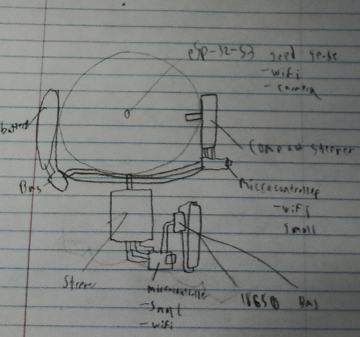 This sketch outlines the major electronic components of the camera. In order for it to be able to rotate infinitely along its base, it needs to have no wires connecting the base and the head, or a slip ring. When I was researching it, while a slipring seemed interesting, I have more experience with batteries and decided to go the disconnected route. It would probably be more reliable or at least easy to replace an old battery than a broken slip ring. I also have some experience with stepper motors when experimenting with making a gantry for them, so I decided to go with a thin stepper for the one connecting the head to the rotatable base, and a larger one connecting the rotatable base to the unmoving base. All the logic will be run through either a Seeed xiao esp32-s3 sense for the camera, or my own custom esp32-c3 board. I plan on redesigning the board for the fourth time specifically for this. This means I will target compactness, removing the usb-c port i added, and breaking out around 8 pins total for the board. 2 usb datalines that will be soldered directly on, 2 will be power and ground, and 4 will be for the stepper.
3D design
First pass
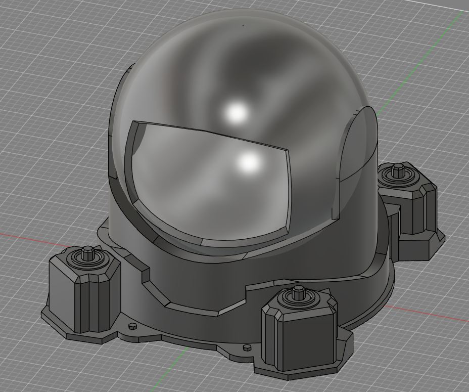
As part of cad week. I designed the 3d portion of my final project. To give a basic overview, I used one sketch per part, with 3 separate parts that I called the unmoving base, the moving base, and the head. both base pieces were not that complicated, and I decided to drop the two levers on the side of the camera so that it would be easier to 3d print it, which is how im planning on making it. in planning on 3d printing it, I had to make sure that a quadrant of it could fit on a bambu a1 build plate, which are the 3d printers my lab has. Besides that, however, I did not design it for being 3d printed in parts, and therefore will have to go back edit it later. This isn't the end of the world, as Fusion 360's parametric modeling feature makes it very easy to essentially time travel to an earlier version of the design, and any changes made in that version will cascade to the current version. Again, for more information, please check my documentation as part of cad week
Internal Electronics
Camera in Stepper control Camera view out
Camera
I found that the (seeed xiao esp32-s3 sense)[https://www.seeedstudio.com/XIAO-ESP32S3-Sense-p-5639.html] was my best bet at both wifi and camera support. In getting the camera working, I followed this tutorial by the seeed studio team, and it worked flawlessly. However, I found that although the camera worked, adding a joystick onto the same page would be very hard. in troubleshooting this, I found that the video stream used a motion jpeg, basically just a bunch of pictures being sent fast enough to become a video. I also found that it got these pictures through a request to 6.6.6.6/stream, with the ip address being the one of the microcontroller and not 6.6.6.6. Im pretty certain that I will be able to combine the joystick and the camera by making my own webpage, and plan on getting that done next week, during 3d printing and scanning week, which I heard was a bit easier
Networking
Since I needed 2 steppers, I didn't just need connection from the phone to the stepper, but some way to communicate between the microcontrollers. For this, I discovered MDNS, which is essentially is a custom dns server that can run locally, so that instead of typing 192.168.4.1 to connect to the esp, I could type maestro.local. MDNS is very easy to set up, requiring just the line MDNS.begin( name of network), and then name of network.local can connect to it. Once I had communication between the two esp32-c3. After getting that working, I needed to figure out how I wanted to send data between the two. I decided on using html forms, which is essentially the same thing that your browser uses when communicating with a simple website. When combining this together, it worked nearly flawlessly, with the exception of an error I had for 2 hours straight, of me trying to ping the webserver using maestro.local instead of maestro. for some reason, when using mdns the way to connect to another server is to drop the .local on the end of it, and that issue caused 2 hours of hair pulling.
Steppers
As for the stepper control, I was unaware of any pre-made solution for it, so I had to make it myself. I decided on using my custom board to control it, as I planned on designing a custom board later, for whatever fab academy week that requires custom boards, that would fit to the base of the stepper or similar. In using the stepper, I decided on the A4988 driver as I had used it in the past on a project that reached nowhere near completion. While the a4988 highly suggested a voltage of at least 8v, I found that 5v from my battery packs worked fine, with only a loss of a bit of torque, which I hope won't come back to bite me. Using the stepper is very simple, on the microcontroller you just set a pin high or low to show direction, and then pulse it on and off to move it one step, which is about 2 degrees. By combining the work of the networking section and stepper section, I was able to make an interactive joystick webpage that would move the stepper, all run off of the custom esp32-c3 board.
As of the end of week 4, my code was in 3 separate files, for each microcontroller, and can be found here
Refining 3d Design
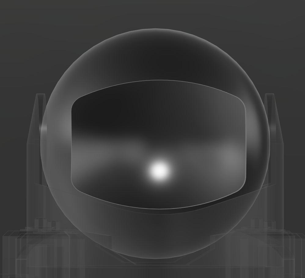
after getting the code working, for 3d printing and scanning week, I went back to work on the design. for my design in 3d printing and scanning week, I wanted to use a scaled down version of my final and make it print in place, but also used that as an excuse to fix some bad designs, like the head, which I completely redesigned to make it more like the reference.
PCB design & Manufacturing
This is a general outline of what I made, the making of can be found on my week 10 page
For the final, I made a bunch of PCBS
The Learning moment: Battery
The battery board was the one I used to learn how to etch boards. setting that aside, the actual board design was a tp4057, basically the older brother of the widely popular tp4056. I would of used a tp4056 if I could of found one, but the 4057 was available on digikey and the 4056 wasn't.
PCB Etching
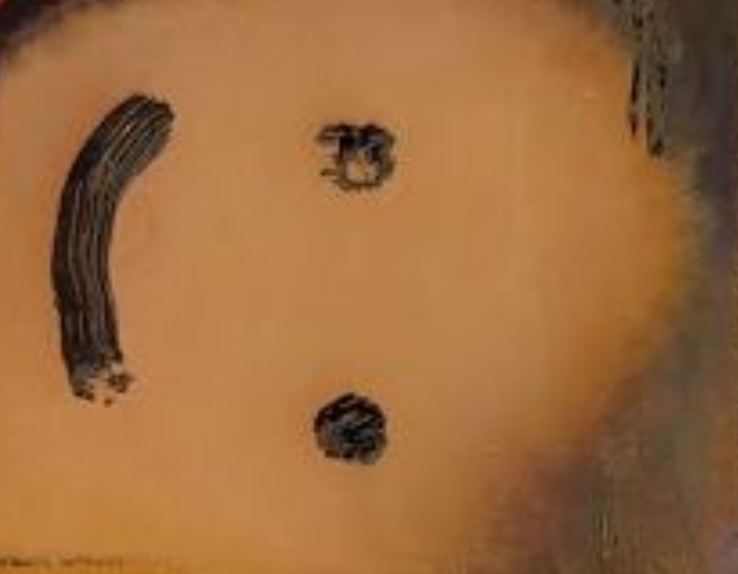
I was entirely new to PCB etching starting on the battery. I started by looking online, where I found this youtube tutorial for general use and this tutorial with a promising process to speed up etching using a sponge. I started with a simple sharpie and a smiley face, which came out well and proved that my ferric chloride actually worked. It also proved the sponge method was really strong, as it took around 1-2 minutes to etch that face
Getting Complicated with Etching
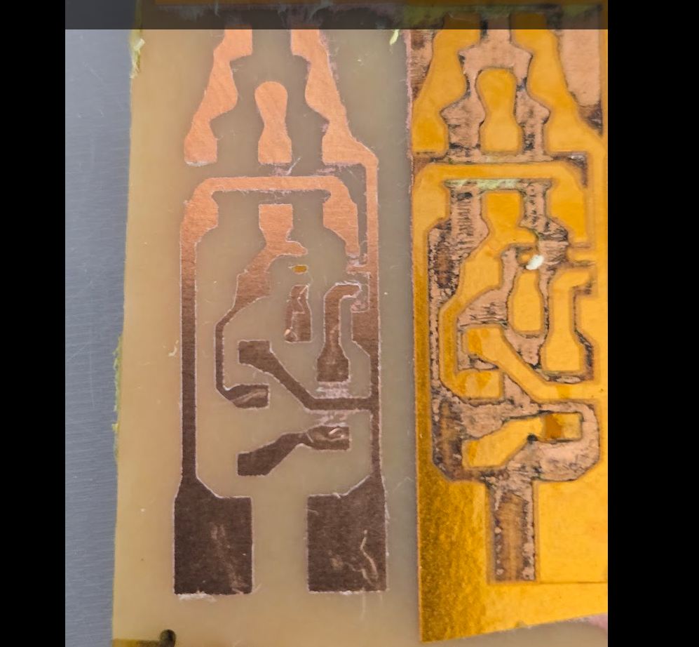
After proving the effectiveness of my ferric chloride and the sponge method, I started to work to figure out how I could make a board without using a lot of materials. For this, I discovered that my previous making of a solder stencil with pencil could translate really well here. After alot of testing, outlined in my week 10 documentation, I found that kapton tape was easy to laser cut and was thin enough to not get easily ripped off when rubbing with a sponge. Through that, I was able to laser cut the negative of the boards f.cu, which then allowed me to etch away everything but the traces and pads, giving me the result pictured
after a lot of thinking, I realized that I do not trust myself to get it right first time, and don't want to risk setting my entire project (and lab) alight. Therefore I decided to not use this in my final, and instead use the board that I've used in the path, the now offsale amazon link being (here)[https://www.amazon.com/dp/B0BN8BQ6L4]. If its offsale, it was a compact usb C 1 amp charge discharge module.
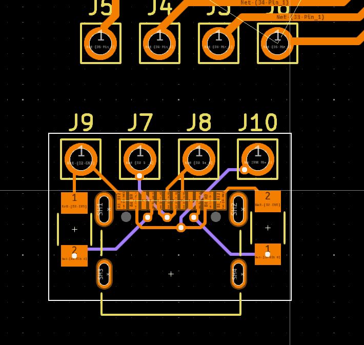
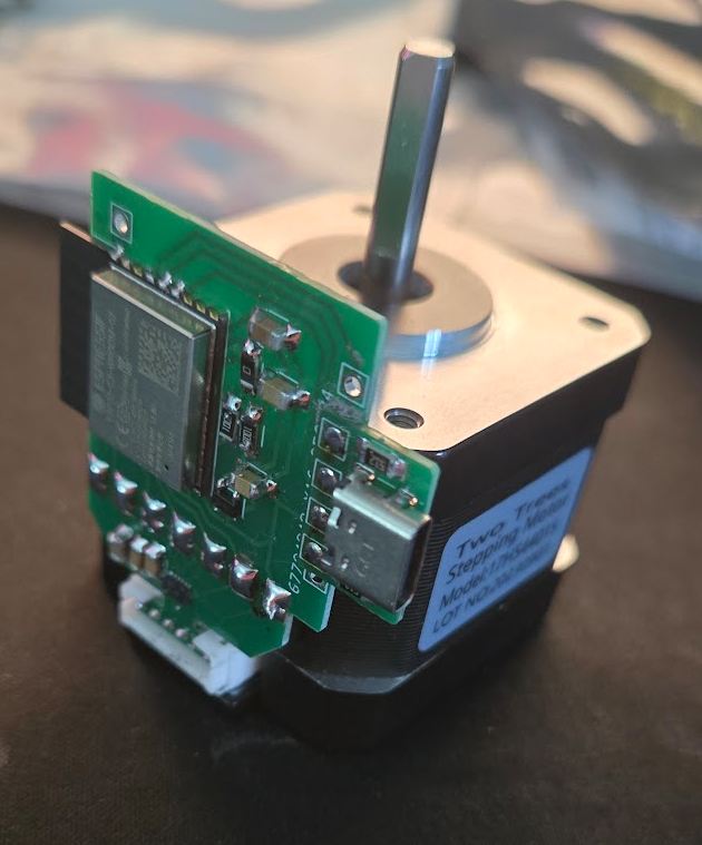
The most unconventional (and coolest): Stepper Driver
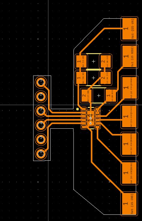
Because of the fact that im using a stepper motor combined with battery power, I needed a driver that was able to work with less than 8v, which is the standard for the drv8825 and a4988. I found that the drv8835, which is nothing like the 25 even though it sounds similar, would work for me. the main reason for using it was that low voltage, as it works with 2-12v, but it also features 1.5A max current, and a price of only 50 cents. Combined with the 3 filtering capacitors it needs, and the board, the entire driver cost only 2-3$. The unconventional part was the shape of it, as I designed it to be soldered directly to both the stepper through identifying the molex connector on mine (JST-XH), and then used pads to allow it to connect to the microcontroller "wirelessly" (its soldered directly on).
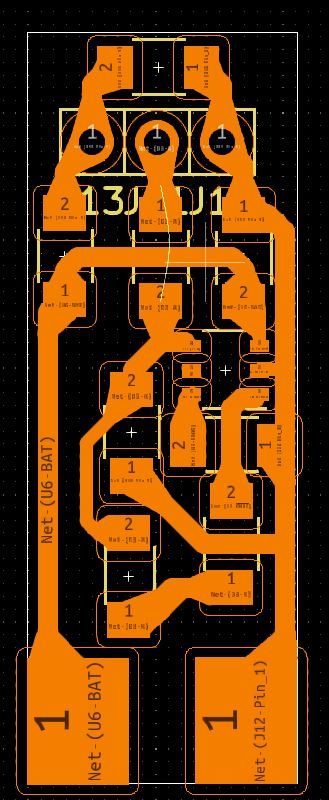
The most crowded: Microcontroller
Because of the fact that im using a esp32-c3 wroom module, and not a Xiao module like most of my classmates, I needed to have much more components on the side. I ended up with 6 resistors, capacitors, or voltage regulators on the main board. This board roughly followed the layout of my custom board I built before fab, but removed most pin headers and reformatted for single sided board. It also was designed to be milled, but I milled it, didn't get it working (due to coding issues with the stepper driver), but when resoldering it since I thought it might of been the voltage regulator, I ripped a trace and didn't have a backup. I just soldered one of the ones I ordered (I ordered all 4 boards in week 10 as a backup)
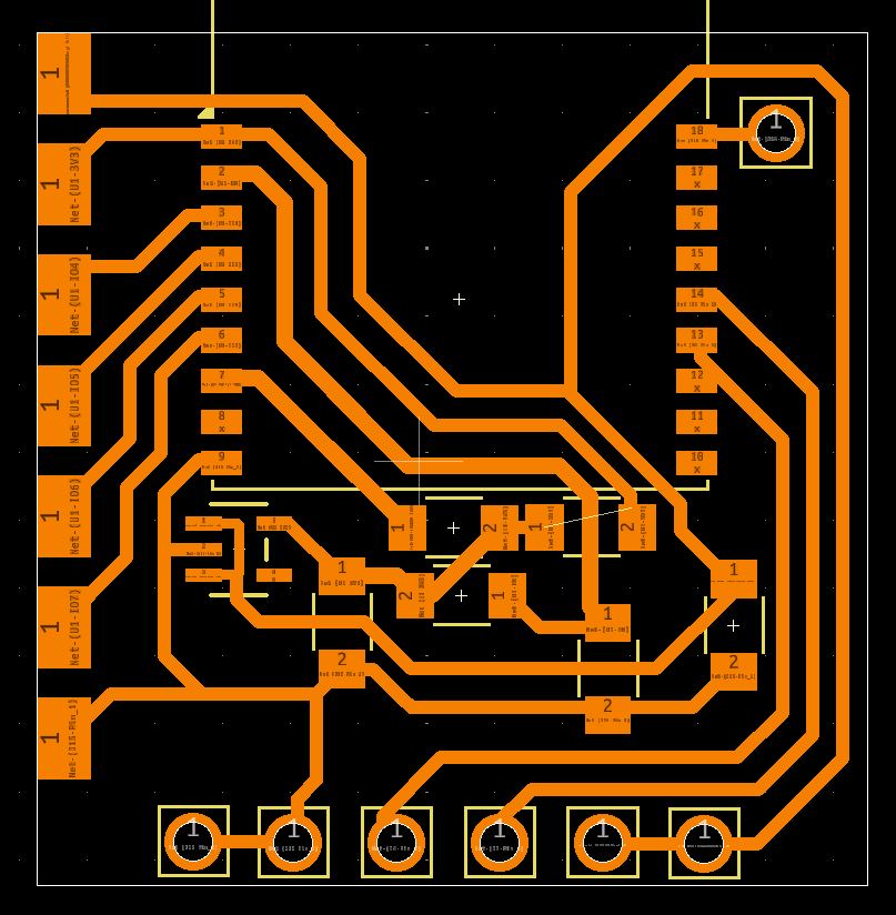
The smallest: USB-C
this is kind of a continuation of the microcontroller, but I needed a usb-c module to communicate between the microcontroller and a computer. I decided to make it a separate board since the microcontroller had the potential to be made through milling/etching, and the USB-C port I used in my other boards is way too small to have a chance of being milled/etched successfully. using USB without all the fancy gimmicks (just usb 2.0) is very easy, as its just 2 resistors soldered between the cc pins and ground.
Manufacturing
Etching
As I described above, I used etching to successfully make the battery board, which I described in much more detail in this section of week 10
Milling
I used milling for my first version of the microcontroller board, which was outlined in this section of week 10. Of all the processes, this was the most annoying as unlike etching, where if it failed it was very obvious, milling usually failed during soldering, which made me not trust the board and end up using a ordered board
Ordering
I used ordering for my first version of all the boards working together (except the battery). I outlined how to order in week8 for the group work, and the specifics for my final in week10.
PCB making hero shot
Midterm Review
As part of the midterm, I needed to figure out how I would get this done.
System Diagram
 While it may not look like much, this is all going to be cramped in the camera and the main focus is it being cheap
What still needs to be done and when
listed in order of importance, and also when I plan on doing them
- in molding and casting week, make the curved front see through panel
- in any of the weeks, finish the 3d design, and print it. This is high priority but will take a long time spread out
- in interface week, finish making the webserver, focusing on figuring out how to use that library that allows for an easy stream from the camera with actually good performance
- In integration week, work on hiding wires/fixing issues where needed
How I could do those
- For the mold, its just going to be learning how to in the week, and then either making it as the main goal of that week or using what I learned
- for the 3d design, I found really powerful plugin during machine week called gf gear generator, and used it there. Gears were an issue for me before, but with that plugin, I should be able to easily make gears.
- for the interface, I have each working separately, this will not take long at all
- Integration depends on everything else, as its the last step of the operation. Im planning on leaving a lot of time for it, and in general getting my final project done 4-2 weeks early
Tentative Gantt Chart
this gantt chart gives me A LOT of time before the final project is actually due, and this is the outline I plan to follow. Im leaving all the time at the end as im expecting to run into multiple hiccups, and don't want to procrastinate and run into those hiccups in the week that the project is due.
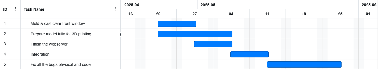
** As of 5/21, All code is nearing done, the good looking part of 3d design is done, but it needs to be made to move, The window molding failed horrifically so im going try a different process my brother suggested involving heating and bending acrylic, and filament just arrived so I won't have to worry about that
Bill Of Materials
| Part | Quantity | Total Price (USD) | Listing Price | Note | Note COMBINED |
|---|---|---|---|---|---|
| Stepper Motor | 2 | 12.14 | 7.06 | https://a.co/d/5kIdjjb | |
| Servo | 1 | 27.99 | https://a.co/d/gGgNJGU | Comes in a 4 pack, only 1 needed, incredibly common though so check storage | |
| 1Kg 3d filament | 1 | 19.99 | 19.99 | https://us.store.bambulab.com/products/petg-hf | |
| Stepper Driver PCB | 7.70 | For the custom driver, 2 are used | |||
| --- Driver Chip | 2 | 1.55 | https://www.digikey.com/en/products/detail/texas-instruments/DRV8835DSSR/3088201 | 1 per board | |
| --- 1206 10uF capacitor | 2 | 0.14 | https://www.digikey.com/en/products/detail/samsung-electro-mechanics/CL31A106MBHNNNE/5961220 | 1 per board, common capacitor size, order in bulk for large savings and later use | |
| --- 1206 0.1uF capacitor | 2 | 0.16 | https://www.digikey.com/en/products/detail/kemet/C1206C104K5RACTU/411248 | 2 per board, common capacitor size, order in bulk for large savings and later use | |
| --- PCB | 2 | 2.00 | probably impossible to mill/etch, order it, price based on JLCPCB, shipping excluded, comes in a pack of 5 | 1 per board | |
| Battery Charger PCB | 1.01 | ||||
| --- Battery Chip | 1 | 0.17 | https://www.digikey.com/en/products/detail/evvo/TP4057/22482076 | 1 per board | |
| --- 1206 10uF capacitor | 1 | 0.14 | https://www.digikey.com/en/products/detail/samsung-electro-mechanics/CL31A106MBHNNNE/5961220 | 1 per board, common capacitor size, order in bulk for large savings and later use | |
| --- 1206 470 ohm resistor | 1 | 0.10 | https://www.digikey.com/en/products/detail/stackpole-electronics-inc/RMCF1206JT470R/1753845 | 1 per board, common resistor size, order in bulk for large savings and later use | |
| --- 1206 10k ohm resistor | 1 | 0.10 | https://www.digikey.com/en/products/detail/stackpole-electronics-inc/RMCF1206ZT0R00/1756906 | 1 per board, common resistor size, order in bulk for large savings and later use | |
| --- 1206 LED | 1 | 0.10 | https://www.digikey.com/en/products/detail/liteon/LTST-C150GKT/269216 | 1 per board, common component, order in bulk for large savings and later use | |
| --- 1206 33k ohm resistor | 1 | 0.10 | https://www.digikey.com/en/products/detail/yageo/RC1206JR-0733KL/729282 | 1 per board | |
| --- 1206 1k ohm resistor | 1 | 0.10 | https://www.digikey.com/en/products/detail/yageo/RC1206FR-071KL/728387 | 1 per board, common resistor size, order in bulk for large savings and later use | |
| --- PCB | 1 | 0.20 | https://a.co/d/8GRjyGRE | Etched for me, can be milled, price of a copper sheet it's size | |
| USB C Module | 1 | 2.98 | |||
| --- USB C plug | 1 | 0.88 | https://www.digikey.com/en/products/detail/gct/USB4105-GF-A/11198441 | 1 per board | |
| --- 1206 5.1k ohm resistor | 2 | 0.10 | https://www.digikey.com/en/products/detail/stackpole-electronics-inc/RMCF1206JT5K10/1753850 | 2 per board, common resistor size, order in bulk for large savings and later use | |
| --- PCB | 1 | 2.00 | impossible to mill etch, order it, price based on JLCPCB, shipping excluded, comes in a pack of 5 | 1 per board | |
| Microcontroller | 1 | 4.57 | |||
| --- esp32-c3-wroom-02 | 1 | 3.58 | https://www.digikey.com/en/products/detail/espressif-systems/ESP32-C3-WROOM-02-N4/14553031 | 1 per board, it was 1.8$, im almost certain espressif raised prices due to tarrifs, so might go back down | |
| --- 1206 10k ohm resistor | 2 | 0.10 | https://www.digikey.com/en/products/detail/stackpole-electronics-inc/RMCF1206ZT0R00/1756906 | 2 per board, common resistor size, order in bulk for large savings and later use | |
| --- 1206 0.1uF capacitor | 2 | 0.14 | https://www.digikey.com/en/products/detail/samsung-electro-mechanics/CL31A106MBHNNNE/5961220 | 2 per board, common capacitor size, order in bulk for large savings and later use | |
| --- 3.3v regulator | 1 | 0.55 | https://www.digikey.com/en/products/detail/diodes-incorporated/AP2112K-3-3TRG1/4470746 | 1 per board, Really good regulator, I would suggest buying in bulk and using for other projects | |
| --- PCB | 1 | 0.20 | https://a.co/d/8GRjyGR | Milled this one, price is for a piece of copper the size of it | |
| COMBINED | 50.39 |
Continued 3d design
Heres where I finished the 3d design. This entailed really minor changes to the looks of the design, but mainly adding everything that would eventually make it move
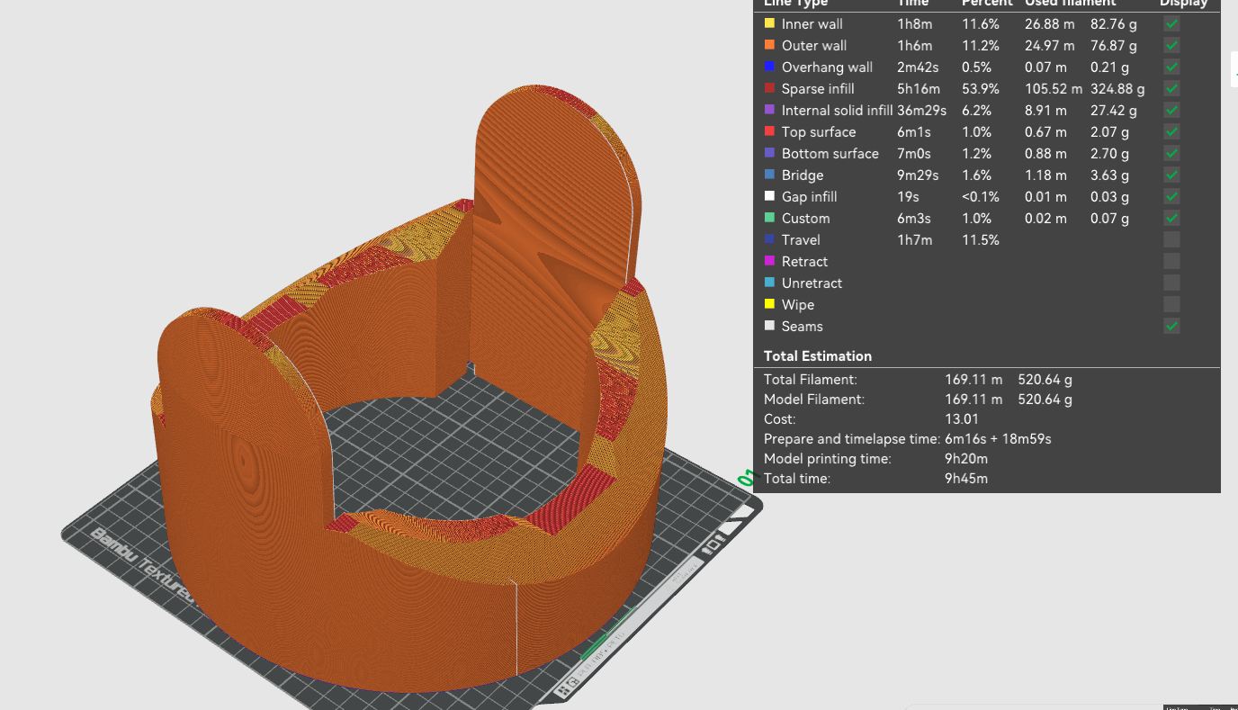 Heres why I wanted to optimize. The current model was 500 grams for just the midsection, but I am confident I can get it down to under a kilogram of filament for at least the 2 parts of the base.
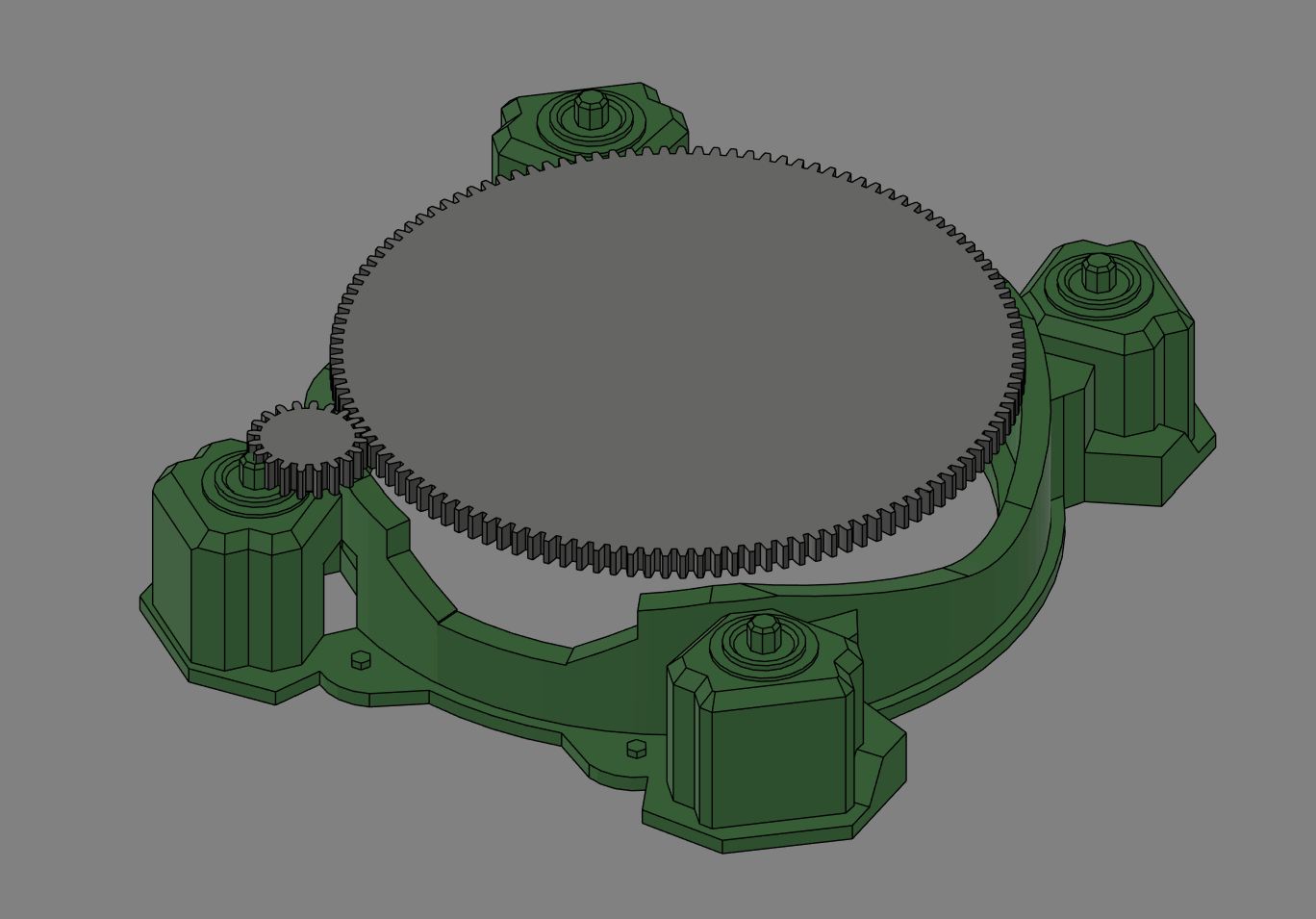
I also started on the motion in my design. This image is a rough sketch of what the gearing for the base will be like
Applications and Implications, Project Development
Final Project Answers
What will it do?
My Final project will recreate the "evil eye" from the videogame Rainbow Six Siege as close as I can get it. This includes 1. Infinite Rotation - In the game, the base can rotate around infinitely, so that means that there can be no physical connections between the two pieces. I looked into sliprings to allow for those connections, but they are really expensive or really unreliable. 2. Wireless Control - Again, in the game the "operators" use their phone to see a feed and look around with the camera. Im hoping to replicate that with a webserver that displays the camera output and has a joystick for looking around
Who's done what beforehand?
While nobody has made a camera that can infinitely rotate around, a lot of people have made pan tilt zoom cameras out of 2 servos. While a servo is promising for moving the upper head, a servo that could move the head up would cost about as the entire other half of the project and require much more power then a geared up stepper. Also, the camera has a lot of documentation, but an open camera that allows me to make my own website was hard to even find the library, and I don't think anybody has used this xiao cam with movement.
What sources will you use?
Datasheets will be really strong, especially for any chips I use. I will also be using the arduino examples heavily, especially when figuring out the camera. For reference in the physical design.
What will you design?
I plan to import this model into fusion and design off of that I will use no pre-made files when fabricating, instead creating everything with help of that reference but also then rigging it with mechanisms so that it can actually move.
What materials and components will be used?
The majority of it will be 3d printed, probably with PETG as thats what I have lying around. Im also going to use clear acrlyc, probably 1/4th inch thick for the windows. On the electronics side, it will use 2 stepper motors and their required drivers, 2 microcontrollers, one definitely being the seeed xiao esp32-s3 sense because of its built in camera, and another being some wifi enabled microcontroller, likely another esp series chip. In order to power it all, it will use a battery management board to supply a stable voltage, which will be connected to a single 18650 3.7v atleast 2500mah cell each.
Where will come from?
In order to allow other people to make this (I dont plan on selling it or anything) I will buy from only Amazon or Digikey. For the 18650, I get them from a battery wholesaler in town but if there is none near whoever else wants to make this I've used 18650 battery store in the past with no issues. Be warned that I think it only does US and adjacent shipping, but any 18650 cell will do
How much will they cost?
The second largest goal in this project was making it cheap. As seen in my bill of materials on my final project from midterm. In total, as of midterm the project will cost 50.39 total, but adding in the cost of acrylic it will be around 54$ of materials for the entire project.
What parts and systems will be made?
Everything past the most basic material will be made in house. I am going to make the gears, use the experience I got from the group work to make 3d printed bearings, and generally anything that can be made on the 3d printer will be. I want this to be easy to access, so maybe the most advanced rare material will be the screws that hold the stepper in place, if I can't find a 3d printed way for that
What processes will be used?
The main brunt will be 3d printing, but I also am going to laser cut out the acrylic and use heat to bend it into the circular shape for the window. I will also be using PCB milling, and maybe etching using a laser cut mask. I will also be using unconventional pcb design for the stepper drivers, as they are soldered right onto the servo itself
What questions need to be answered?
- Battery Life
- Rotation Speed
- Camera Quality
- Latency
How will it be evaluated?
- Battery Life: Spin it around until power runs out
- Rotation Speed: Measure time for 1 full rotation, or alternatively find out max speed of the stepper before putting it in, and calculate with the gear ratio
- Camera Quality: just watch it for a bit, while it moves, to see if theres any tearing or dropped frames in the stream
- Latency: Put something up to the camera, see how long it takes for it to appear on the phone
As of right now...
What tasks have been completed?
The Electronics are entirely finished, and the 3d design is completed.
What tasks remain?
I need to print out and post process the 3d design to smooth it, cut the window out of acrylic and bend it, and after getting all that assemble it all together.
what has worked? what hasn't
as of so far, most of the electronics worked first try, but due to the weird way of interfacing with the drv8835 (it uses phase/enable pins instead of a dir/step pin like im used to), Getting it to work required guessing 16 times until the step order was correct and it spun. Same for the camera, where the code for the library didn't have an easy way to get the raw camera feed onto a website I made, so I had to find a different library that gave it, and then build a website around how it gave that link. The battery board also was a failure, just because I don't want to burn down the building, and thats an easy way to burn down the building.
what questions need to be resolved?
I need to figure out how I will bend the acrylic, as my brother told me it was possible but it wasn't anywhere on his documentation so I'll have to research it. Also, due to the way my gears will eventually mesh together I will probably need some intermediate stage for the bottom gear.
what will happen when?
While im not a fan of direct "this will happen on this date", I know that I will finish the 3d design, start printing it out, then start figuring out the window, which I will hopefully finish once all the parts of the 3d prints are done, which will then allow me to smooth and paint them, before putting it all together.
what have you learned?
Electronics design was a big part, as well as advanced stepper usage, advanced 3d design based on a reference, optimizing a 3d design for movement, laser cutting non-flat objects, and programming a multi-node network.
System Integration
During this week, I designed the final PCB to hold the camera, redesigned the other esp pcb to be more compact, and finished the 3d design, which allowed me to start printing out part of it that week. Much more detail can be found on its page, here
1 week before its due
1 week before it was due, the weeks was a answer a set of questions as we completed our final project. For my final as of right now, I am almost done with my 3d design, with the only thing left being the head, as well as done with printing and moving the 2 body pieces. I also have the electronics all completed, including how I will power them and have how they are going to be hidden done on the 2 base pieces.
What does it do?
My final project is a machine with an infinitely rotatable base that moves around a camera that can look in full 360 degrees. It has an internal battery, and with the exception of the windows, is fully 3d printed and painted
Who’s done what beforehand?
Pan tilt zoom cameras are pretty common projects. This is what I would call my machine if I only had 3 words, but its very different from the rest in its mechanics. Specifically, almost all the projects, this one being a good one. The difference is while those use servos, mine use steppers because. 1. I need high torque, a geared stepper can provide that, and 2. I need to be able to rotate a lot, most servos tap out at 180 or 360 degrees, although there are infinite rotation variants.
What did you design?
With the help of this model as a reference, I designed all parts of my project by myself. The ESP-32-C3 board is from a pre-fab academy board I designed, but that was also designed by myself with the help of it's datasheet.
What sources did you use?
As I described above, the main source was what I used in my 3d design, which was this model. I also used various datasheets, the big ones being the ESP datasheet and my motor drivers datasheet
What materials and components were used?
Higher detail of this can be found in my bill of materials. In general though, I am using 3d printed components, printed in petg if at home and pla if at the lab. For the project, the 4 base pieces were made of PETG, the middle base was made of a single pla, and the head was made of multiple petg pieces. For the electronics, it used a mix of fr4 copper sheets and professionally made PCBs, with electronic components all coming from digikey. The besides for resistors, the important components are a 600mah voltage regulator, a seed studio sense esp32-s3 camera, a esp32-c3-wroom-02 module, 2 drv8835 low voltage stepper motor drivers, and a teyleton robot charge-discharge module
Where did they come from?
I prioritized getting the parts from digikey, but also had some of those charge discharge modules lying around, which came from amazon. The seeed also came from seeed studio, and both types of filament were purchased from bambu directly.
How much did they cost?
The total cost for all components was around 50$, with the main brunt being 1.25kg of filament, coming in at around 25$ total. The second most expensive were the 2 stepper motors, which were 7$ each. The rest of the components cost me more since I bought in bulk, but if buying the exact requirements for this will come out to around 15$ total, including ordering the PCBs (pre-tariffs).
What parts and systems were made?
The main focus was on PCBS, which are pretty good (for someone with no formal training), but also the making of the designs, especially around how this is going to be almost entirely 3d printed. In the code, I also made a node based network to communicate between the 2 steppers and their logic, and send the camera feed back onto a phone with a custom webserver made for this project.
What processes were used?
The processess used include 3d design 3d printing priming + painting electronical design network design system integration
What questions were answered?
What worked? What didn’t?
How was it evaluated?
What are the implications?
License
My product has no commercial value, and it's against the spirit of making something so community driven to then stab that community when they want to make it. Therefore, I decided on the Creative Commons Attribution Non-Commercial 4.0 International license. This allows anybody to create and edit my final project, but not profit off it as thats not in the spirit of this project
https://forums.autodesk.com/t5/fusion-design-validate-document/create-holes-in-a-hollow-sphere/td-p/8597242 followed this for creating holes in the sphere