Final Project
1. Initial Idea: “Official Passport Anti-Theft Alarm”
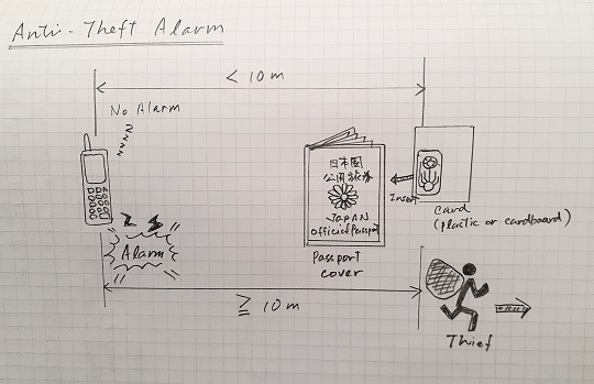
As of Week 1, I am thinking of making an anti-theft alarm system for official passports. The sketch image is attached herewith.
1-1. General Description
It consists of two components:
-
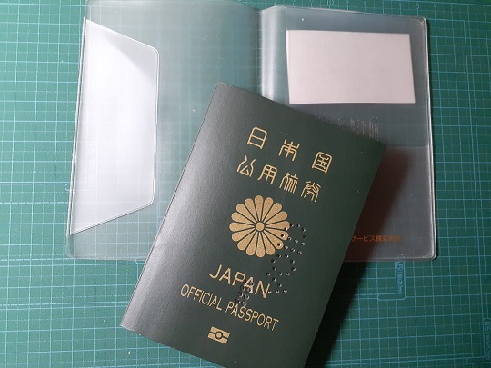
A small thin tag embedded in a thin cardboard-like paper card: Equipped with a bluetooth device powered by a button battery.
-
Mobile interface: Installed in the mobile phone.
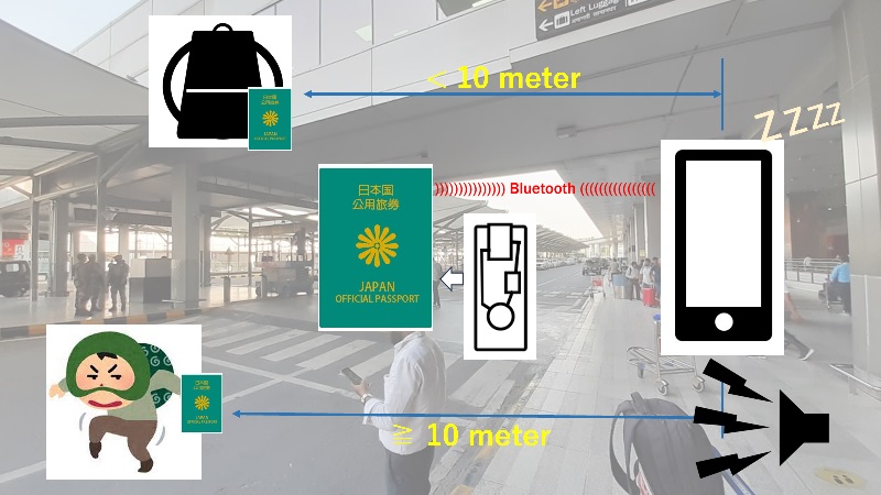
The tag is inserted into the vinyl cover for the passport. As long as the passport and the mobile phone stay in a close distance, within 10 meters for example, nothing happens. But the passport is brought away from the mobile phone, the mobile phone sounds the sirens.
1-2. Target Users
The primary target is those who are residing in foreign countries with a official passport issued by the Ministry of Foreign Affairs of their home country.
1-3. Background
-
When I was engaged in the foreign service as the head of the mission of the Japan International Cooperation Agency (JICA), I had always been facing the risk of the incidents that the JICA officials working in the same country, as expert, volunteer or administrative staff, have their official passport lost or stolen while they are traveling the third countries. Most of the incidents happen in the transit airports or cities before they reach the final destination. Once they lose their official passport, the head of the mission has to submit the first incident report to the JICA headquarters in Tokyo. Then the headquarters is blamed by the Ministry due to their mismanagement of the government asset, and that may affect our own performance assessment as the head of the mission.
-
I once took this issue so seriously and insisted that it’s useless for us to rely only on the self human efforts of the passport holder so that they should always stay alert and keep an eye on their passport. It’s impossible to minimize the risk only by the human efforts and I thought that there could be some room for technology to complement the human capacity. Therefore, I drafted a project proposal to prototype the theft alarm system locally in collaboration with the local FabLab in the same country and requested the JICA headquarters for the extra budget allocation to my office. Unfortunately my proposal was rejected by the officials saying that it’s not the matter for one country office alone to work on the solution for all the country missions around the world. Five years after this battle with the headquarters, JICA has not initiated any prototyping project yet and still been relying on the human efforts.
-
Another issue with regards to my relationship with JICA was that only a few officials were aware of the potential of decentralized production and open-source. Although there were already FabLabs near them, most of the officials have not paid attention to those labs and never thought of connecting their development cooperation programs to the FabLabs. I really wanted them to feel that it’s not that difficult to work on machine operations, soldering and assembly. Through this practice of local production of the open-source device at the local lab, I want them to learn more about FabLabs.
1-4. Findings from the Interview with the Officials
In Week 1 and 2, I visited the JICA officials to brief them about my final project at Fab Academy. In the same meeting, I asked under which circumstances the JICA officials had their passport lost or stolen. Here are the facts that I learned from the officials:
-
Before the pandemic, official passports were issued to 3,000 to 4,000 Japanese who were dispatched to foreign countries under JICA programs. The number decreased to 2,000 cases after JICA lifted the voluntary restrictions on the foreign assignments during the pandemic.
-
Here is the statistical data on the cases of lost passports, together with the number of cases other than lost passports. The latter include the cases in which their passports were stolen. The reason for zero case in FY2019 was that in response to COVID-19 pandemic, JICA suspended the new foreign assignments of Japanese experts and volunteers and brought their officials, experts and volunteers in service back to Japan. It was also learned that there were few cases against the number of official passport issuance. But what is required is to reduce it to zero.
Fiscal Year Lost Passports Other Cases FY2016 9 3 FY2017 8 9 FY2018 7 4 FY2019 0 0 FY2020 1 1 FY2021 5 0 FY2022 2 2 -
Initially I thought that most of the cases occurred while the holders were on tour and temporarily staying in the transit countries. However, I was informed that the majority of the cases actually occurred in the countries of their assignment. When they open a bank account, take an exam, or take a domestic flight, they are requested to show their passport as their ID. While it is true that the JICA country offices take a policy to keep their official passports in the safe, there are some occasions when the holders have to use their official passports.
-
In some cases, they lost other valuables, such as a wallet and a driver’s lisence, together with the official passports. They put them in the same handbag, pouch or pochette. But in other cases, they took out of the bag their passport to show it as an ID and after using it, they failed in putting it back to their bag. In this case they were unaware of the misplacement.
-
The officials were of the view that it is true that the mobile phone would probably be the last item that the users would keep in a close distance although there is still a slight risk that the mobile phone could also be misplaced or stolen.
-
Every time that such cases are reported, JICA has to report to the Japanese Ministry of Foreign Affairs. They are in dire need for a measure to control the risk and reduce the number of cases to zero. However, so far, they have not introduced any affordable countermeasure on this issue.
1-5. Past Projects
After sharing my ideas with my instructors, I was advised to study the following two projects below. Both of them are aiming at tracking the personal belongings so that they could minimize the risk of loss. The difference of my project is to prevent the users from going away from the item or to scare the theif and have him/her give up stealing the item.
Also, during the Regional Review Session for Asia earlier this week, I came to know about the following project by the Fab Academy participants in 2020. The downsizing the components as thin and small as possible is a challenge for me. I will further research on the past projects.
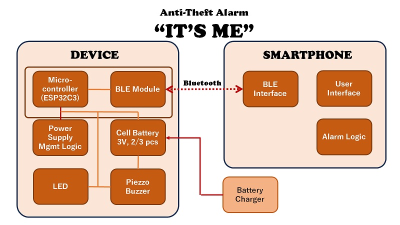
2. Project “IT’S ME”
2-1. Project Title
As part of the Weekly Assignment for Week 10, I considered the project title and decided to name it “IT’S ME”. It aims at symbolizing the following two objectives:
-
Anti-Theft Alarm: When the panic alarm starts ringing, the device will help the people around it to see it’ me who is steeling someone else’s belongings.
-
Mislaying Prevention: When the owner leaves his/her passport and goes away from it, the device, as well as the mobile app, starts ringing and appeals “Don’t leave me.”
2-2. Functional Requirements
-
Packaging: The device is packaged in a small box or a leather cover which is attached to the passport or kept with it in a backpack or a pochette.
-
Bluetooth: The device is linked to a smartphone via Bluetooth LE.
-
Panic Alarm: Once the device and the smartphone are separated by 10 to 20 meters, a panic alarm will sound both on the smartphone and the device. The primary objective of the panic alarm embedded in the device is to scare the theif or to notify the holder, the alarm on the device side should be as high as 80 to 90 dB.
-
How To Stop Alarm: Because the panic alarm on the device side is to scare the theif, there is no system on the device to stop the alarm. It could be stopped on the smartphone side.
-
Power Supply: Two or three 3V coin batteries will be connected so that we could ensure the high volume of the panic alarm.
-
Power On/Off: The device is switched on and off every 10 second. Once it is switched on, the distance between the device and the smartphone is inspected. However, once the panic alarm starts ringing, this routine is overruled and the power is kept on until the alarm is stopped on the smartphone side.
-
LED: The device is equipped with an LED so that we could see if the power is on or off.
2-3. System Diagram
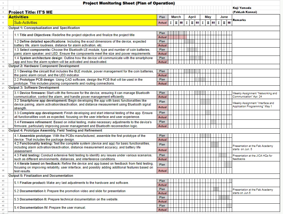
2-4. Project Implementation Schedule
The following is the comprehensive list of the tasks to be completed to get the project implemented toward the end of June 2024. You may wish to monitor the progress on the Google Spreadsheet.
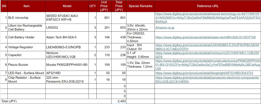
2-5. BOM
The following is the project BOM. Please note that the attached table is tentative as of April 10 because it hasn’t gone through the consultation with my instructor yet. The attached table will be replaced by updated information in a couple of weeks. You could also check the updated BOM on the following Google Spreadsheet.
3. Prototyping
3-1. Board Selection
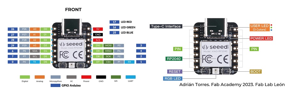
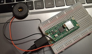
During the weekly assignment for Week 8. Electronics Design, I selected Seeed Xiao ESP32C3 as my microcontroller. As I further proceeded to the following few weeks, however, I have faced a series of errors in compiling and uploading with Arduino IDE, as described in my individual assignment pages for Week 9. Output Devices and Week 11. Input Devices. That made me feel that I should work on the alternative: Raspberry Pi Pico W.
Both controller boards have had Bluetooth/Wifi communication devices embedded. My evaluation criteria for board selection is therefore (i) Operating voltage to make the buzzer as loud as possible; and (ii) Power consumption to save the battery as long as possible.
Seeed Xiao ESP32C3 Pinout Diagram
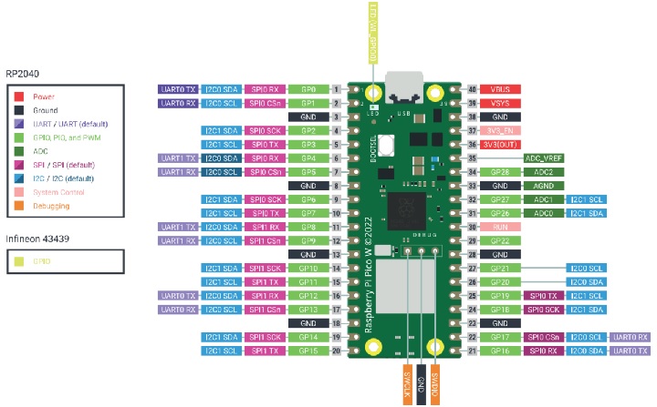
Raspberry Pi Pico W Pinout Diagram
| Xiao ESP32C3 | Raspberry Pi Pico W | |
|---|---|---|
| Operating Range | 3.3V/200mA | 5V/18.06mA |
| Power Consumption during BLE Usage | < 10mA | 301mA |
| Power Consumption during Deep Sleep | 44uA | 1.3mA |
| Note: I collected these data from different sources and the numbers must have some inconsistencies. |
It looks like it’s up to which I would like to place a higher priority, high voltage (volume of the buzzer) or power consumption. Currently my priority is placed on the volume of the buzzer, I feel I should start with Pico W.
Note: I wrote this sub-section after I wrote 3-3. Buzzer. Although I currently only post the buzzer test result using Arduino UNO board, I would like to make sure that I would do the similar test with Pico W board later and post the result.
3-2. Battery
3-3. Buzzer
3-3-1. Desk Survey on Buzzers and Speakers
In order to understand the mechanism to enhance the loudness of the alarm, I did a little desk survey about buzzers and speakers. Here is my findings.
Sound is created as vibration of air. The pressure of air when sound is transmitted as a vibration is called sound pressure. The number of times per second that the air pressure becomes dense or sparse, and the number of times this change occurs is called the frequency.
Sound Volume and Sound Pressure Level (Loudness)
Sound pressure level refers to the loudness of sound. The unit is dB, and a louder sound pressure level means a louder sound. Generally, the smallest sound level that can be recognized by humans is 0dB, and it is said to be about 60dB for an ordinary conversation and about 100dB for the sound of a train passing.
Pitch ofthe Sound
The frequency range of sound that can be heard by the human ear is generally said to be from 20Hz to 20,000Hz (20kHz). Among these, sounds in the range of 2kHz to 4kHz can be heard most efficiently, and this frequency range is often used for sound components.
What is a Buzzer?
A component that generates an alarm or electronic sound is called a buzzer. Among these, piezoelectric buzzers are those that apply piezoelectric ceramics. Buzzers are used for alarms and warning sounds because they generate sounds of a specific frequency. Speakers, on the other hand, generate sounds of a wide range of frequencies and are used for music and music reproduction.
When vibrations of the same frequency as the natural frequency of an individual object are combined, the object begins to vibrate. This phenomenon is called resonance, and the frequency at which this resonance occurs is called the resonant frequency. In acoustic reduction, when sound waves with a frequency close to the natural frequency are input to the sounding element, the amplitude becomes very large, and this frequency is called the resonance frequency.
The piezoelectric buzzer produces a large sound volume by generating sound waves close to the natural frequency of the resonator “case” with a built-in vibrating plate. The advantages of piezoelectric buzzers are that they consume little power, weigh less because they can be composed of fewer parts, and can easily be made thinner.
A piezoelectric sounder incorporates a piezoelectric diaphragm in a plastic case (resonator). An oscillation circuit built into the plastic case of this piezoelectric sounder is a “piezoelectric buzzer,” which produces sound simply by applying a DC voltage with a battery. In a nutshell, the buzzer has a piezoelectric circuit, but the sounder has no circuit. Therefore, when a sounder is used, a device that allows an external signal input to produce a loud sound needs to be added. Piezoelectric buzzers, on the other hand, have an oscillation circuit built into the sounder’s case or are used in combination with an external dedicated oscillation circuit, and the sounding frequency is usually fixed at one unique level.
Role of the Resonator (Case)
The case makes use of the resonance effect to produce a louder sound. For example, if the sound pressure peak of the vibrating plate and the sound pressure peak increased in the case occur at different frequencies, the mechanism is that when the two are combined, the sound pressure is increased by 10 to 20dB due to the resonance effect.
Mechanism of Changing the Sound Scale and Volume
The pitch (frequency) of a piezoelectric buzzer is fixed for each product and cannot be changed. With piezoelectric sounders, it is possible to change the pitch (frequency) by the frequency of the AC voltage. However, the volume varies depending on the frequency.
The volume of a piezoelectric buzzer/sounder can be increased by increasing the input voltage. However, we have to bear in mind that we are not always able to increase the input volutage for the product to the level beyond the capacity of the product.
Basic Schematics of Piezoelectric Sounding Components
The general drive circuit for piezoelectric sounders is a circuit that is directly driven by an IC; the piezoelectric sounder is driven to sound according to the signal input from the IC. Therefore, the frequency and sound pressure level of the sound depends on the frequency and voltage of the signal input from the IC.
If the voltage input to the piezoelectric sounder is increased, the voltage level can also be increased. Therefore, if a separate power supply voltage higher than the voltage that can be input from the IC can be provided, a larger sound pressure level can be obtained by using a transistor together.
3-3-2. Desk Survey on the Panic Alarms in the Market
In order to understand the mechanism of the buzzer, I first worked on reverse-engineering a security alarm available in the market. Security alarms are being sold at many dollar shops in Japan, which means that the whole package is being sold at JPY100. Security alarems are worn by schoolchildren to protect themselves. Once they are feeling danger and scared, they pull the string attached to the switch and then the loud alarm sound will go off. This sound attracts attentions of the people around and scares the villains who are trying to do something to do harm to the kids.


Alarm sound is almost similar among the different security alarms.
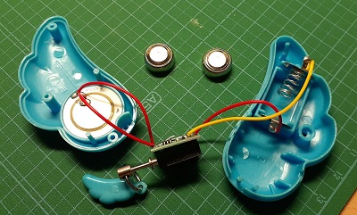
I bought one at the nearest dollor shop and took it apart. It turned out that it was composed of the following three major components.
| SN | Key Item | Qty | Remarks | Photo |
|---|---|---|---|---|
| 1 | Coin Battery LR44 1.5V | 2 | Total Voltage: 3V |  |
| 2 | Piezzo Speaker | 1 | 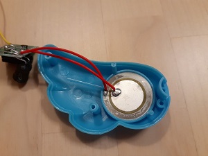 |
|
| 3 | Board | 1 | Pull Switch x1, Alarm Boost Inductor x1, Alarm IC x1, Hall IC? x1, Capacitor? x1 |
On the board, I saw a pull switch, an alarm boost inductor, an alarm IC, and most probably a hall IC (or a Hall Effect sensor) and a capacitor. The reason I put a question mark on the hall IC and the capacitor is I am not sure if they are the ones.
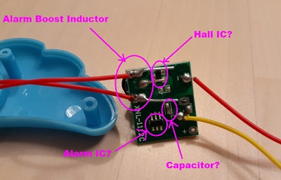
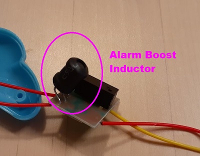
Alarm Booster Inductor is probably a DC-to-DC converter that increases voltage, while decreasing current, from its input (Supply Voltage 3V) to its output (load). Alarm IC is a sound-generation IC that could make several siren sounds. Hall IC is an integrated circuit that converts the strength of a magnetic field into an electrical signal. It can be used to create non-contact switches that operate based on the strength of the magnetic field. And capacitor is an electronic component that stores electric charge, blocks direct current signals, and allows alternating current signals to pass through.
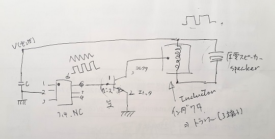
I searched for the schematic of the panic alarm on the Internet. I couldn’t find exact the same one for the alarm I had with me. I tried to sketch the schematic by myself.
But I found a few schematics for the similar alarms. These are probably the best ones I could find. While the first one seems to be having the booster inductor, the second one does without it.
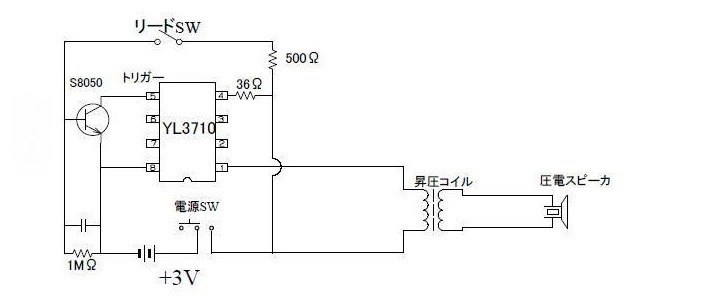
[Source] http://ku3gururi.starfree.jp/toy/tool/checkero.htm
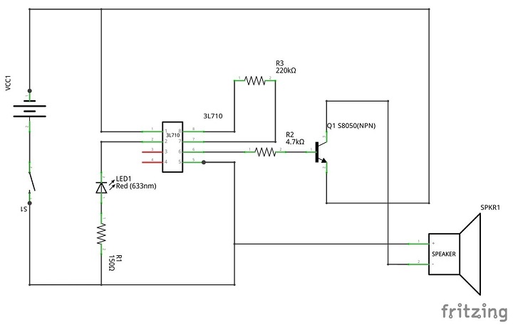
[Source] https://mnishikawa.hatenablog.com/entry/2020/04/30/221136
How big can we make the buzzer sound with the two CR2032 coin batteries in serial connection (6V)? Here is the test result.
3-3-3. Making the Siren Sound for the Device
In parallel to the work on the circuit design, I worked on the program for the siren sound for the device. Based on the above understanding about the mechanism how buzzers beep, I have thought of the two approaches: use of a passive buzzer or an active buzzer. For now, using Arduino UNO, I have designed the Option 1 with a passive buzzer.
Option 1: Passive Buzzer
//by Sintron
//2017.03.20

#include "pitches.h"

// notes in the melody:
int melody[] = {
  NOTE_A5, NOTE_A4};
int duration = 1000;  // 100 miliseconds
 int buzzer = 12 ;// setting controls the digital IO foot buzzer

void setup() {
   pinMode (buzzer, OUTPUT) ;// set the digital IO pin mode, OUTPUT out of Wen
}

void loop() {
  for (int thisNote = 0; thisNote < 2; thisNote++) {
    // pin8 output the voice, every scale is 0.5 sencond
    tone(8, melody[thisNote], duration);
    // Output the voice after several minutes
    delay(1000);
  }

  // restart after one seconds
  delay(100);
}
Option 2: Piezoelectric Speaker
I have tentatively decided to use the Raspberry Pi Pico W board for my final project after the test about Option 1. Therefore, for the second test, I tried to try piezoelectric speaker with RPI Pico W. First I reviewed the global session in Week 9 (Output Devices) and found one code which I thought would serve for my purpose.
I was not so satisfied with the monotone buzzer sound that the active buzzer sends out. As a result of my desk research, I came to know how I could control the voltage and change the tone, using the PWM (pulse width modulation).
| + | pin 0 |
|---|---|
| - | pin 1 |
//
// hello.TB67H451.RP2040.audio.ino
//    XIAO RP2040 TB67H451 H-bridge audio hello-world
//
// Neil Gershenfeld 11/7/23
//
// This work may be reproduced, modified, distributed,
// performed, and displayed for any purpose, but must
// acknowledge this project. Copyright is retained and
// must be preserved. The work is provided as is; no
// warranty is provided, and users accept all liability.
//

uint32_t duty_min = int(0.1*65535);
uint32_t duty_max = int(0.4*65535);
uint32_t duration_us = 10000;

void setup() {
  analogWriteFreq(50000);
  analogWriteRange(65535);
  }

void loop() {
  //
  // square wave soft ramp
  //
  for (uint32_t delay_us = 5000; delay_us > 500; delay_us -= 50) {
    uint32_t cycles = duration_us/delay_us;
    for (uint32_t i = 0; i < cycles; ++i) {
      analogWrite(0,0);
      analogWrite(1,duty_min);
      delayMicroseconds(delay_us);
      //
      analogWrite(0,duty_min);
      analogWrite(1,0);
      delayMicroseconds(delay_us);
      }
    }
  //
  // square wave loud ramp
  //
  for (uint32_t delay_us = 5000; delay_us > 500; delay_us -= 50) {
    uint32_t cycles = duration_us/delay_us;
    for (uint32_t i = 0; i < cycles; ++i) {
      analogWrite(0,0);
      analogWrite(1,duty_max);
      delayMicroseconds(delay_us);
      //
      analogWrite(0,duty_max);
      analogWrite(1,0);
      delayMicroseconds(delay_us);
      }
    }
  }
With this test, I could make sure that the code indicated in the global session could be used in my final project. However, althought this alarm sound was fine, the sound volume is still too small.
3-4. Central-Peripheral Bluetooth Low Energy (BLE) Communication and User Interface
In Week13, where I mainly featured my experience in Xiao ESP32C3 via Arduino IDE, I learned how to have my peripheral board send out a beacon for BLE connection (See Individual Assignment for Week13). Then in Week14, I spent most of my time for individual assignment, developing the user interface with the MIT App Inventor. As of the end of Week14, I could only do the BLE connection test twice with Raspberry Pi Pico W board and Xiao ESP32C3 board. Despite a few technical glitches, it seemed that I had better stick to Xiao ESP32C3 as my main board (See Individual Assignment for Week14).
My design idea as of the beginning of the Week13 was that:
-
Once the central and peripheral lose the Bluetooth connection, the central (Mobile App) will play the siren and the peripheral (device) will also start playing the siren.
-
Then the user (mobile phone holder) could send a signal message to the device to stop the siren.
However, here I realized that once they lose the BLE connection, there would be no way for the mobile phone holder to remote-control the device to turn off the siren. I thought of the alternative approaches. Due to the time remaining, I decided to make it as simple as possible so that the only event that could trigger the siren on both central and peripheral sides could the the Bluetooth disconnection.
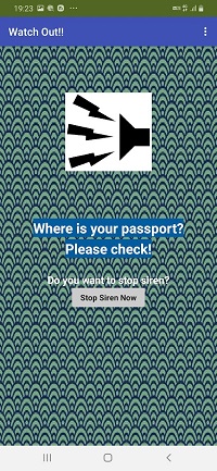
Then I should think of the first set-up of the central-peripheral connection. At this point of time, as soon as the passport-holder loads batteries on the device, it automatically starts playing siren and it keeps making noise until the user completes the Bluetooth connection set-up. Therefore, the users have to set up the Bluetooth connection as quickly as possible and for that reason, the operations on the mobile app should be as simple as possible.
So the design of the TOP page was made very simple: “Scan”, “Stop Scan”, “Connect” and “Disconnect”. Users are supposed to scan the beacons and identify the device they want to connect. Then they stop scanning and press the “Connect” button. After the mobile phone and the device are paired up first and if they are disconnected, the app starts playing the siren on the central side and moves to the Second page, where the users could stop the siren of their mobile phone.
I added the “Disconnect” button to the TOP page in case the users want to know where the device is even it is located within the Bluetooth range.
With these considerations, I have reached the final design as shown in the following two screenshots.