Week 9. Output devices
Group assignment
Tasks
- measure the power consumption of an output device
we tried three methods for measuring power consumption of motor.
- with power supply
- with multimeter
- with Arduino + program simulation LTspice
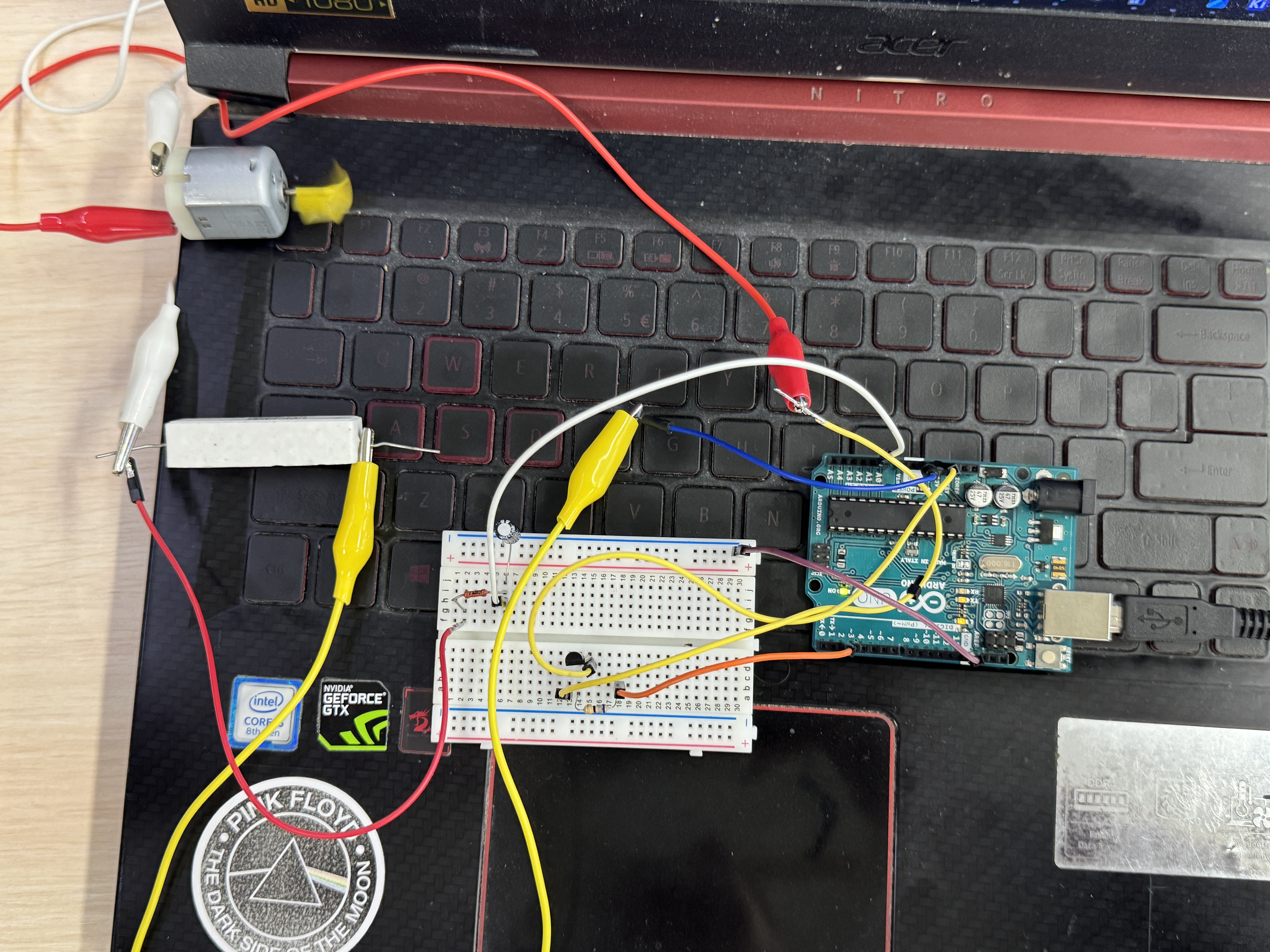
A circuit we made with breadboard and Arduino board.
This circuit diagram created in LT SPICE.
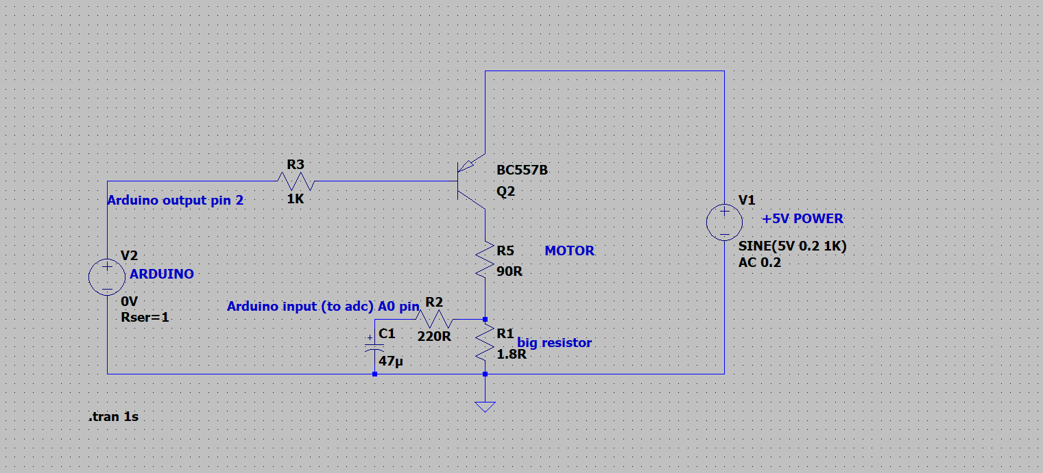
Simulated this circuit in the program
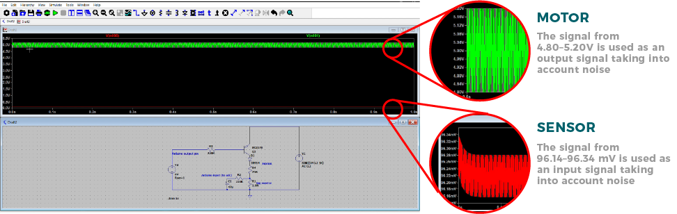 Image taken from Areg’s documentation. Thanks for illustrative presentation.
The aim of this experiment was to make a sensor from a motor. It’s measuring voltage difference between resistors. When motor takes resistance external encounter resistance it’s current encases. R1, R2, and C1 also take increase of current as they are connected in series with the motor. This part takes role of sensor for Arduino(pin A0). The program detects increase of current and turns off the motor.
int motor = 2;
int sensor = A0;

void setup()
{
  // put your setup code here, to run once:
  Serial.begin(115200);
  pinMode(motor,OUTPUT);
  pinMode(sensor,INPUT);
  digitalWrite(motor, 0);
  delay(1000);
}

void loop()
{
  int var = analogRead(sensor);
  Serial.print(var * 0.0049); // convert the values from the analog pin (0-1023) to volts(0-5V) by applying a coefficient of 0.0048
  Serial.println(" V");


  if (var >=23)
  {
    // turns off PNP transistor
   digitalWrite(motor,1);
   delay(5000);
   // turns on PNP transistor
   digitalWrite(motor,0);
   delay(1000);
  }

  delay(100);
}
This system can be integrated in automated systems with motor like elevator doors.
Individual assignment
For output devices I decided to use a water pump which will be useful for my final project. I’ve found some pumps and ultrasound fog maker.
At first tried the fog maker with power supply. I find out it starts to work from 11V to 24V.
I tried to use 24 V power supply. But I wanted to control the power of this device with transistor and microcontroller.
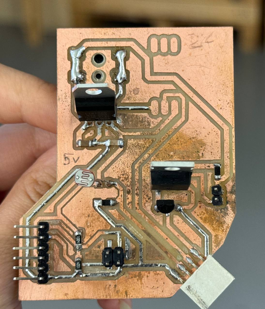
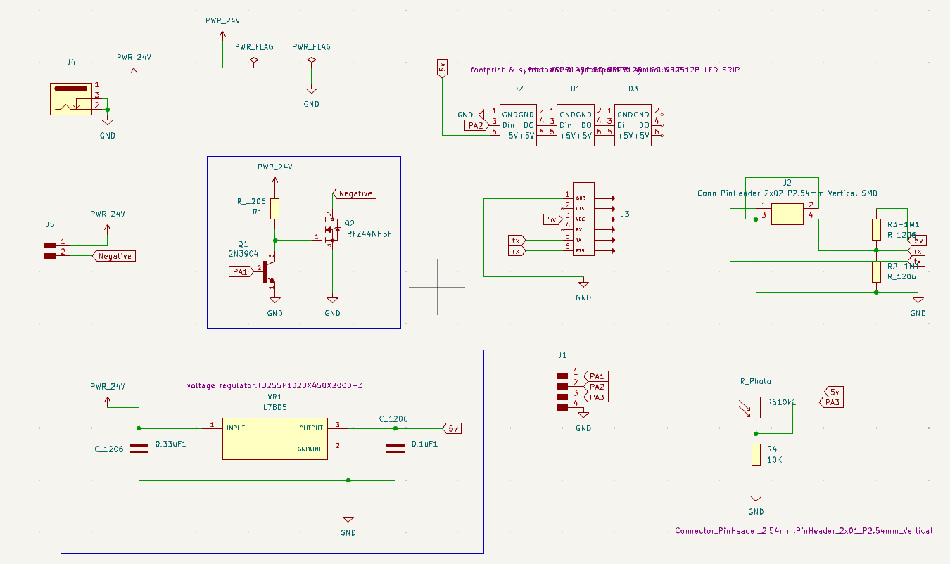
I made a new board where I can test Voltage Regulator and transistors with some devices inputs and outputs for final project. For this week I tried to control the fog maker with microcontroller and transistors schematic, where the device is powered by 24V and controlled by a pin on Microcontroller.
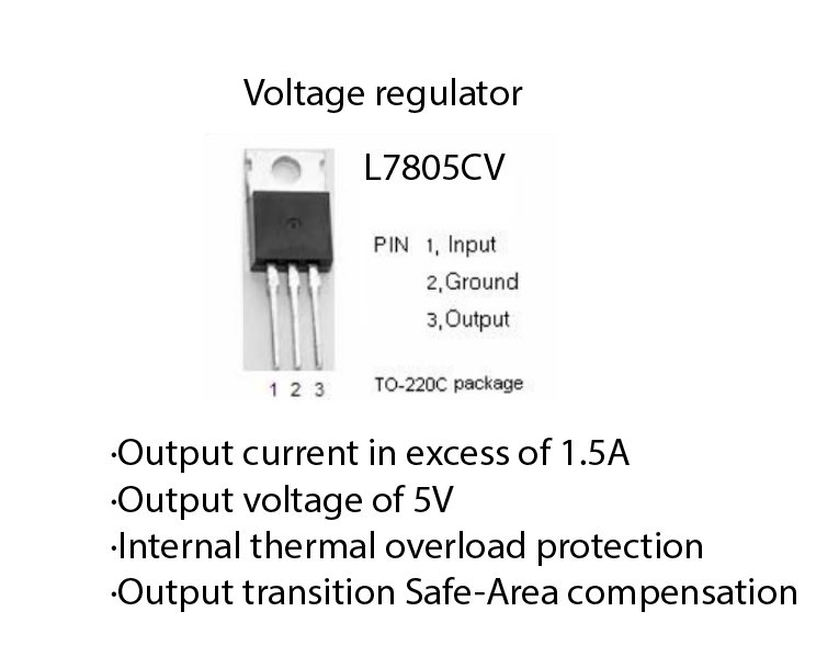
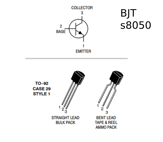

here I have jack for 24V input and output, voltage regulator (L7805CV) 24V to 5V, Transistor schematic with Mosfet (IRFZ44N) and BJT(s8050).
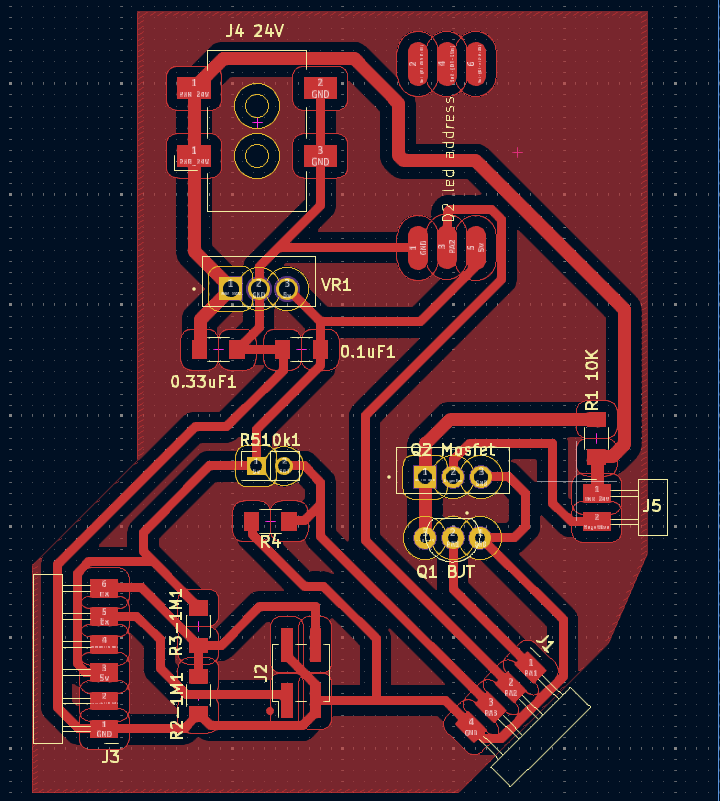
Connected with power supply 24V input, as well connected the fog maker device to 24V pin and negative power pin from transistors schematic.
Two transistors schematic is taken from this instruction. This schematic Shushan tried out for her final project and she advised me too. The reason of using two transistors (NPN and PNP) is that without NPN, the low voltage logic signal is insufficient to control the MOSFET. To control a MOSFET with a voltage of 12 V at the gate, here is used a low voltage logic signal.
” The MOSFET needs MORE than 5V to operate. The NPN can operate on 5V, it then provides switching of 12V on the MOSFET gate. ” (answer on the forum)
I used this schematic as well with 24V for my fog maker and on the output it managed to deliver about 23V and with ability to control on and off states with microcontroller.
Tested using Arduino board. Programmed pin 4 to switch on and off the device for 2 seconds.
int humidity=4;
void setup() {
  pinMode(humidity,OUTPUT);
}

void loop() {
  digitalWrite(humidity,HIGH);
  delay(2000);
  digitalWrite(humidity,LOW);
  delay(2000);
}
Transistor with LED
I tried to use a transistor. What I found is IRFZ44N mosfet.
I connect the gate with a digital pin on my Quentorres.


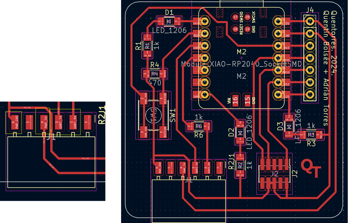
gate is powered by pin 1, which we can see is also turning on/off the LED on the board. And when it delays 5 seconds HIGH the transistor lets the LED on the breadboard to light.
This works as expected.
When I let the gate floating, LED gets powered from the 5V on the board and lights up. And when I plug the gate pin back, the transistor gets 3.3V and opens chain to provide power the LED.
code is simple pin toggle example
      #define pin 1

    void setup() {
      // put your setup code here, to run once:
      pinMode(pin, OUTPUT);

    }

    void loop() {
      // put your main code here, to run repeatedly:
      digitalWrite(pin, 1);
      delay(5000);
      digitalWrite(pin, 0);
      delay(5000);

    }
Servo motor
CS-939MG servo motor is what tried as an output device.
First, I tried to adjust rotation angle with Arduino code.
I opened example code for sweep on Arduino.
    #include <Servo.h>

    Servo myservo;  // create servo object to control a servo
    // twelve servo objects can be created on most boards


    void setup() {
      myservo.attach(1);  // attaches the servo on 1 pin to the servo object
    }

    void loop() {
      int pos;

      for (pos = 0; pos <= 180; pos += 1) { // goes from 0 degrees to 180 degrees
        // in steps of 1 degree
        myservo.write(pos);              // tell servo to go to position in variable 'pos'
        delay(15);                       // waits 15ms for the servo to reach the position
      }
      for (pos = 180; pos >= 0; pos -= 1) { // goes from 180 degrees to 0 degrees
        myservo.write(pos);              // tell servo to go to position in variable 'pos'
        delay(15);                       // waits 15ms for the servo to reach the position
      }
    }
Potentiometer
Then I tried to use with potentiometer
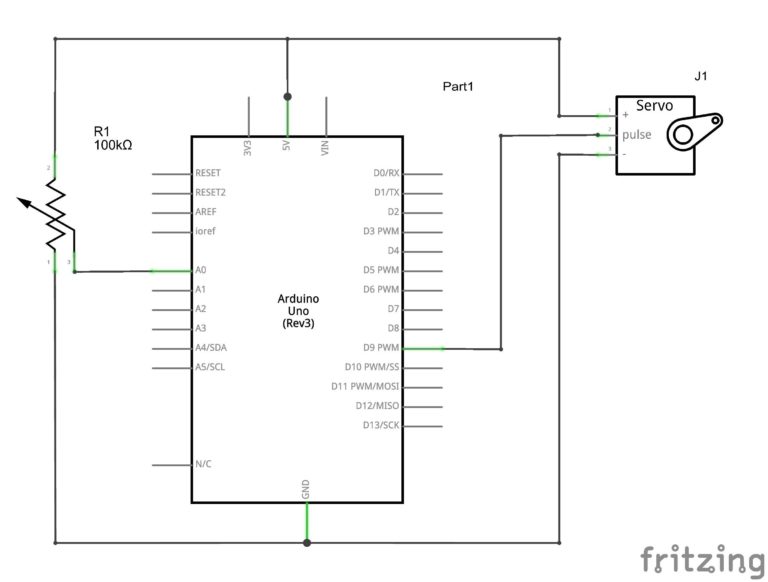
I used this schematic that I’ve found on Internet. It’s using Arduino board but I changed pins and used the RP2040 same way. I Connected the potentiometer to A0 analog pin and remaining pins same as in the schematic.
#include <Servo.h>

Servo servo1;
int potin;

void setup()
{
  servo1.attach(2);
}

void loop()
{
  potin = analogRead(A0);
  potin = map(potin, 0, 1023, 0, 180);
  servo1.write(potin);
  delay(15);
}
Servo tester
Additionally I used servo tester device to check it’s angular limits. it varies from 800 to 2200 values, which are from 0 to maximum possible angle of this servo.
Store page for this Servo tester HJ speed controller Tester for brushless servos 2X3 1-4 Servos / ESC.
Conclusion
This week I used few output devices and tried to control them with using PWM on my microcontroller and to switch them on and off with transistor. I used:
- Ultrasound fog maker and transistors
- LED and transistor
- Servo motor and potentiometer.