Week 8. Electronics Design
In Short
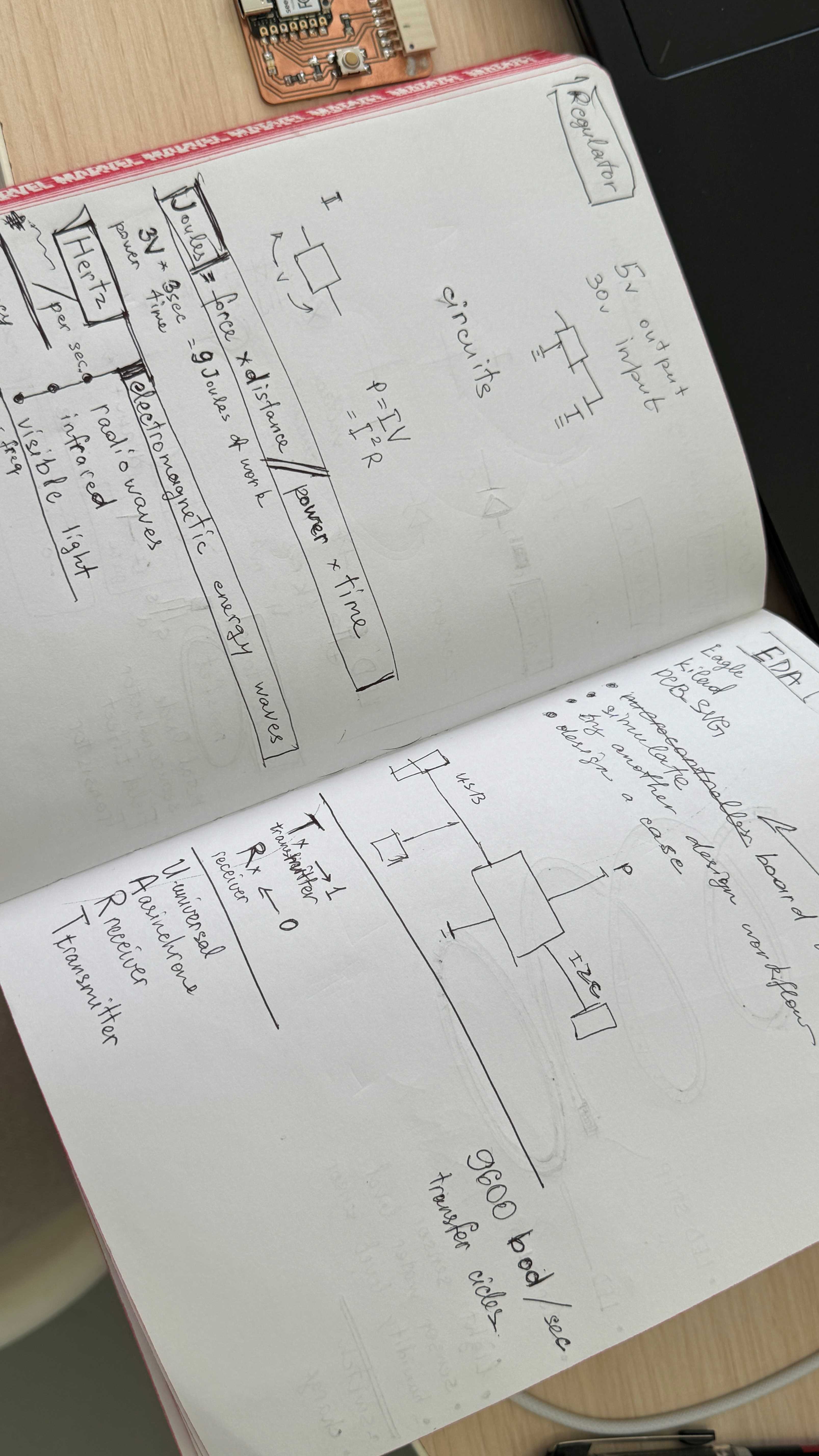
This week I am going to deep into electronics design and try out creating my own board with a microcontroller. After the class trying to understand all basics.
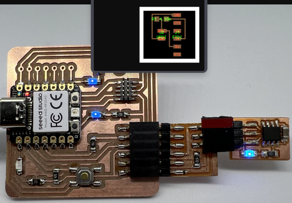
Heroshots of this week
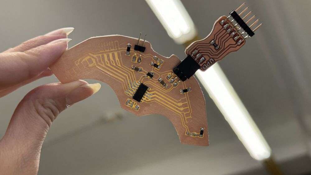
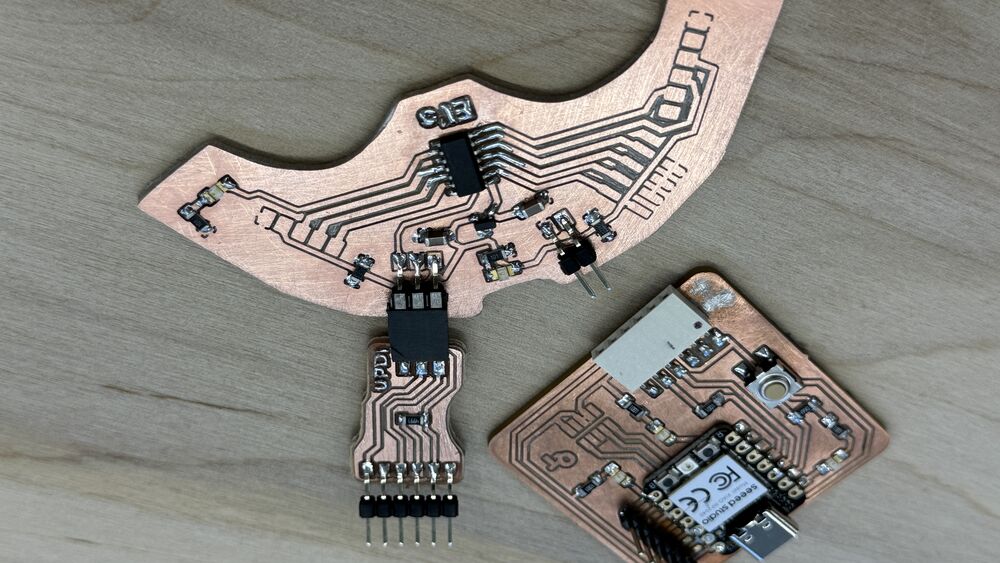
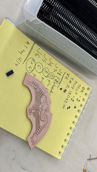
ATtiny1614 board and UPDI convertor
EDA - KiCad
- install KiCad
- install Fab lab’s component library for KiCad. KiCad Fab library
- set
fab.kicad_symas symbol library andfab.prettyas footprint library - set footprints for all the components
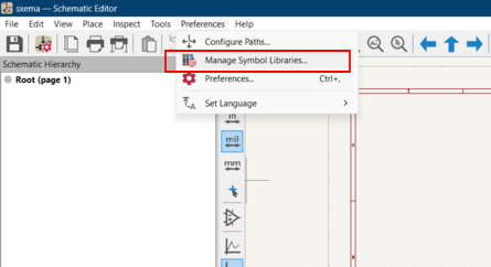
Adding footprint library of Fab.lbr into KiCad. Preferences > Manage Symbol Libraries
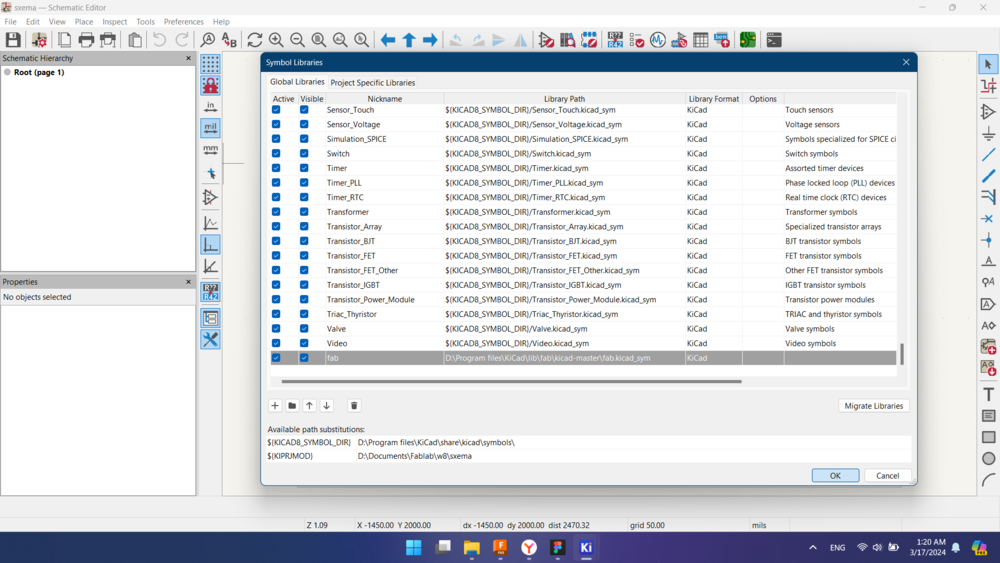
Add downloaded Fab.lbr folder by clicking on folder button.
Now in the library of symbols appeared folder “fab”. But the footprints are not added.
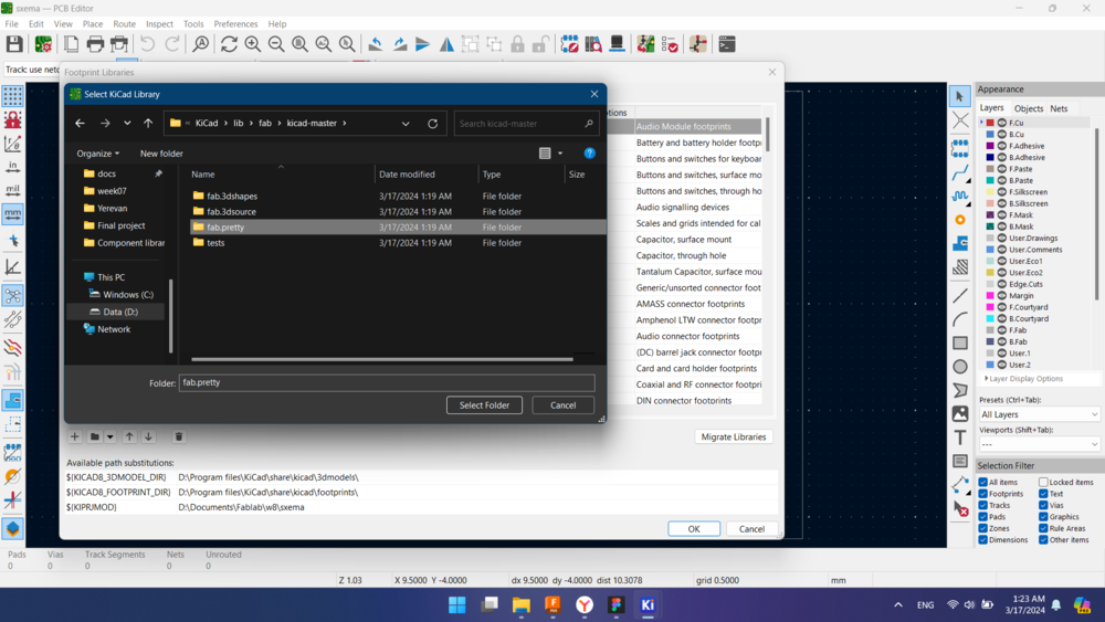
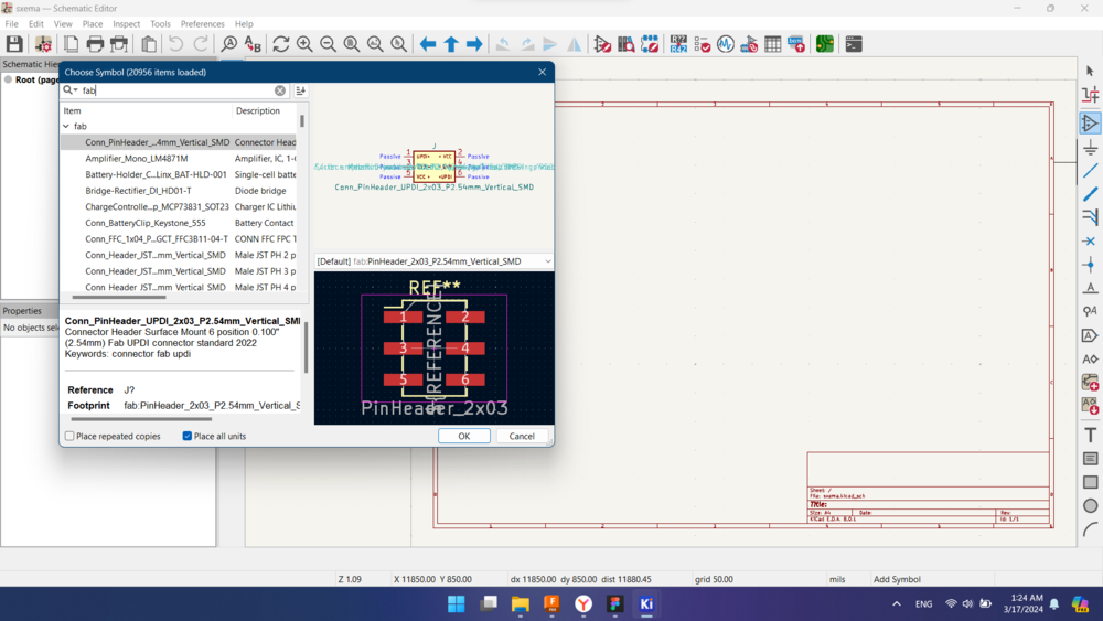
After this we need to add footprint for every single component in kiCAD’s PCB design section. Switch to PCB design > Preferences > Manage Footprint Libraries, add fab.pretty from “fab” folder.
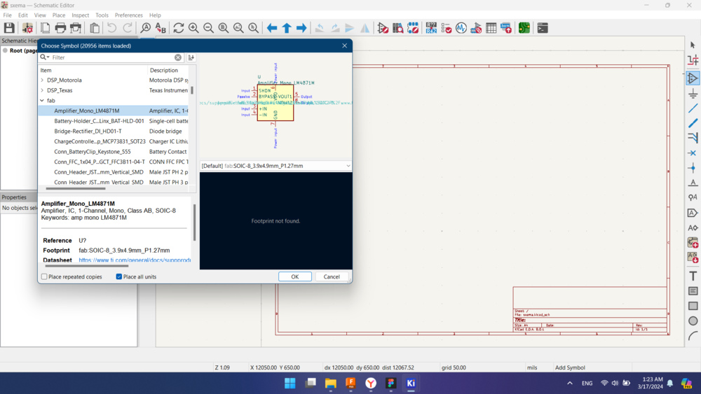
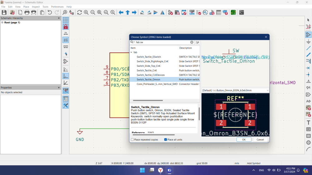
For every symbol there is a footprint, which can be found by searching in Choose symbol panel.
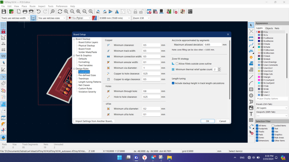
For milling in Roland SRM, we use a 1/64 mill for isolating traces, so we need to modify values accordingly for widths about 0.4 mm
QuenTorres board info


ATtiny1614
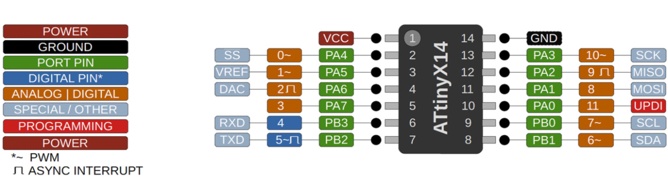
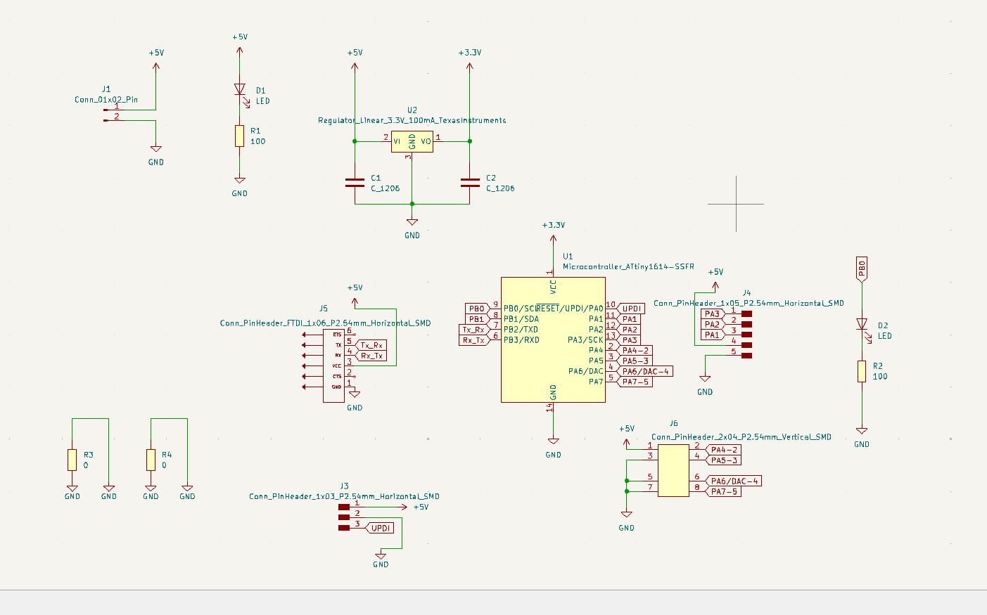
I designed a board with ATtiny1614 microcontroller. Started with inserting main components as Microcontroller, power values, voltage regulator and capacitors. A UPDI pin for programming. And some connectors related to free pins, I don’t know yet what it’s going to do.
I designed by looking at this example, and also Adrianino board and a lot of other boards to understand what they do.
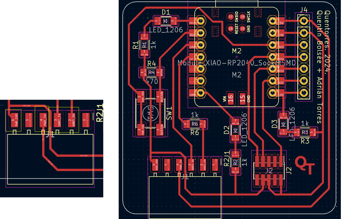
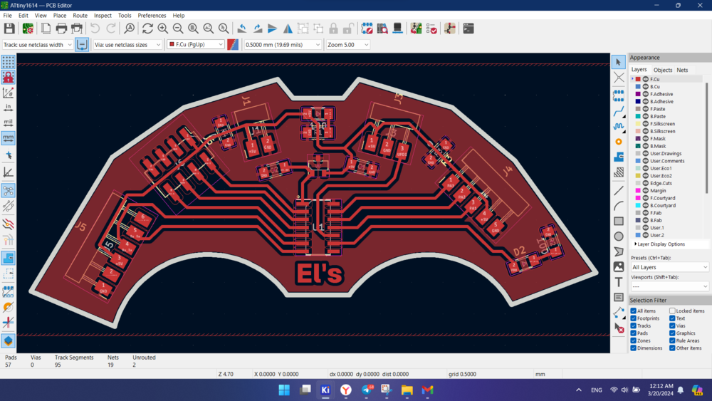
My board schematic in kicad
Here is what I made
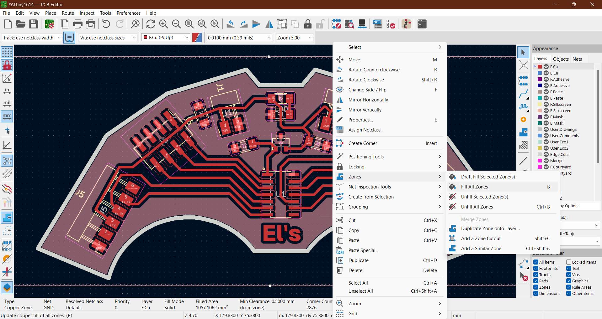
How to make shared GND (or any) filled zone.
Select contours of the board and right click > Create from Selection > Create Zone from Selection.
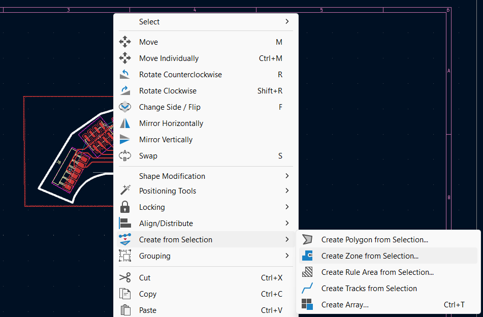
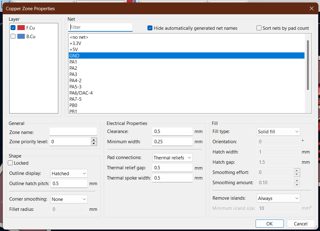
Then ctrl + B to generate the filled zone.
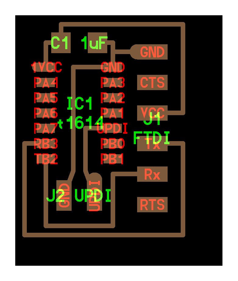
UPDI convertor
For programming I wanted to use our Quentorres board that we made in week 4. I explored the instruction in QT repository.
I start following the steps how to use QT as a programmer.
I draw the UDPI convertor scheme by looking at the picture
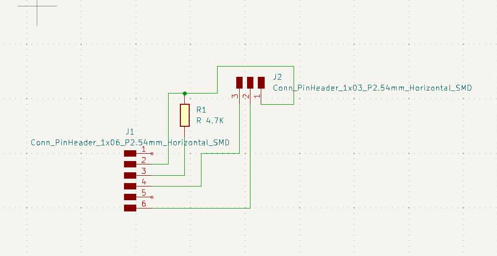
Tried to give some interesting shape in Illustrator.
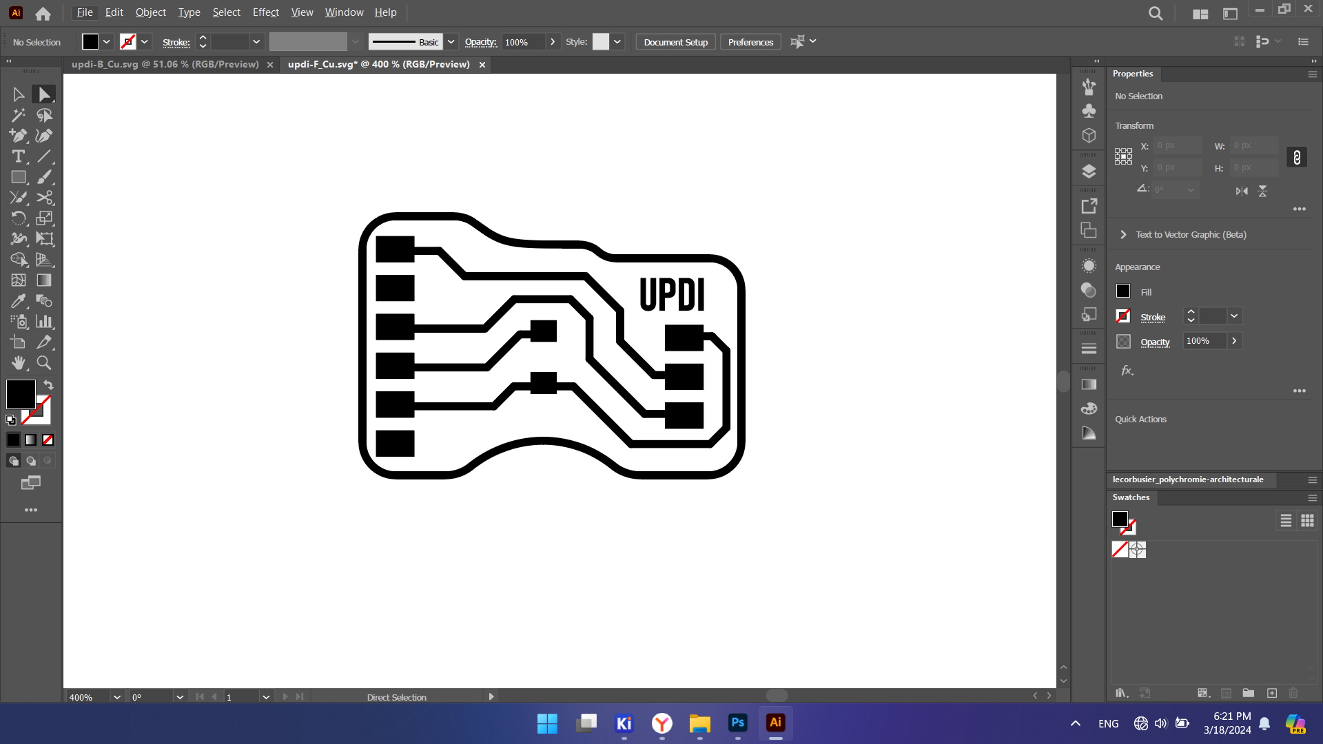
In the end exported SVG files for F.Cu and Edgecuts layers separately.
Updated 27.06.2024. Eventually, I modified PCB design because I made a mistake. Connectors that plugs into Quenterres board was mirrored so I fixed it. Now all three boards should face upside when connected.
Making PCBs
And the next steps same as sooner
- generating G-code with Mods
- milling the board
- soldering components
Programming
Steps I followed from instruction Quentorres repo.
- Reset Quentorres Board. Hold B button and then press R.
- load the uf2 file on the reset disk
- connect boards and open Arduino
- choose ATtiny1614 board and select rigth port.
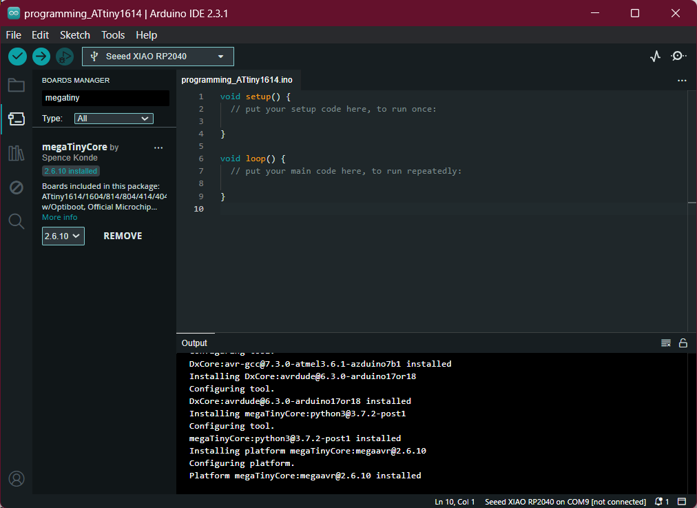
- upload ATtiny library and install MegaTinyCore.
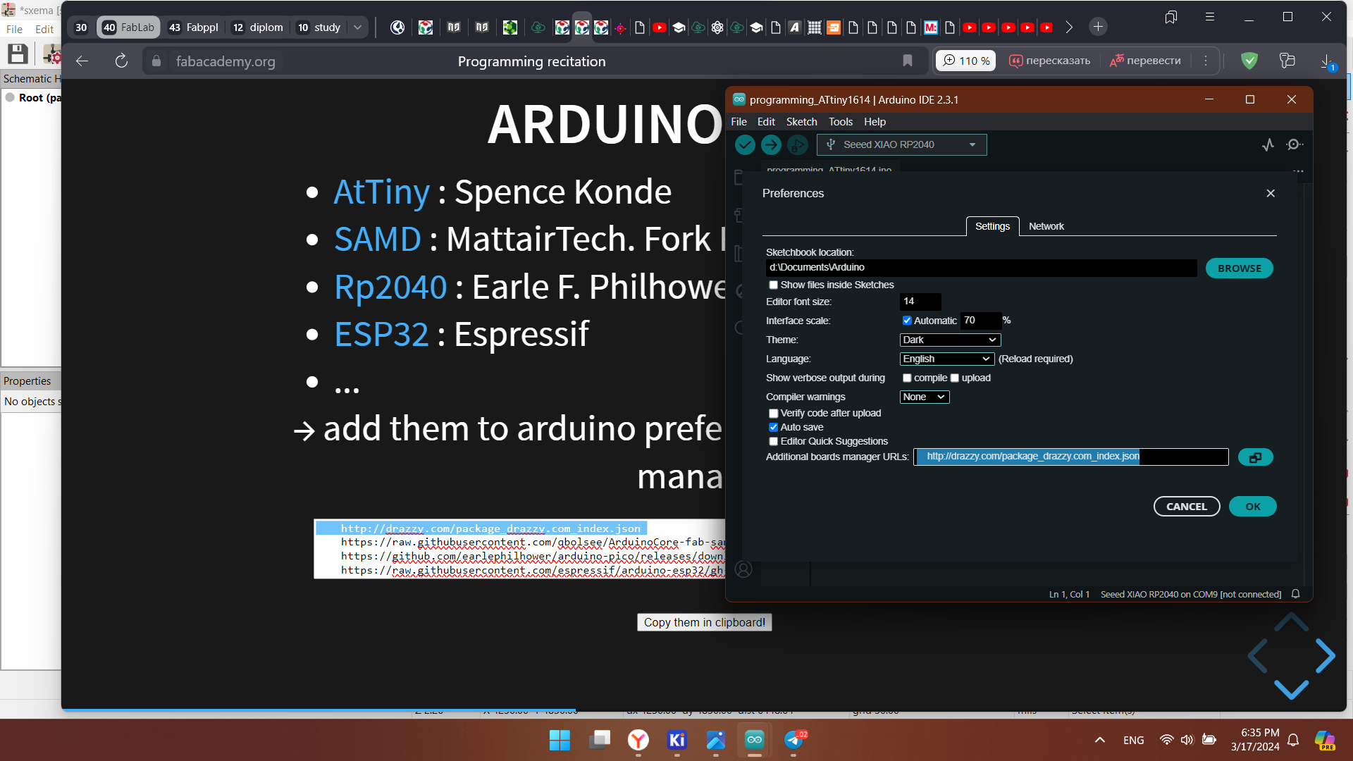
URL: http://drazzy.com/package_drazzy.com_index.json package for AtTiny boards needs to be inserted to the Additional boards manager. File > Preferences > past URL in additional boards manager section.
Install megaTinyCore in Boards Manager
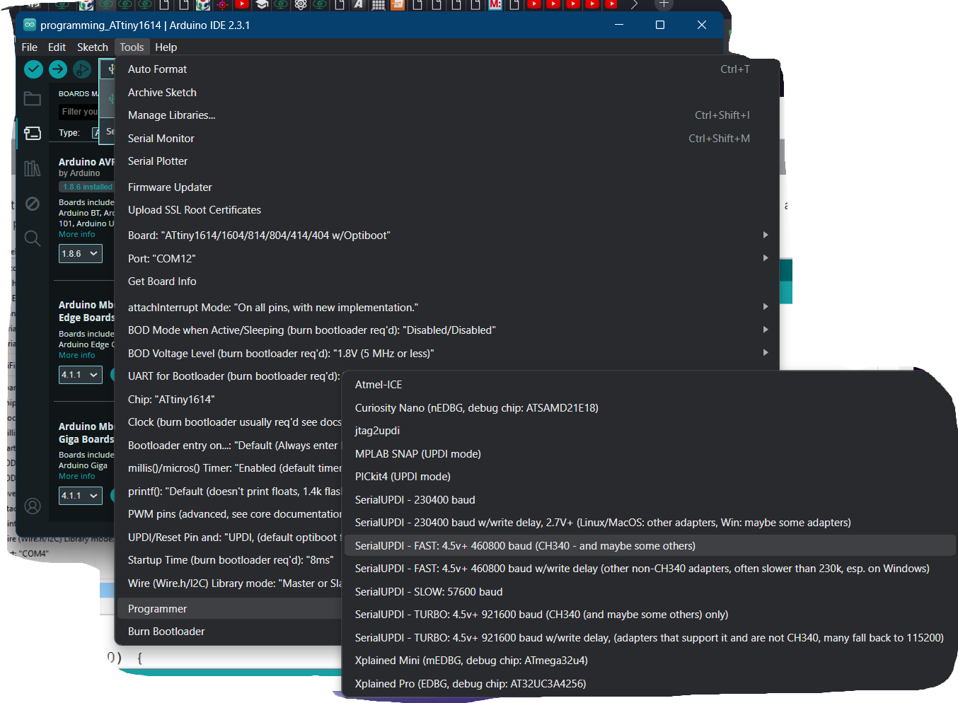
For programming AtTiny using Quentorres as a programmer, choose AtTiny1614 as a board and select the port. Choose 460800 baud how is shown in the image. Sketches must be uploaded this way Sketch > Upload Using programmer.
I used a blink program from examples, defined the LED pin
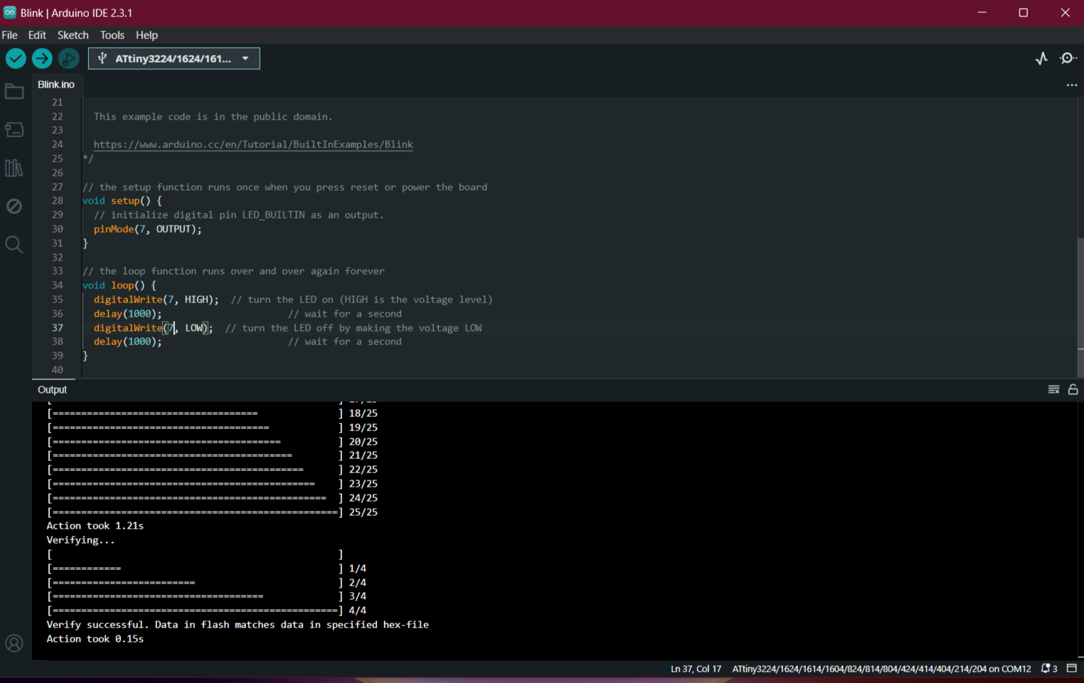
interaction with microcontroller succeed.
Group assignment
Tasks
- Use the test equipment in your lab to observe the operation of a microcontroller circuit board:
- Send a PCB out to a board house
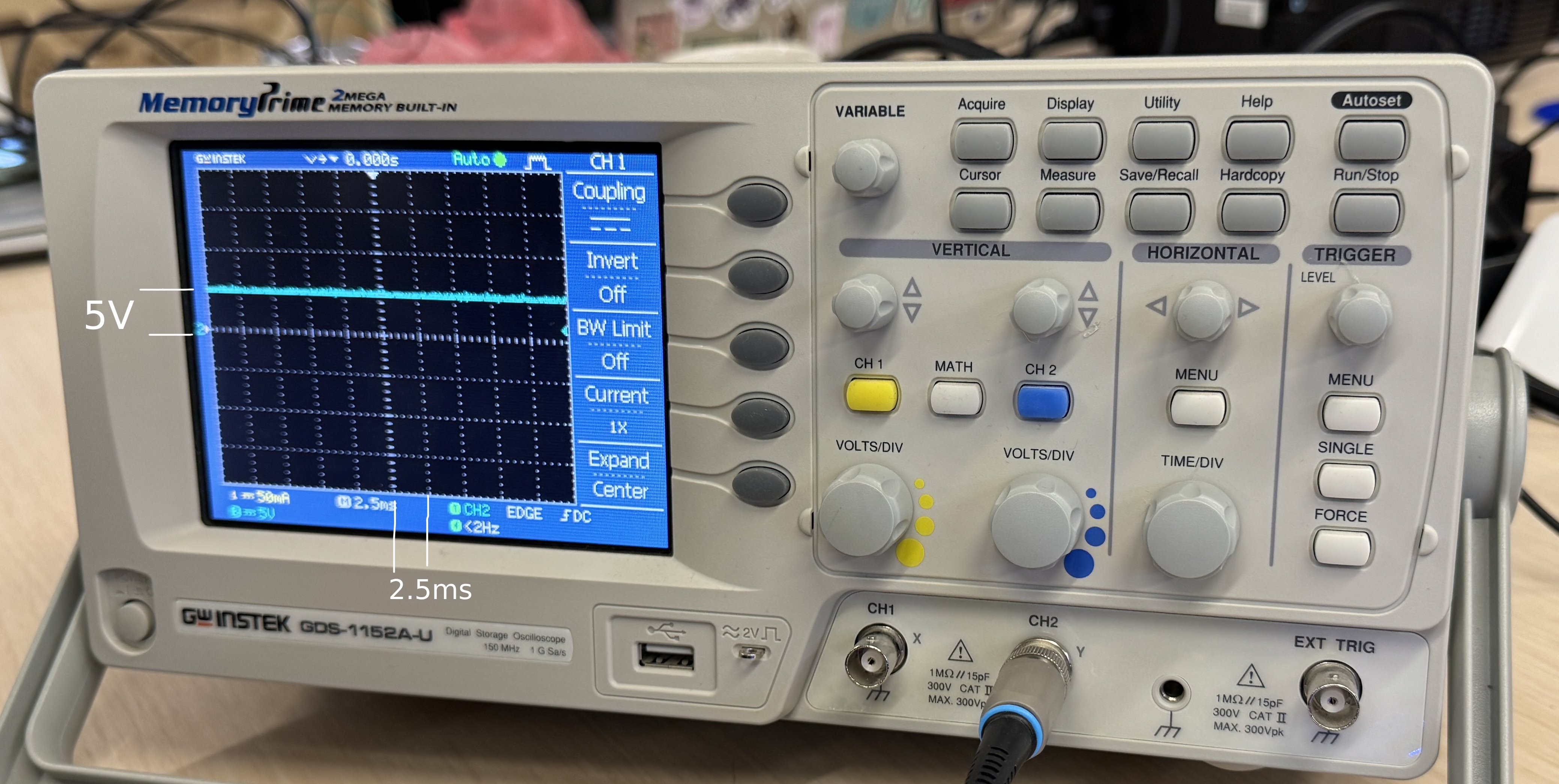
Test 1. Observe the voltage
First we measured voltages on the board. to check 5V and 3.3V flows.
Measuring the flow on 5V trace.
Test 2. Toggle pin
A. Digital pin. Let one of the pins to toggle by giving it HIGH and LOW pinModes. And then measure the pulse with oscilloscope.
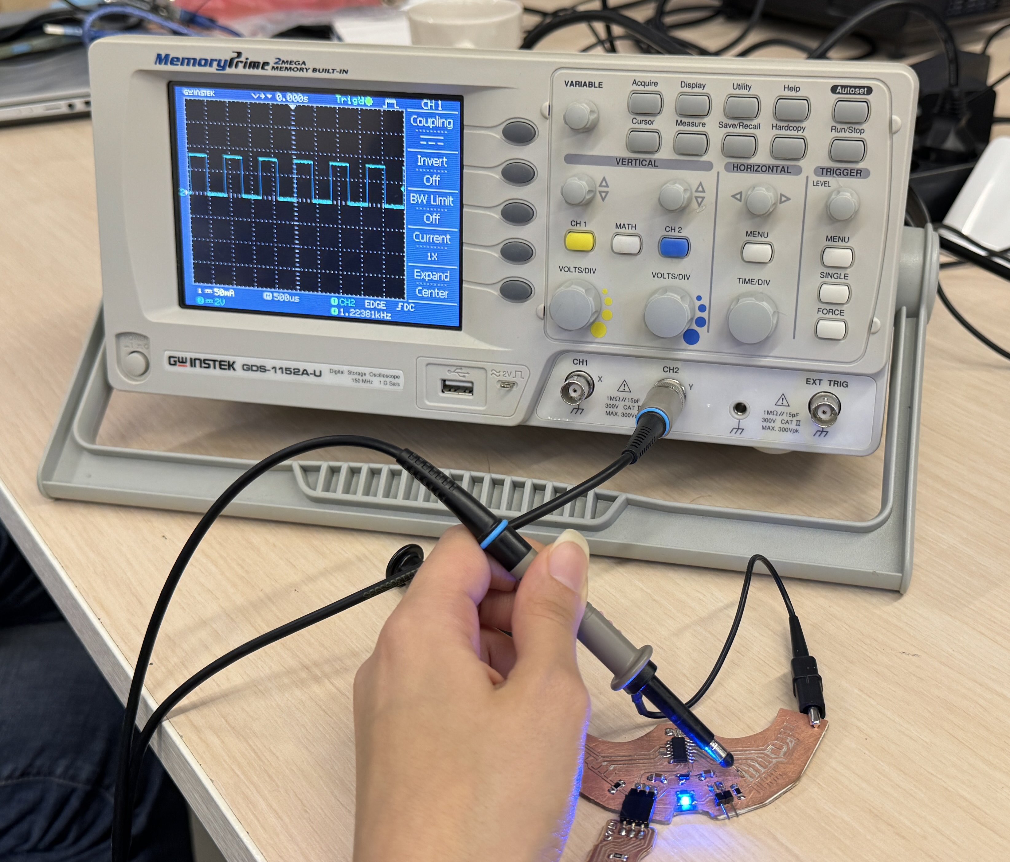
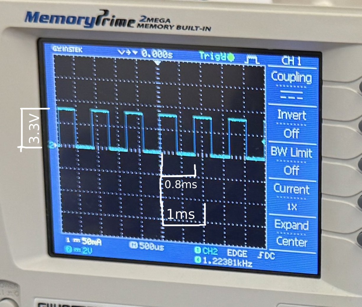
It shows on the screen 1.22381kHz. It is a frequency that the microcontroller sends information per second ~1.2K bits.
Code for toggle pin 1 of ATtiny1614
#define pin2 1
int value = 1;

void setup() {
pinMode(pin2, OUTPUT);
}

void loop() {
value = 1- value;
digitalWrite(pin2,value);  // toggle pin 2
delay(50);
}
B. Analog write
Code for fading LED on pin 0
    #define pin2 0
    int value = 1;

    void setup() {
    pinMode(pin2, OUTPUT);
    }

    void loop() {
    analogWrite(pin2, value);
    delay(50);
    value++;
    if(value >= 255) value = 0;
    digitalWrite(pin3, value);
    }
Conclusion
(Updated 14 June 2024) This week was very challenging for me as I was new to electronics and trying to make a board without fully understanding the purpose of each pin on the microcontrollers. However, after I was pleased to discover that each pin can be used for both analog and digital purposes on AtTiny1614, and we were even able to integrate in-system resistors using pull-up commands. Overall, the AtTiny board has been a great tool for me, and I have been able to use it for many weeks now. I even did a mistake and wasted important pins by connecting the Serial Data and Clock pins to the LED, as well as leaving one pin unconnected, but after these mistakes were not a big deal because we were able to identify any pin as either SDA or SCL. I am grateful that I followed Adrian’s instructions to create the UPDI connector board for the programmer, which has also been useful for our group, and served many weeks in easily programming the ATtiny using the Quentorres board.
Source files
KiCad files and svg files: