Week 13. Networking and communications
Group assignment
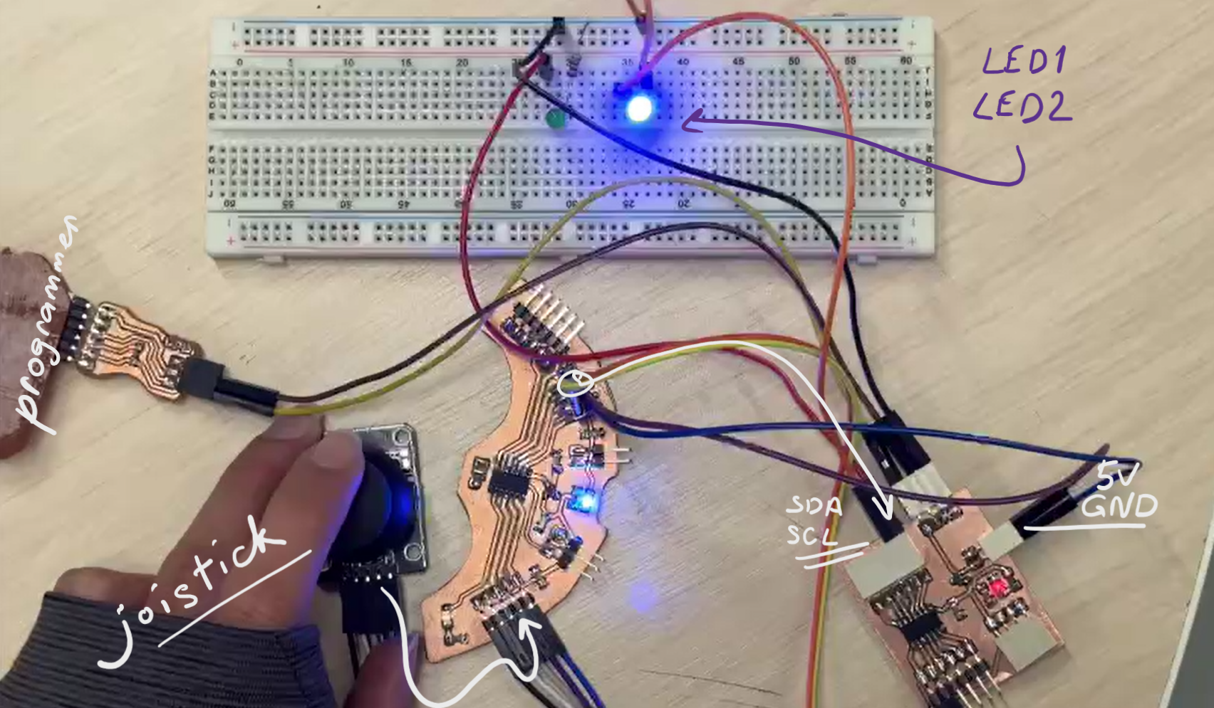
For group assignment we tried I2C communication interface between our boards.
We used
- ATtiny1614 boards
- UPDI programmer with RP2040
- Joystick
- 2 LEDs
#include <SoftwareWire.h>
const int sda=0, scl=1;  // replaced sda and scl pins on board
SoftwareWire Wire(sda,scl);
#include <hd44780.h>
#include <hd44780ioClass/hd44780_I2Cexp.h>

#define SW 10  // Joystick  pins
#define VRY 9
#define VRX 8

int SwState = 0; // joystick state
int Xposition = 0;
int Yposition = 0;

void setup() {
Wire.begin();
Serial.begin(9600);
pinMode(sda, INPUT_PULLUP); // software level resistors for SDA SCL pins
pinMode(scl, INPUT_PULLUP);
}
void loop() {
    Xposition = analogRead(VRX);
    Yposition = analogRead(VRY);
    SwState = digitalRead(SW);
    Xposition=map(Xposition,0, 1023, -512, 512);
    Yposition=map(Yposition,0, 1023, -512, 512);
    Serial.print("x: ");
    Serial.println(Xposition);
    Serial.print("y: ");
    Serial.println(Yposition);

if (Xposition !=0 || Yposition !=0) {

    Wire.beginTransmission(0x9);
    Wire.write(Xposition);
    Wire.endTransmission();
    delay(200);

}
else {
    Wire.beginTransmission(0x9);
    Wire.write(0);
    Wire.endTransmission();
    delay(200);

}
}
As on my board I’ve not provided access to default SDA SCL pins, that’s why we needed to change these pins to 0 and 1. Included the following library for replacing the pins.
ATtiny1614 has internal pullup software resistors which we activated with INPUT_PULLUP command.
#include <Wire.h>
#define I2C_SLAVE_ADDRESS 0x9  // given address to secondary board
bool ledState;
int led1=1;
int led2=0;
byte recivedData=0;
void setup() {
pinMode(led1, OUTPUT);
pinMode(led2, OUTPUT);
Serial.begin(9600);
Wire.begin(I2C_SLAVE_ADDRESS);
Wire.onReceive(receiveEvent);
}
void loop() {
if((int)recivedData > 0) {
    digitalWrite(led1,HIGH);
    digitalWrite(led2,LOW);
} else {
    digitalWrite(led1, LOW);
    digitalWrite(led2,HIGH);
}

}
void receiveEvent(int numBytes) {
while(Wire.available()){
    recivedData=Wire.read();
    Serial.println(recivedData);
}
}
WiFi communication
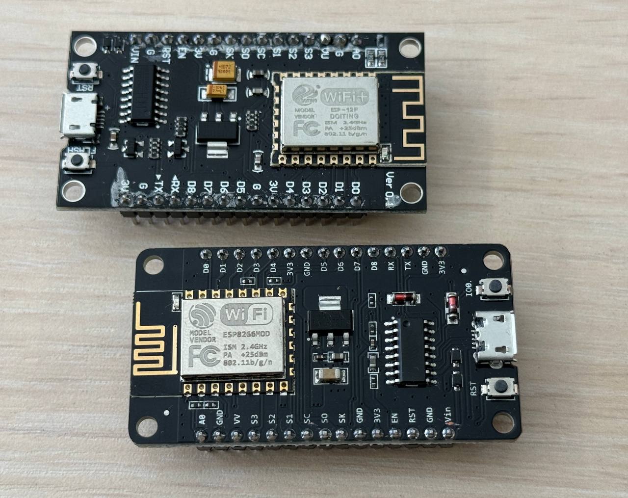
I want to set wireless communication between ESP8266 and ESP-12f.
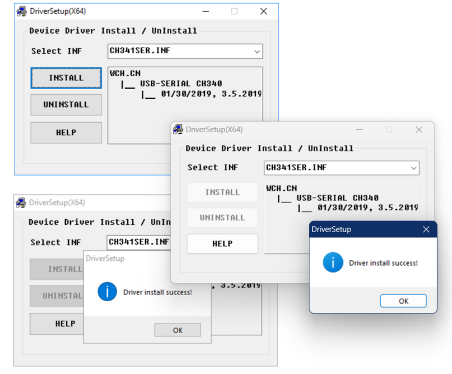
Downloaded and installed CH340 driver.
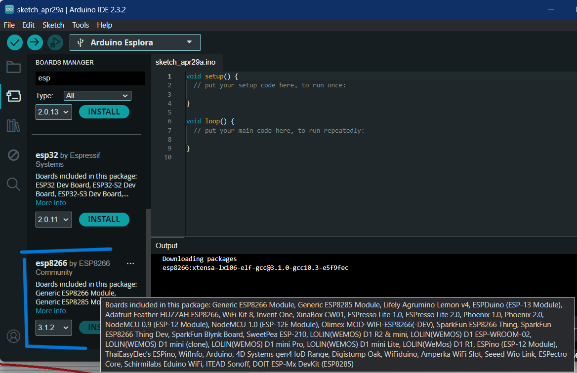
Installing Arduino library packages for these chips. for ESP-12F, ESP-12E, ESP8266
http://arduino.esp8266.com/stable/package_esp8266com_index.json
for ESP32
https://dl.espressif.com/dl/package_esp32_index.json
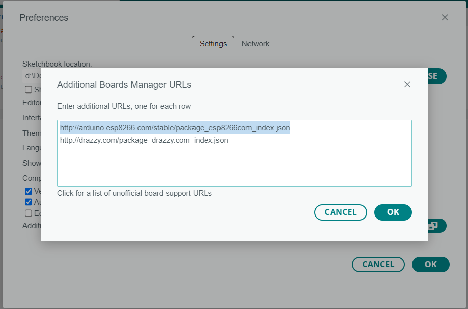
installed esp8266 boards manager package
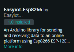
Install Easyiot-Esp8266 library
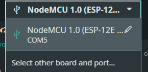
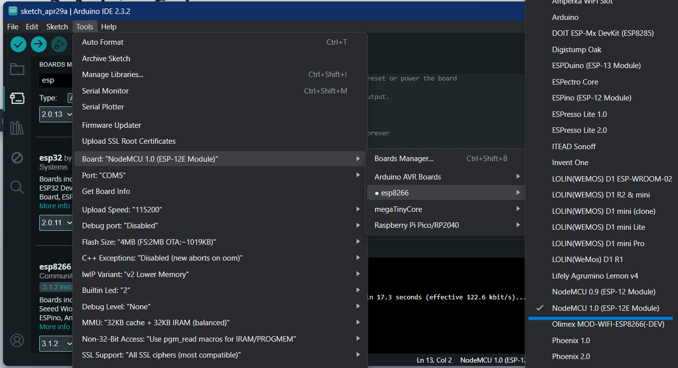
Now you should see the “ESP8266 Boards” sub-menu under Boards. Select “NodeMCU 1.0 (ESP-12E Module)” (it works for both ESP-12E and ESP-12F).
#include <ESP8266WiFi.h>
#include "ESPAsyncWebServer.h"

#include <Wire.h>


// Set your access point network credentials
const char* ssid = "ESP8266-Access-Point";
const char* password = "123456789";

// Create AsyncWebServer object on port 80
AsyncWebServer server(80);


void setup(){
// Serial port for debugging purposes
Serial.begin(115200);
Serial.println();

// Setting the ESP as an access point
Serial.print("Setting AP (Access Point)…");
// Remove the password parameter, if you want the AP (Access Point) to be open
WiFi.softAP(ssid, password);

IPAddress IP = WiFi.softAPIP();
Serial.print("AP IP address: ");
Serial.println(IP);

server.on("/hello", HTTP_GET, [](AsyncWebServerRequest *request){
    request->send_P(200, "text/html", "<p>hello</p>");
});

// Start server
server.begin();
}

void loop(){

}
#include <ESP8266WiFi.h>
#include <ESP8266HTTPClient.h>
#include <WiFiClient.h>
#include <ESP8266WiFiMulti.h>
ESP8266WiFiMulti WiFiMulti;
const char* ssid = "ESP8266-Access-Point";
const char* password = "123456789";
const char* serverName = "http://192.168.4.1/hello";
//Your IP address or domain name with URL path
#include <Wire.h>
String wifi;
unsigned long previousMillis = 0;
const long interval = 5000;
void setup() {
Serial.begin(115200);
Serial.println();
Serial.print("Connecting to ");
Serial.println(ssid);
WiFi.begin(ssid, password);
while (WiFi.status() != WL_CONNECTED) {
delay(500);
Serial.print(".");
}
Serial.println("");
Serial.println("Connected to WiFi");
}
void loop() {
unsigned long currentMillis = millis();
if(currentMillis - previousMillis >= interval) {
// Check WiFi connection status
if ((WiFiMulti.run() == WL_CONNECTED)) {
wifi = httpGETRequest(serverName);
Serial.println(wifi);
// save the last HTTP GET Request
previousMillis = currentMillis;
}
else {
Serial.println("WiFi Disconnected");
}
}
}
String httpGETRequest(const char* serverName) {
WiFiClient client;
HTTPClient http;
// Your IP address with path or Domain name with URL path
http.begin(client, serverName);
// Send HTTP POST request
int httpResponseCode = http.GET();
String payload = "--";
if (httpResponseCode>0) {
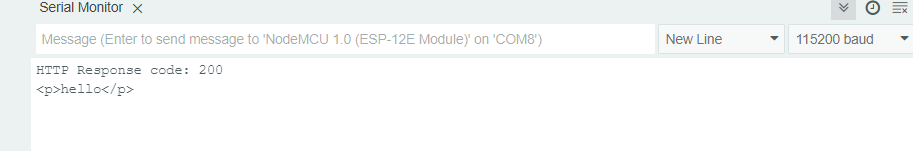
Serial.print("HTTP Response code: ");
Serial.println(httpResponseCode);
payload = http.getString();
}
else {
Serial.print("Error code: ");
Serial.println(httpResponseCode);
}
// Free resources
http.end();
return payload;
}
Wifi communication with HTTP protocol, One module is Wifi Access point, and sends hello request to server, the other module is connected to wifi and gets request from server.
UART
I tried to communicate my ATtin1614 board and the Quentorres board with RP2040 through UART protocol.
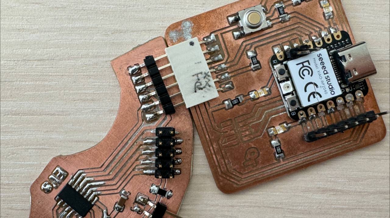
I’ve designed the ATtiny1614 board with UART connector that will provide Rx to Tx, Tx to Rx, 3.3V and GND connections.
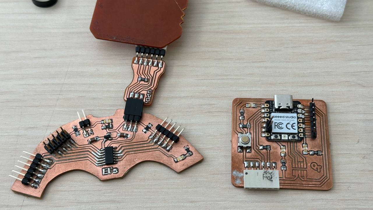
The UART connection through RxTx
Hello from ATTiny1614!
Here ATtiny1614 works as transmitter and sends a message to RP2040, which is receiving and the message is being printed by RP2040 on serial monitor.
#include <SoftwareSerial.h>
SoftwareSerial softSerial(4, 5); // rx tx

void setup()
{
softSerial.begin(9600);
}
void loop()
{
softSerial.println("Hello from ATtiny1614!");
delay(1000);
softSerial.print(0);
delay(1000);
}
#include<SoftwareSerial.h>

SoftwareSerial softSerial(29, 28); //rx tx

void setup() {
softSerial.begin(9600);
Serial.begin(9600);

}

void loop() {
if (softSerial.available())
{
    Serial.write(softSerial.read());

}
}
Turn LED on/off
Here I make LED blink on RP2040 which is received command from ATtiny1614 through serial communication.
#include <SoftwareSerial.h>
SoftwareSerial softSerial(4, 5);

void setup()
{
softSerial.begin(9600);
Serial.begin(9600);
}
void loop()
{
softSerial.print(1);
Serial.print(1);
delay(1000);
softSerial.print(0);
Serial.print(0);
delay(1000);
}
#include<SoftwareSerial.h>

SoftwareSerial softSerial(29, 28); //rx tx

char number  = ' ';
int LED = 26;

void setup() {
softSerial.begin(9600);
Serial.begin(9600);
pinMode(LED, OUTPUT);
}

void loop() {
    if (softSerial.available())
    {
    char number = softSerial.read();
    if (number == '0') {
    digitalWrite(LED, LOW);
    }
    if (number =='1'){
    digitalWrite(LED, HIGH);
    }
    Serial.print(number);
}
}
Conclusion
This week was challenging as usual electronics week for me. In group assignment we tried I2C communication. For individual assignment I tried communication over WiFi, using two ESP-12F and UART communication between Quentorres board with RP2040 and my board with ATtiny1614. I made them send and receive simple Hello messages and I’ve learnt some basics about different communication interfaces.