Week 12. Molding and Casting
Molding and Casting week introduction
What I learned this week is a lot about molding and casting mostly with cast iron, also with other metals and plastic polymers. Thanks to Ashot, our Fab lab continuing student, who perfectly completed this week’s instructing for us and hosted us few days in his metal factory where we made our projects with iron casting technology. We gained a lot of knowledge and new opportunities to fabricate our projects.
Group assignment
For group assignment Ashot held a presentation where he showed in detail how cast iron casting is carried out, what is included in the composition of metals and the percentage ratio good for casting and product safety. We also conducted an experiment casting iron into a 3D-printed object. The purpose of the test was to make PLA melt when filling the mold with iron foundry, which is replacing the 3D object’s space in a casting flask filled with sand. And that way we made a statue of Moai casted with cast iron.
laboratory analyses
Additionally, we were taken to a tour in the laboratory by Ashot. He showed us how they diagnose the material which is being used in the process of casting in the factory.
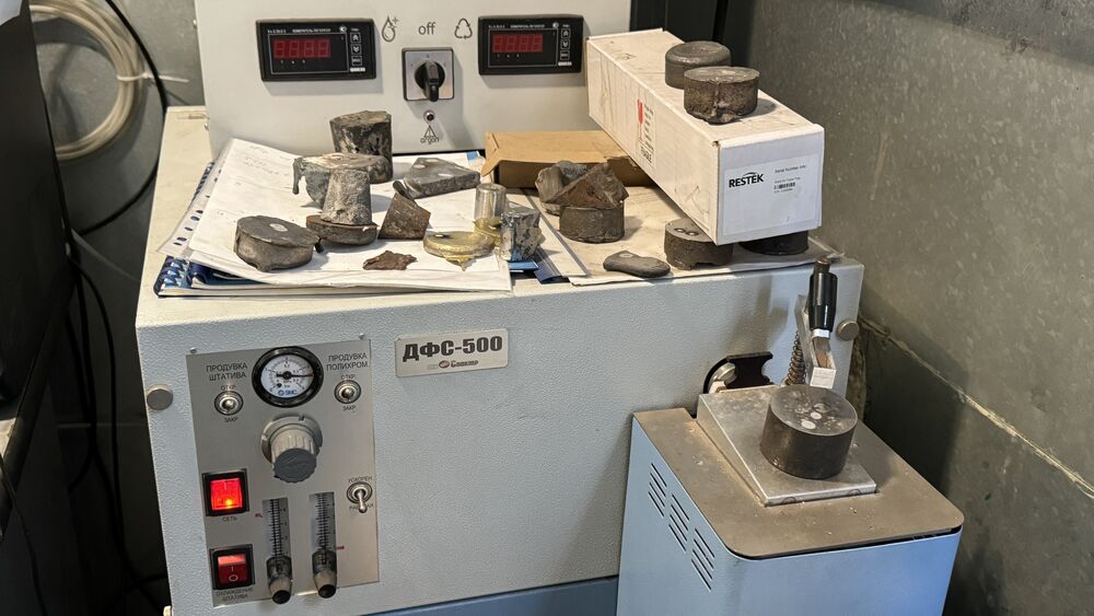
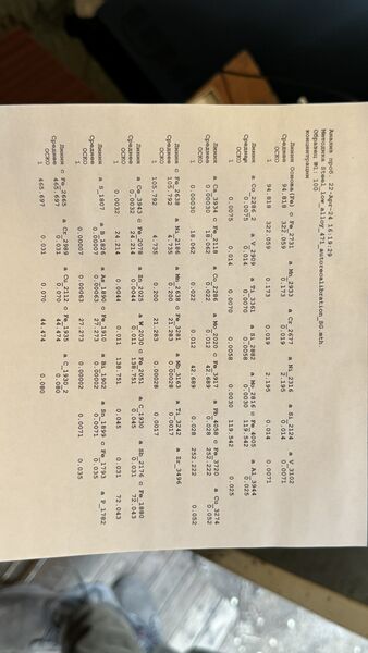
The machine is spectral analysis for metals. It works with libraries for each metal and detects the components in the metal composites.
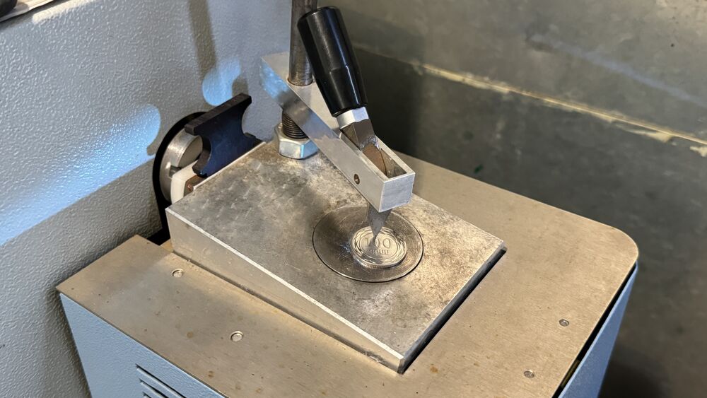
We tried out the work of the machine with a 100 Dram coin.
Each of us experienced with different materials in our group. And we’ve learnt a lot and I successfully created interesting and beautiful things.
Individual assignment: Cast iron bench
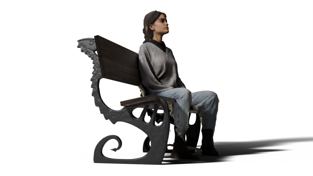
Heroshot
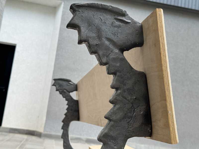
With the opportunity of using iron cast as casting material provided by our lab and Ashot’s metal factory, I decided to design and make a bench. Here are the steps of whole process.
- Design model
- Making the pattern
- CAM (milling the pattern from plywood and some 3D print parts)
- Preparing the pattern for molding (Prime and sanding)
- Making moulds
- Filling with cast iron
Design process
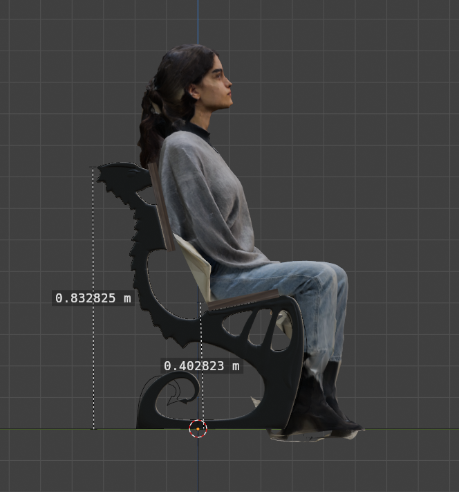
I started design and modeling of the bench in Blender. Used standard bench height of sitting platform 40cm from the ground, width 60cm, height of back 80cm from the ground, 5-15 degree angle for back, and 4-9 degree angle for the seat.
You can download 3D Model files from Sketchfab.
At first I created the silhouette of bench on a plane with adding vertices. Then used Modifiers to form the 3D model.
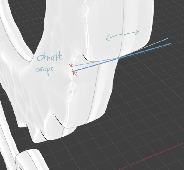
Applied modifiers and started making draft angles.
Draft angles
It’s important thing for casting to have at least minimal draft angles on the model for pulling out the pattern from the mould without destroying it.
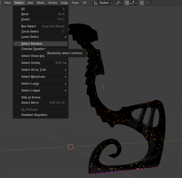
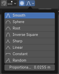
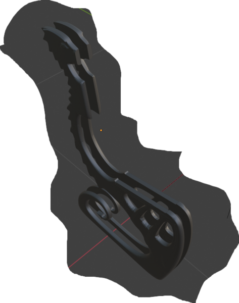
Later I was offered by Ashot to add relief on the surface. For that the fastest way I could think of was transforming randomly selected vertices. I moved inside vertices in proportional editing mode.
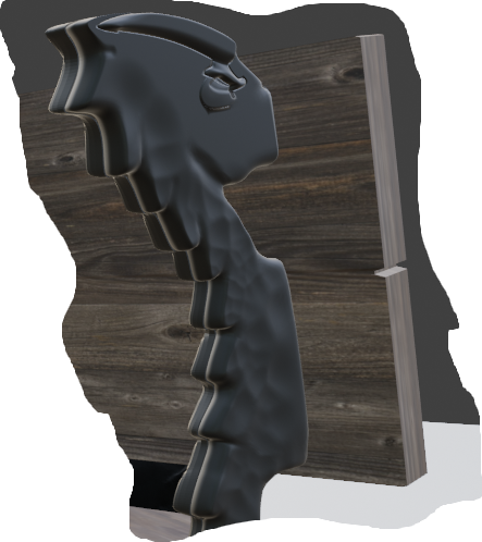 Separated the model into two parts for molding. Exported parts as STL from Blender.
CAM
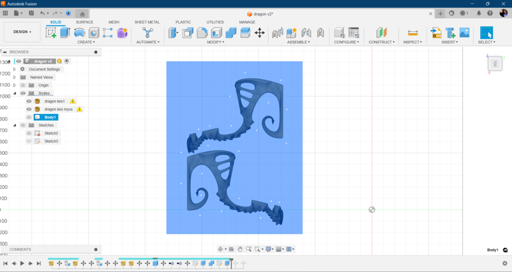
Manufacturing in Fusion 360.
Inserted STL files in Fusion 360. Insert > insert mesh.
Then arranged on the ground and made them fit into ShopBot’s bed sizes. Made the box same sized and width as the plywood I am going to cut. Then arranged holes for fixing material on the bed, avoiding screws for being interact with models.
As some parts were thicker then my material so I used separate parts of plywood for thickening. Added boxes and joined them.
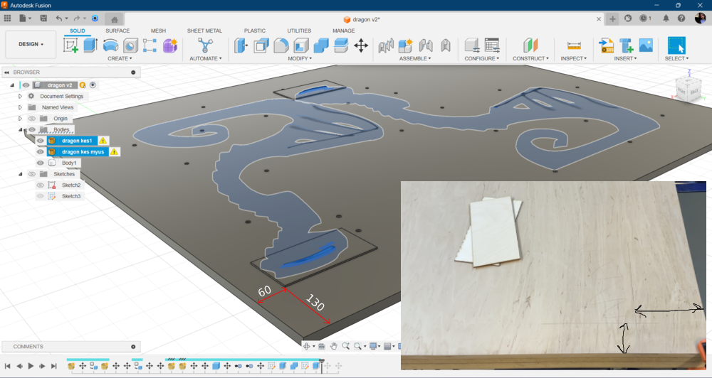
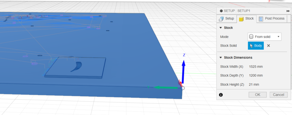
In this case in manufacturing setup I’m going to use stock mode from solid and select the joined body.
Milling toolpaths
here are steps of milling toolpath and generated g-codes
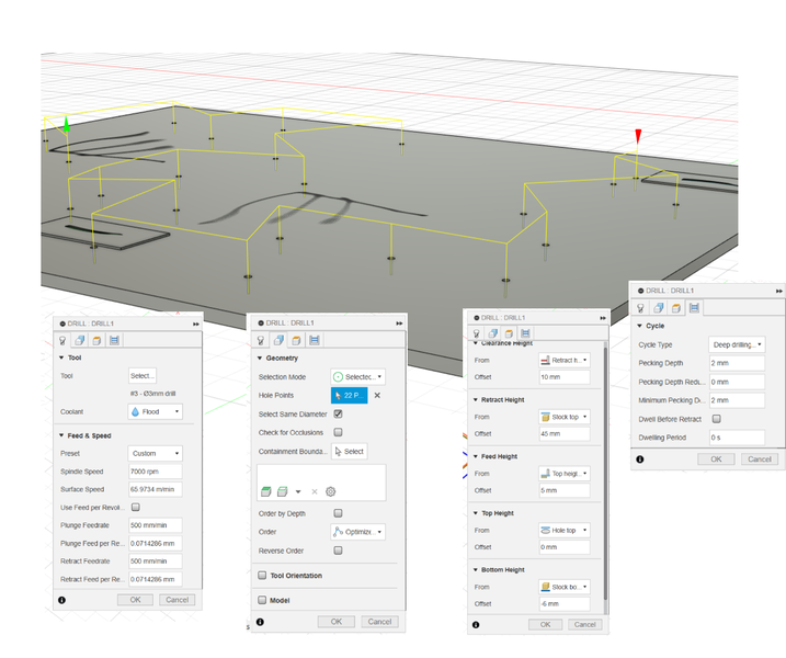
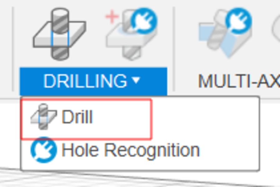 For first step is good to drill holes to fix the plywood on the machine’s bed. Drilling with machine using the generated g code provides the opportunity to make holes in right places by avoiding model parts. It took about 20 minutes.
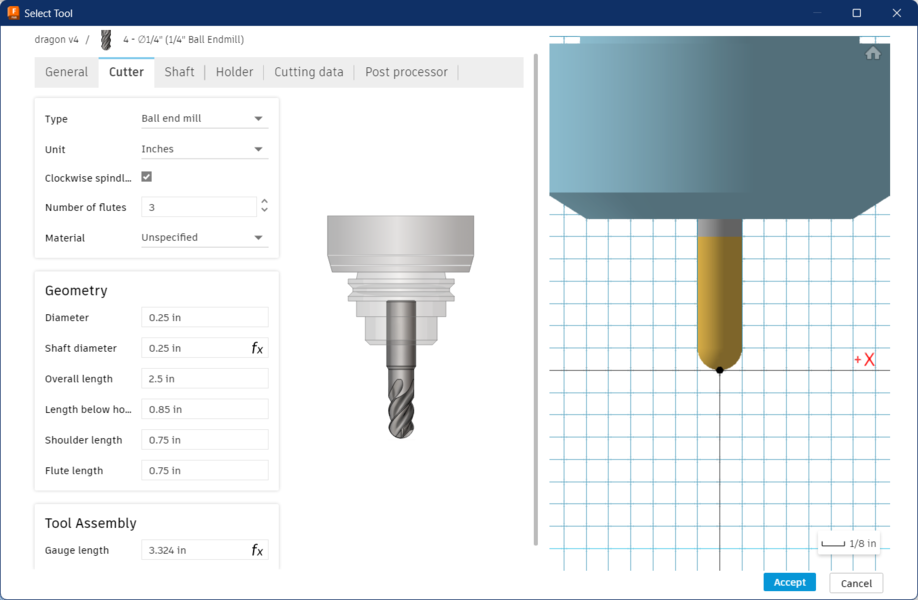
toolpath for drilling with 3mm diameter drill I used.
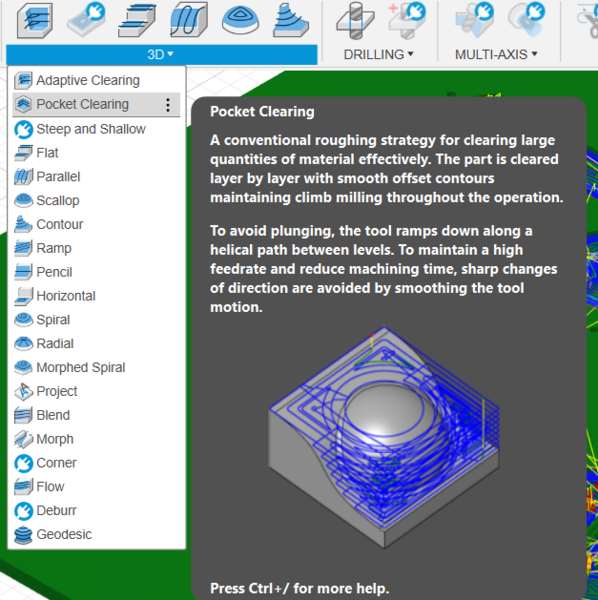
Roughing is first step of clearing the material and making approximate contours which is pending final more precise clearing for next step. It can be done with bigger diameter tools for effective process.
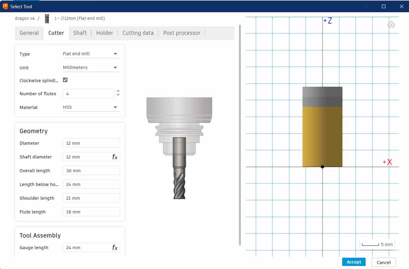
Tool preferences for 3D pocket I used 12 mm diameter flat end mill.
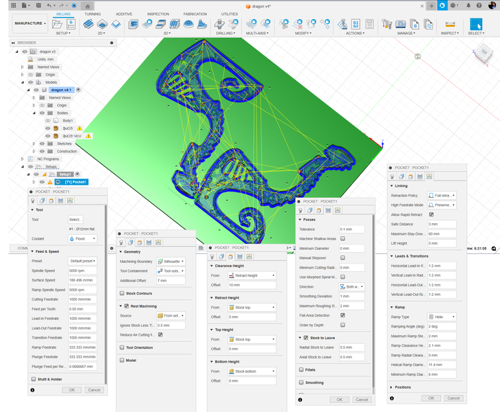
3D pocket toolpath preferences
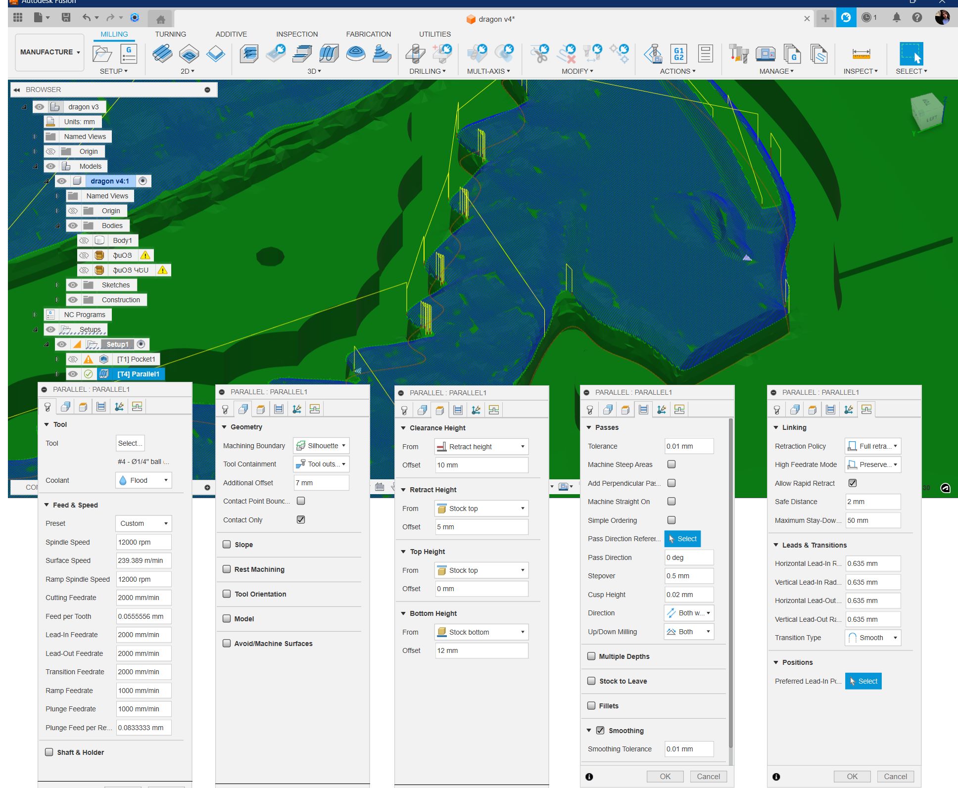
For finishing used toolpaths Parallel and Contour
Parallel clearing first, to smooth the reliefs.
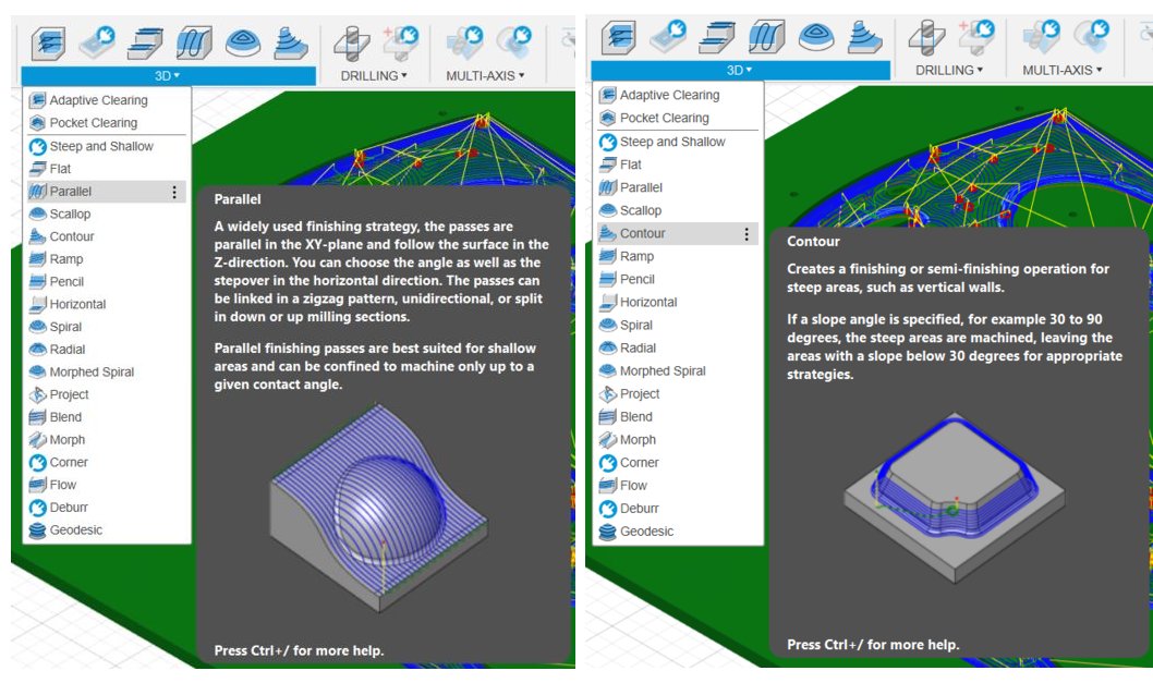
6.35 mm diameter ball end mill for both finishing tools.
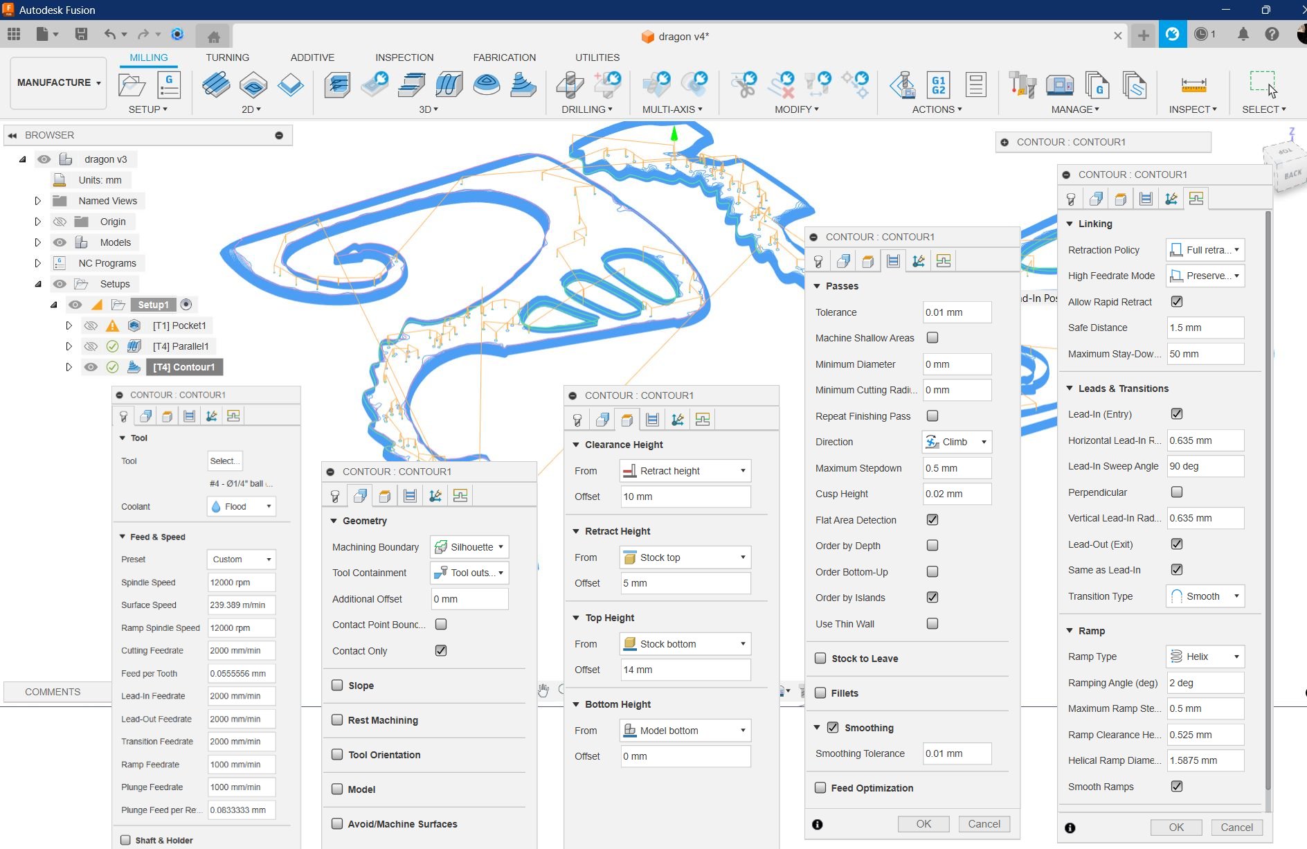
Contours
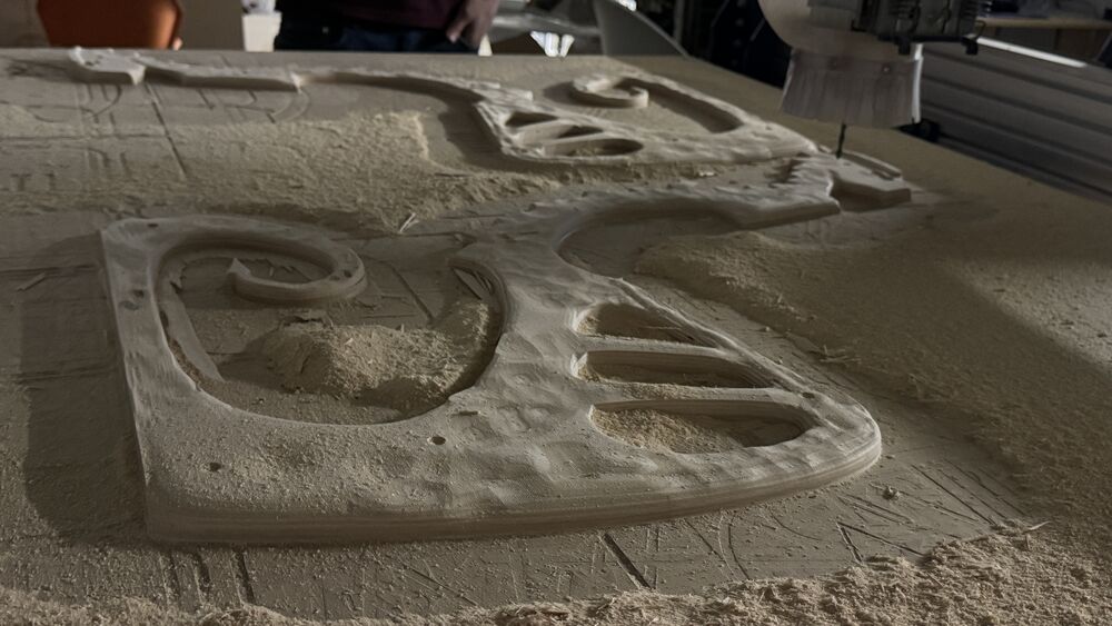
Milling the Pattern
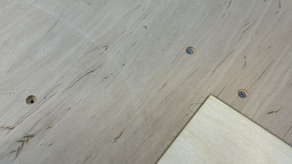
Making ready the bed with extended parts. Used two-component super glue.
Fixing with screws in the milled holes.
Next, rough clearing, Pocket process. (11 hours)
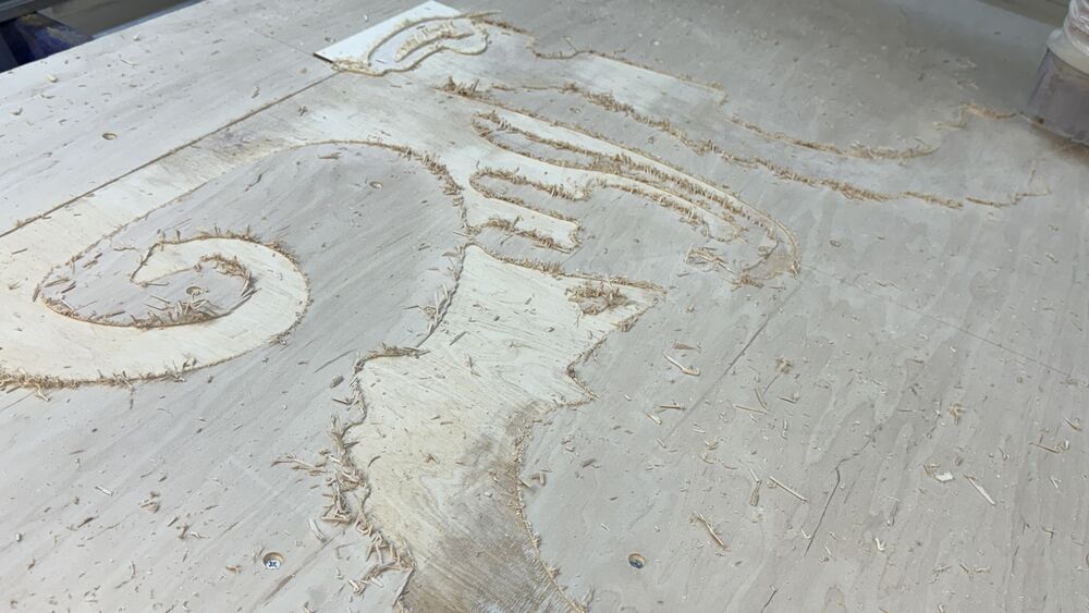
We tried to avoid the model to be screwed but it was necessary. And eventually, we fixed directly models to the bed, to reduce the shaking and vibrations.
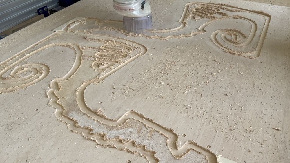
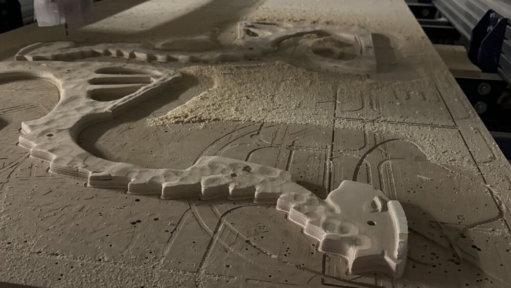
And next finishing, parallel and contour. (6 hours)
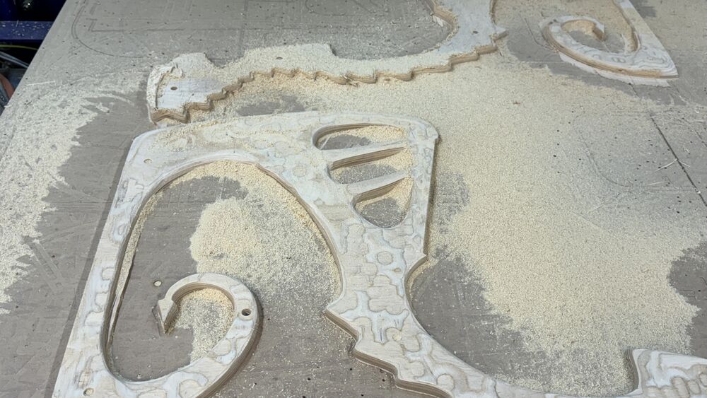
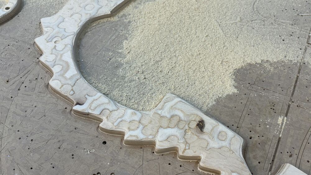
After finishing.
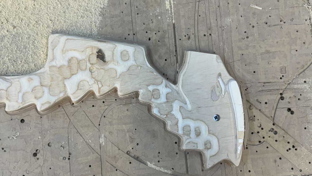
Models have to be post processed with sandpaper, primed and again sanded. For priming I used two component polyurethane primer. It’s for preventing wooden models be affected by wet.
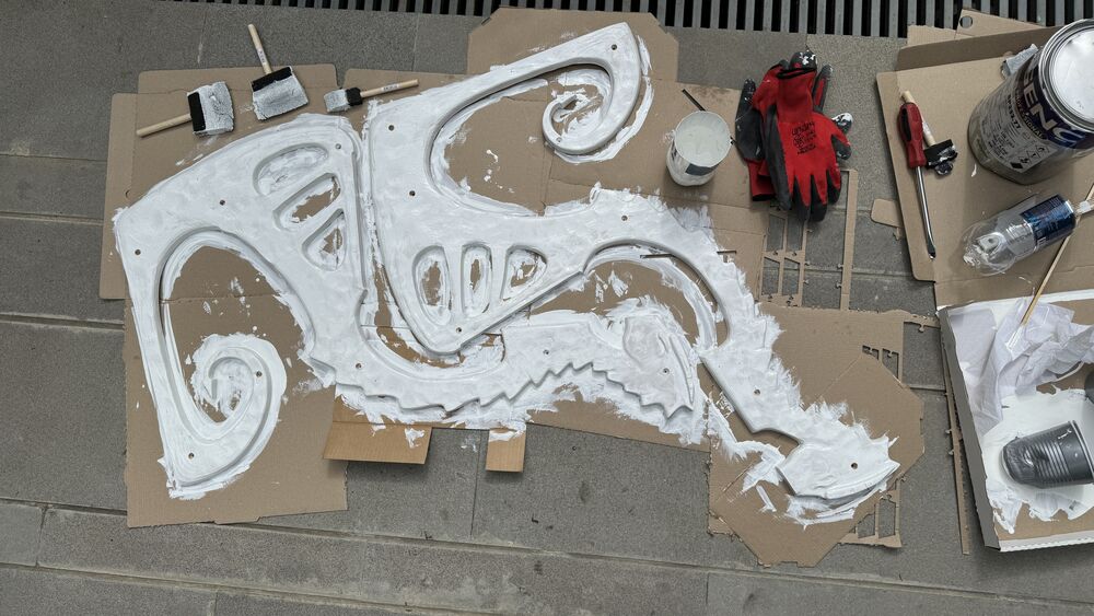
And after that good sanding helped the model to fit out easily from the mould after.
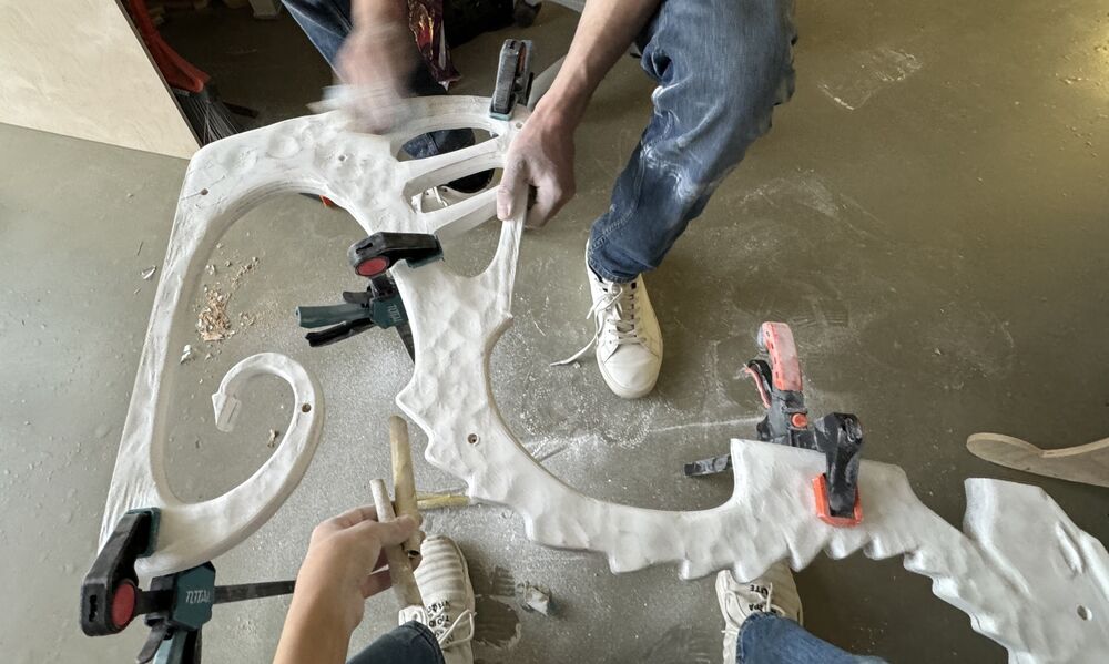
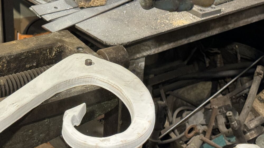
And for connecting two pars correctly, it’s needed to have guides, which we did with metallic parts and holes. One of the parts connects to the wood and the other needs to came out easily.
Mold and cast
So then we were relocated to Yerevan to continue the work in Ashot’s factory.
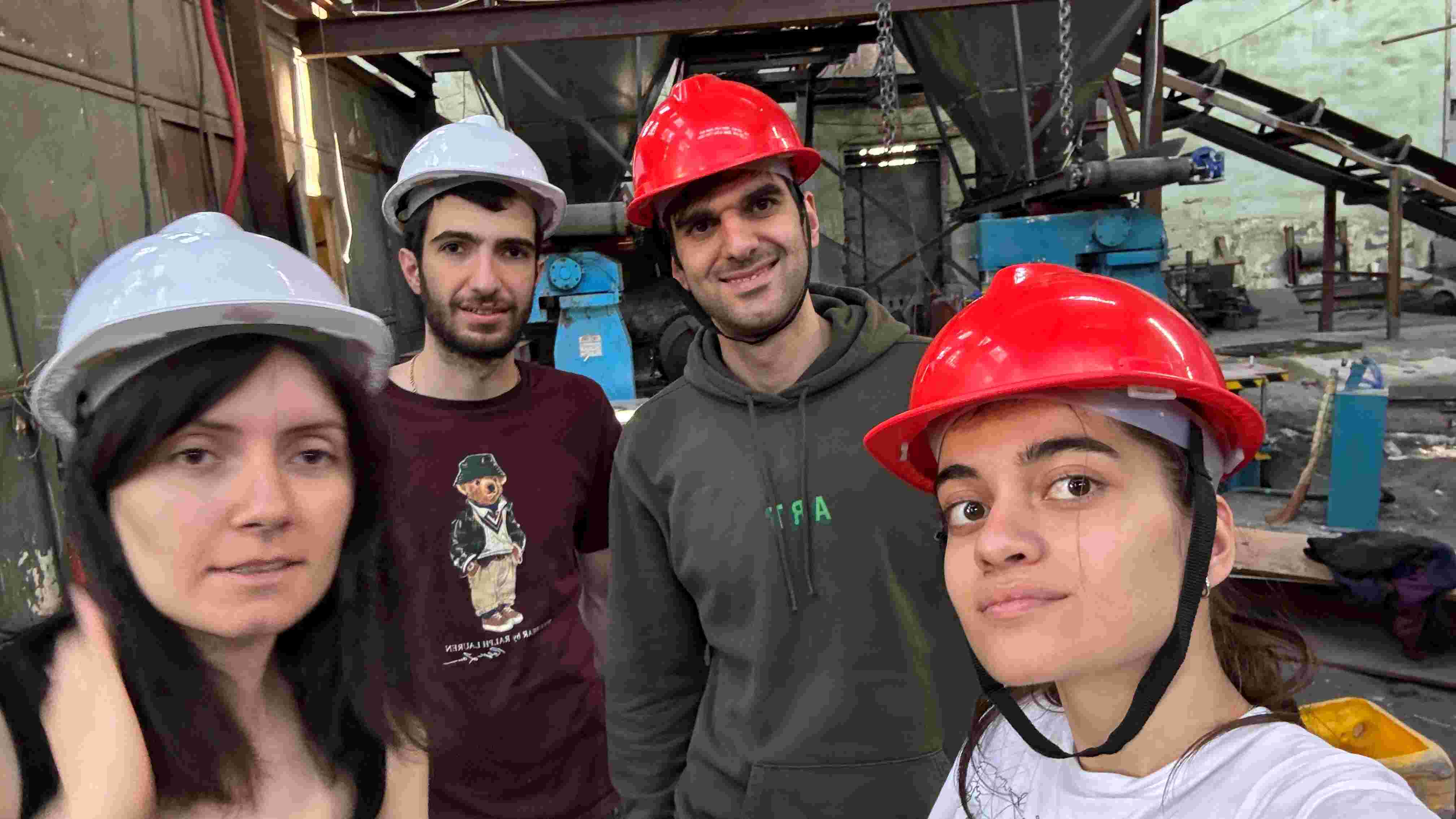
Safety in metal factory.
Here we work with molten metal and it’s temperature is more than 1000°C. It’s needed to be extremely accurate and keep a safe distance from the foundry with molten metal. Also wearing protective clothing to reduce exposure to radiant heat and molten metal splash. Also wearing helmets to be protected from falling objects.
Here is a video describing all the process of pouring cast iron in the factory and final result.
Process description
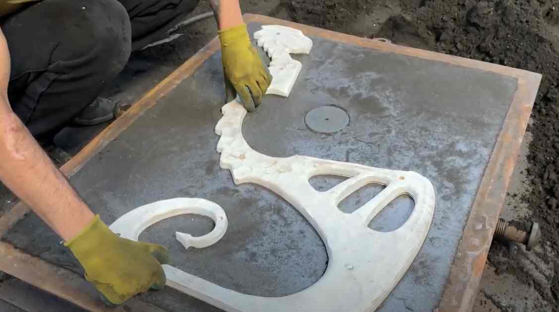
First part of pattern placed on flat surface, and flask placed on the top of it.
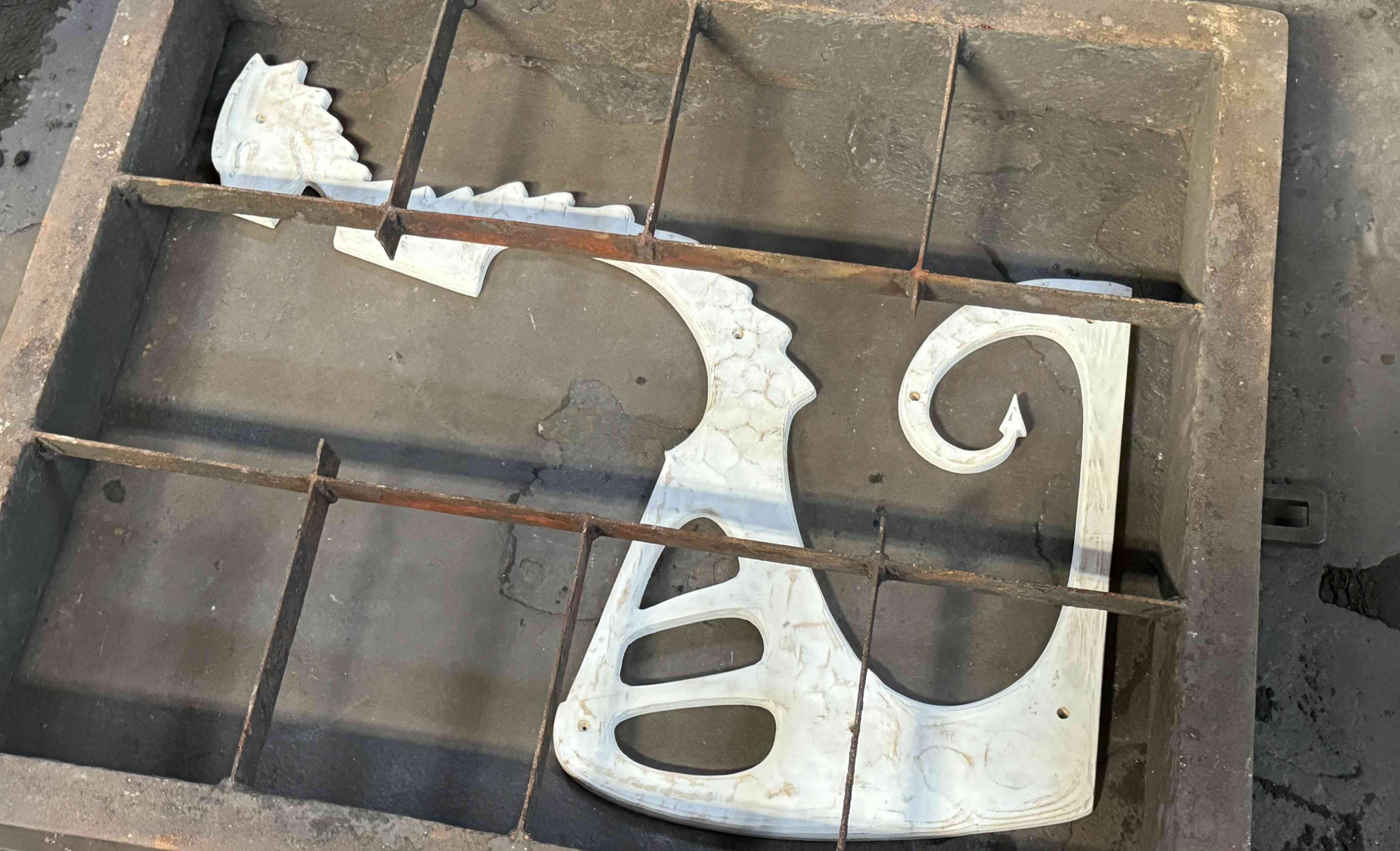
Spreading graphite on the surface between model and the sand. Also placed tube for the metal be filled in.
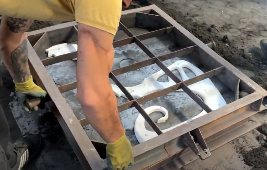
After filling the sand, they are pressing it.
Then they took up the Flask and it’s good that model slight out from it.
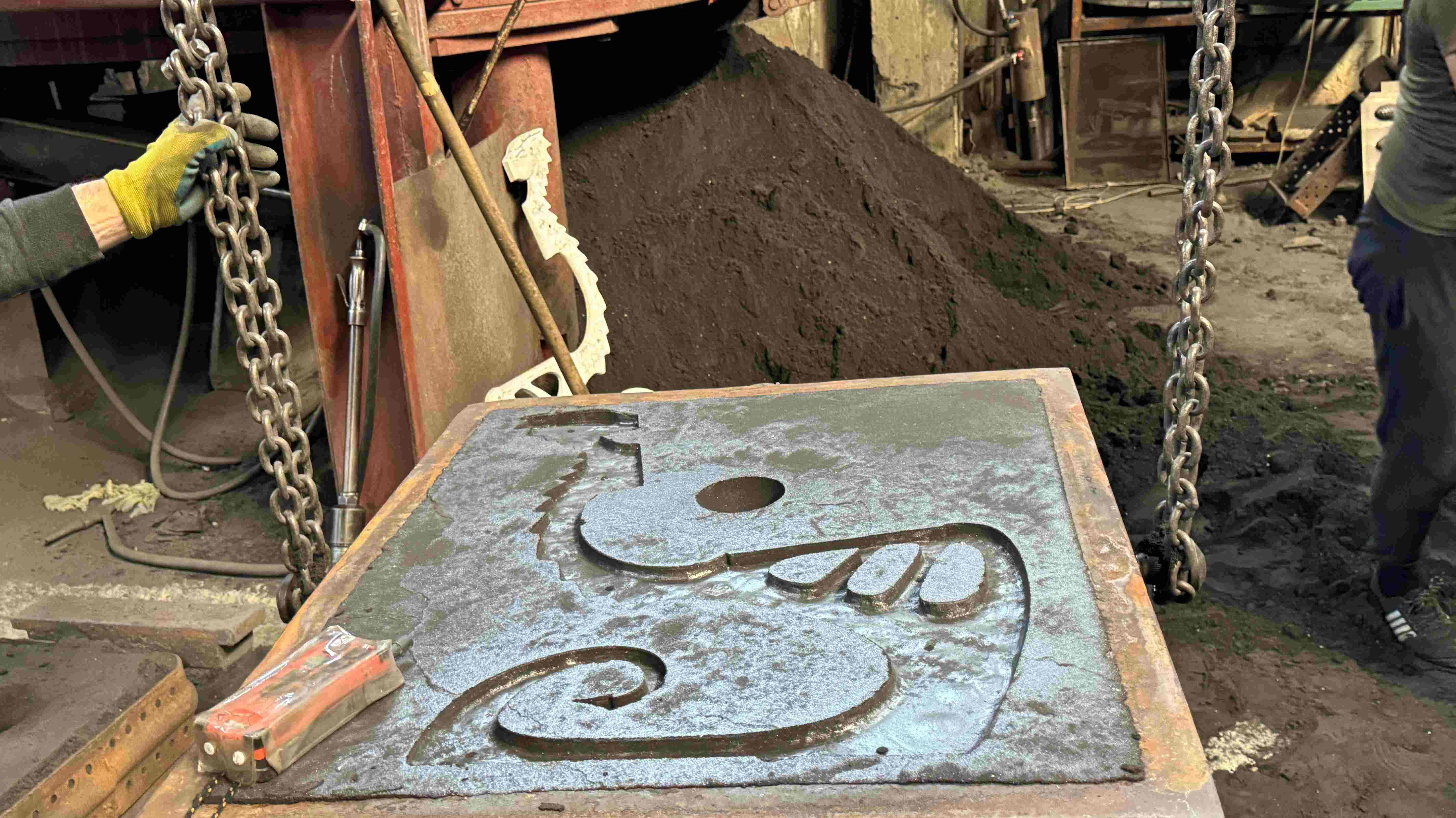
Other part of flask is being placed on the first and the same process of filling the graphite, sand and pressing. Then take out the pattern, connect two parts and the mould is done.
Specialists are pouring the melted metal through the runner.
Finally taking out the casted parts.
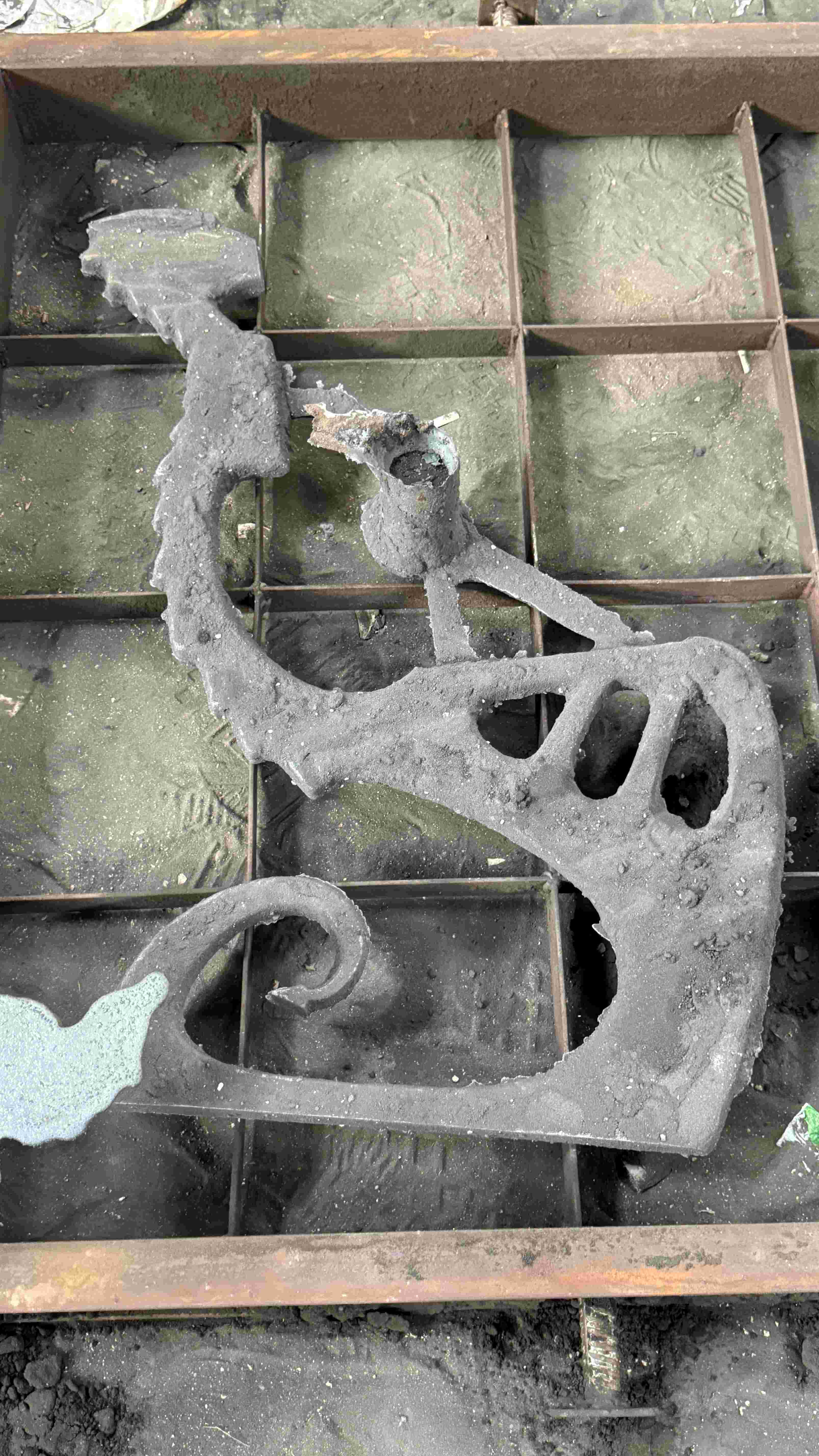
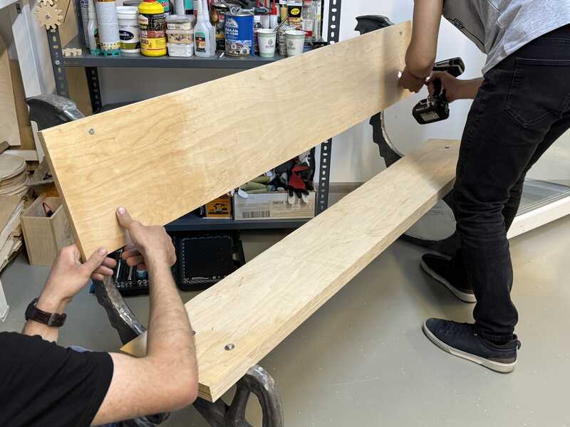
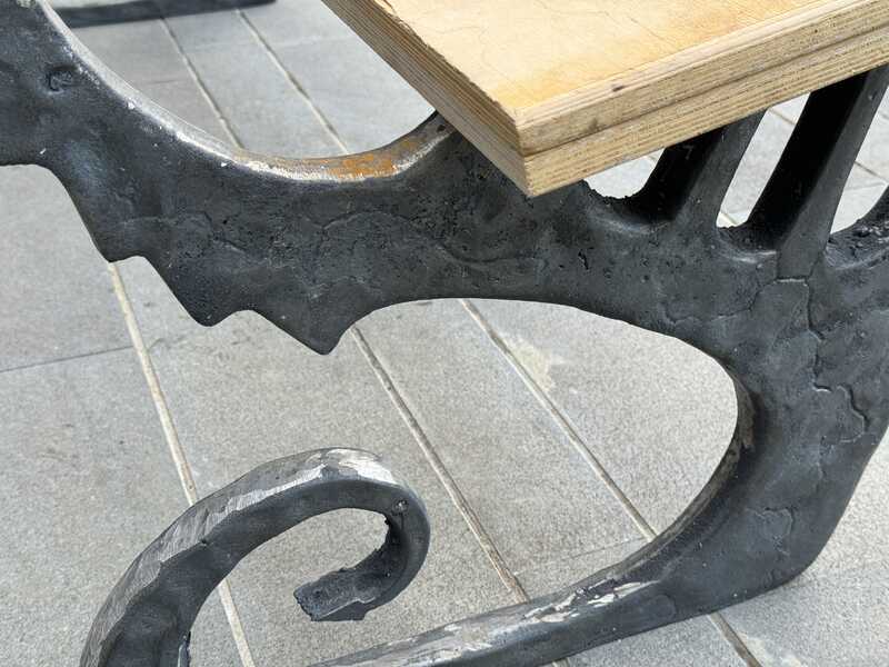
It needs to be polished. Thanks so much to Ashot’s factory specialists for polishing and cutting off supporting parts. When I got my bench’s parts ready and we started assembling feet and desks with Mkhitar and Ashot.
Mkhitar and Ashot helped to make holes and threads and we assembled the bench.
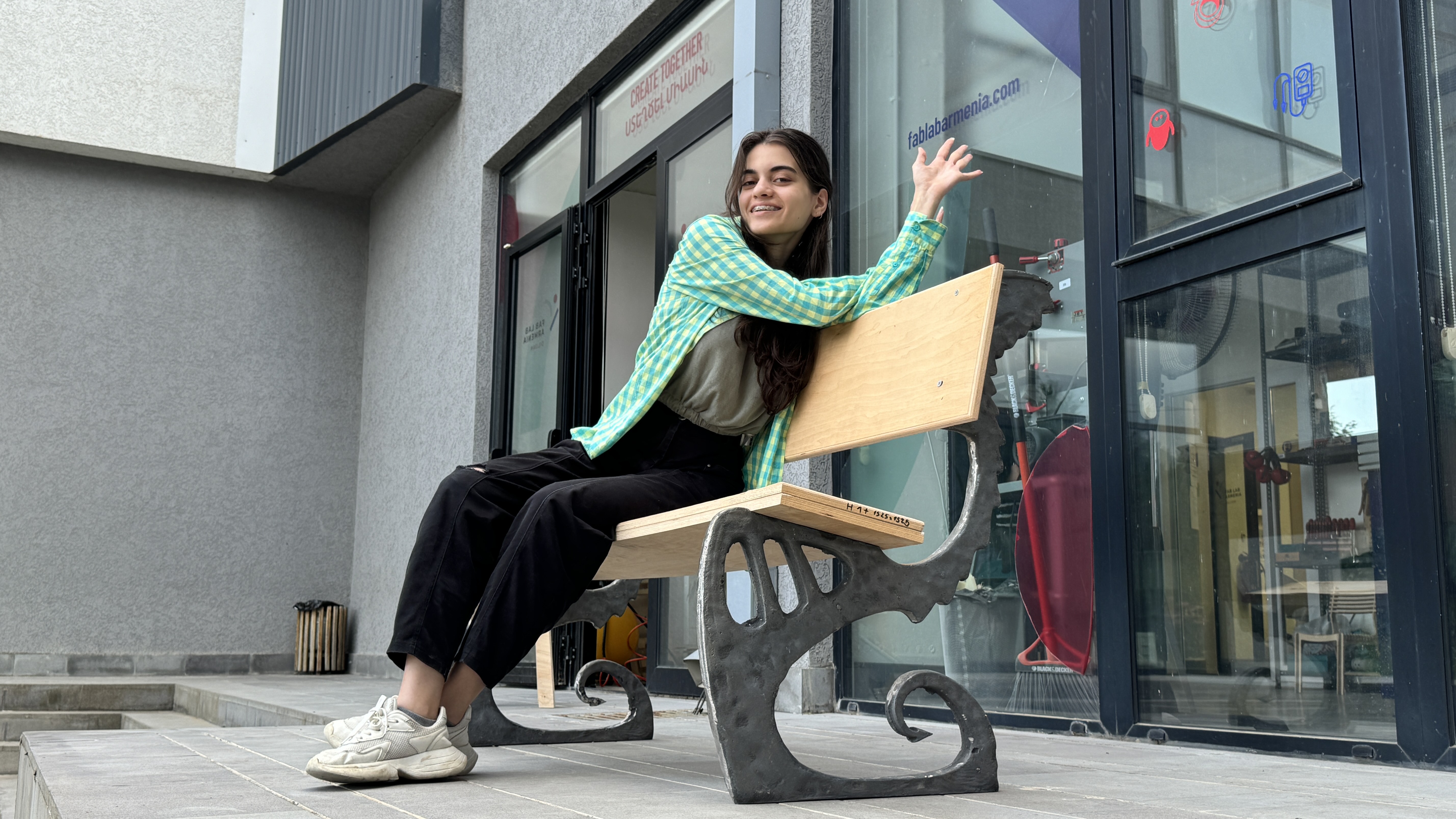
Heroshots
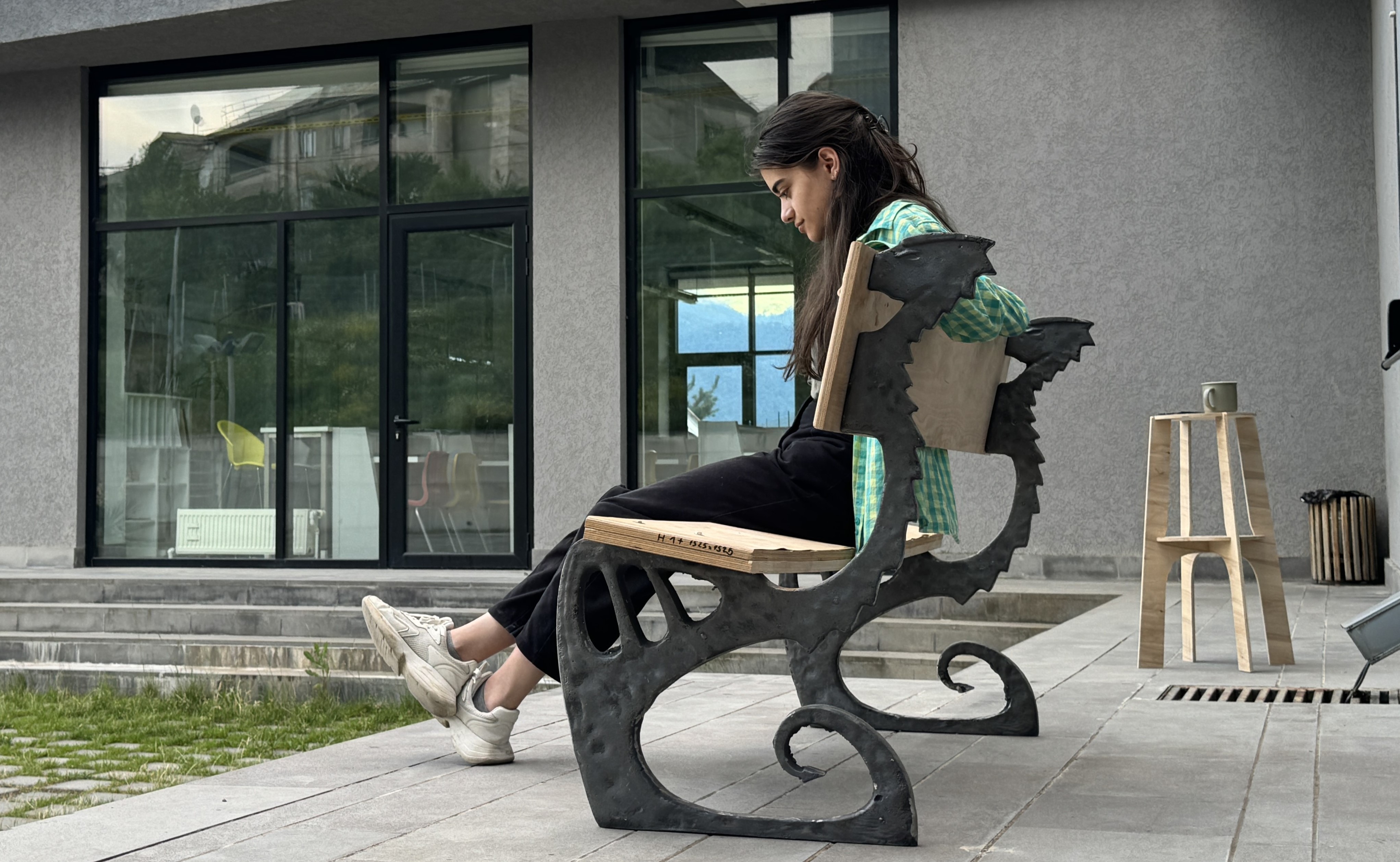
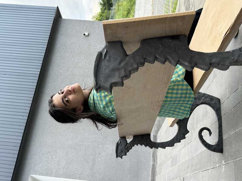
It’s placed now at the entrance of our Fab Lab in Dilijan!
Conclusion
This week was one of the most enjoyable. In addition to creating something BIG and achieving a result that I’m quite pleased with, it has been a fun week spent no sleeping near the CNC machine with some of the best people. And, of course, we’ve learned a lot and opened up new opportunities for prototyping and manufacturing our products based on our design. And again thanks to Ashot a lot for providing an opportunity to work in metal factory and instructing us during this week.