Week 7. Computer controlled machining
In short
This week we got introduced to CNC cutting machine. I used Fusion 360 to design a table and to generade a g-code for our ShopBot. In the design I used different joints and made dogbones with Fusion 360 addin. CAM processing in Fusion. Assembled with no glue. I cut out from 9 mm thickness plywood, then finished with sanding and assembled the design.
Group assignment
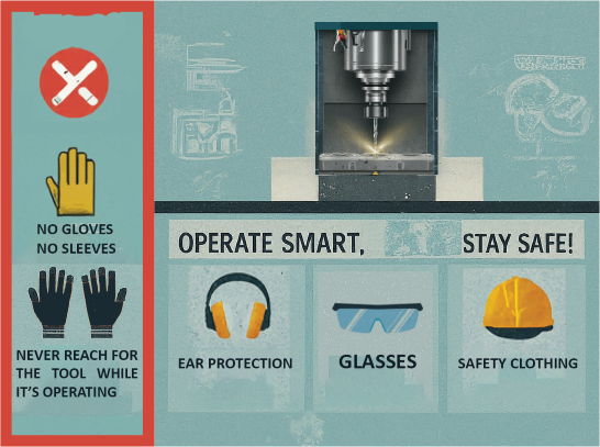
Image icons generated by AI stable diffusion, and designed by me using Photoshop.
For group assignment trainings I learned about safety rules for working with CNC machine, about it’s workflow and how to serve the machine, starting the machine and zeroing. Also how to change mills on the spindell. Used Vcarve for running the machine. Also we did a test for finding out kerf influence on the milling details widths.
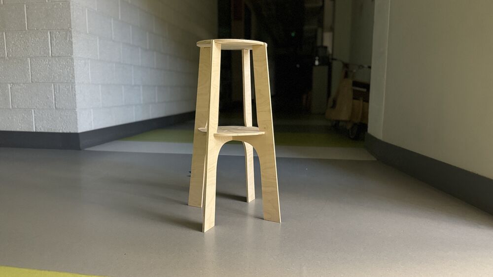
Heroshot of the design
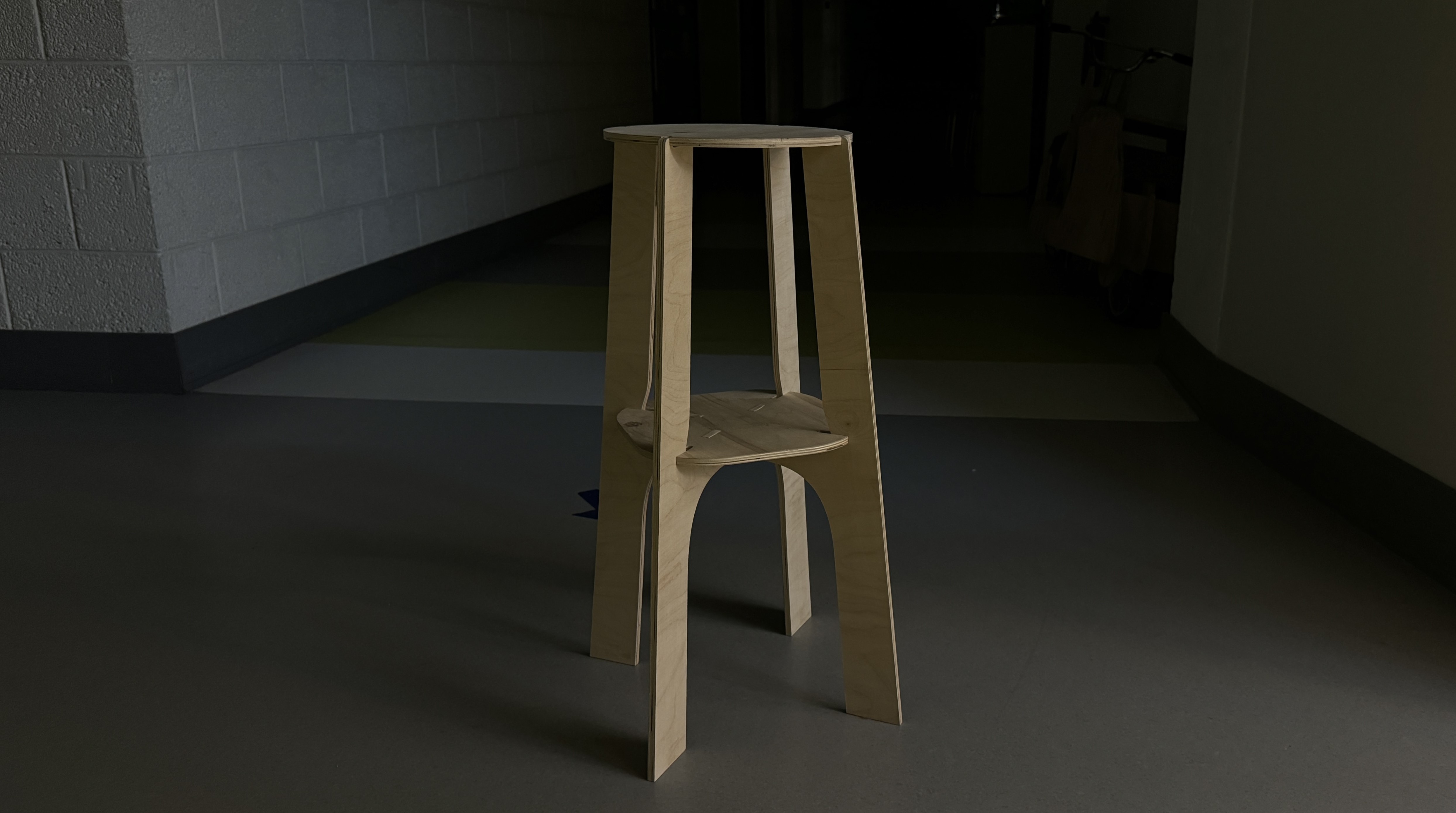
Individual assignment
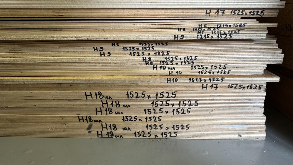
I was introduced to the materials that we had in our lab. I am choosing the thickness and thinking about what I can make with that.
Modeling
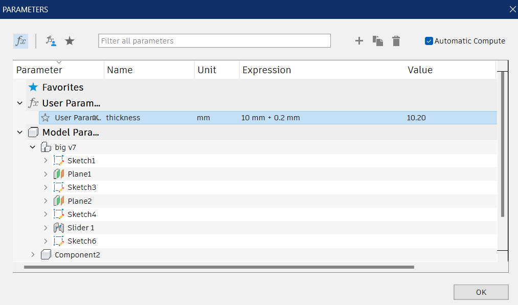
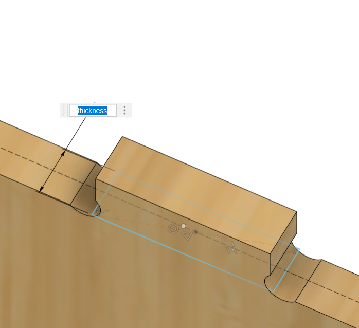
I am using Fusion 360 for drawing the model. For design I inserted the parameter of the material thickness, and I made the joints related to that parameter. This parameter is set according to previous tests in group assignment that shows the cutted part has kerf difference from the contour that’ve been cut. + 0.2mm was the result.
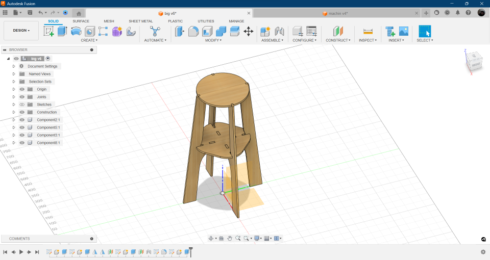
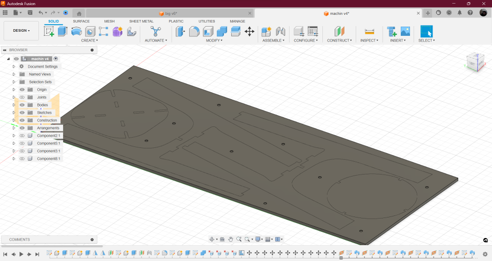
Here is the finished design.
CAM
With Ashot’s help I started generation of the g-code in Fusion 360. He suggested to dublicate the file and name it for machining. The reason is that in machining process we will move and arrange the components, and not ruin the design.
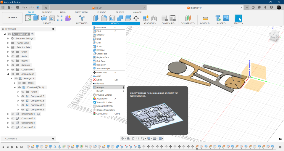
I created copy of the file. Then arranged components using the feature arrange. It requires sketch plane, so I made a sketch according to our CNC table sizes 1200*1520mm.
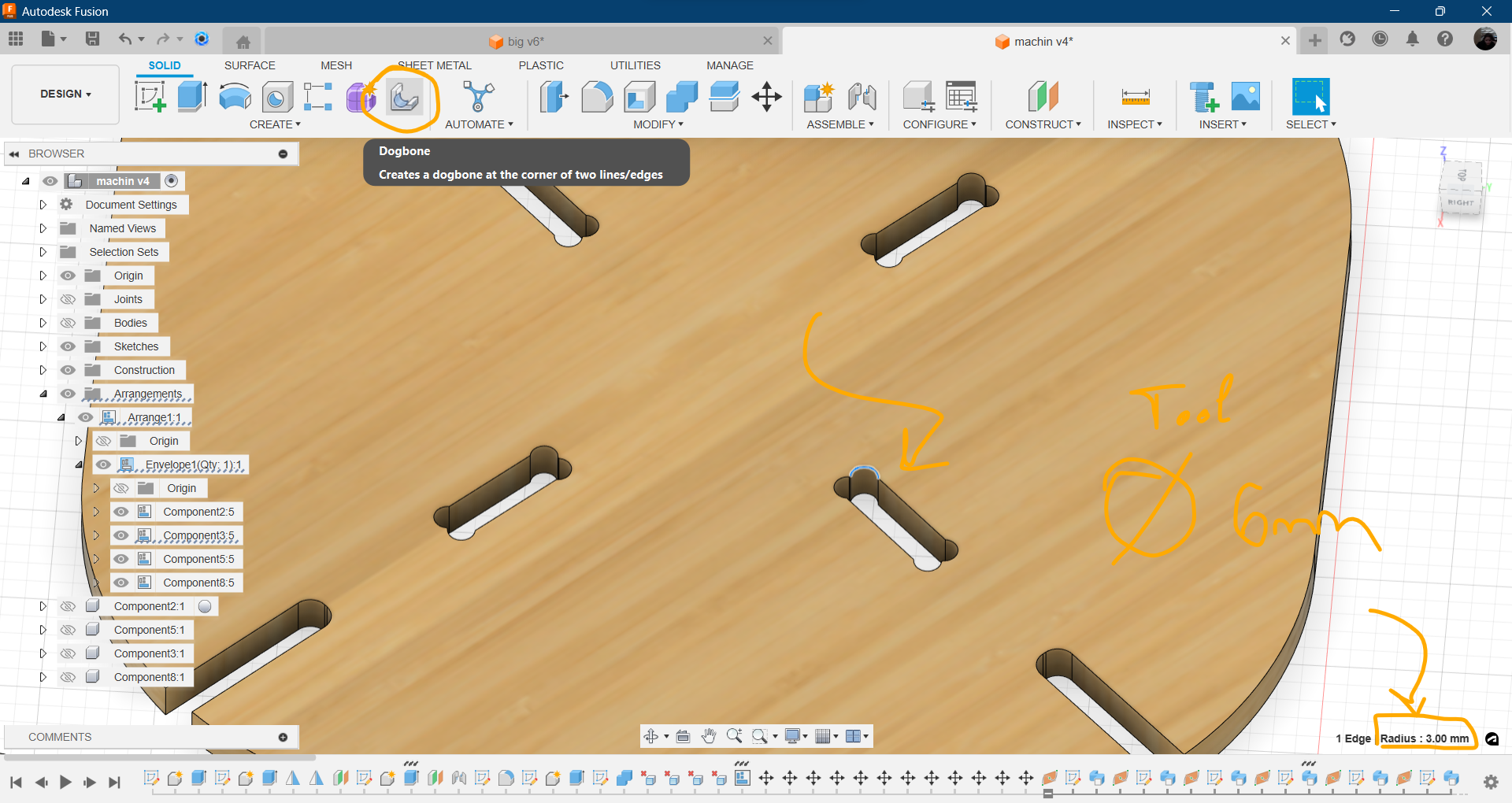
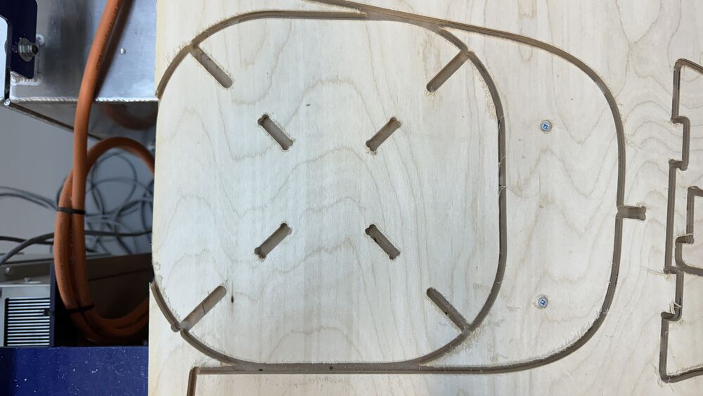
For dogbones there is an add-in for Fusion 360. Here is a link. I used it to generate dogbones on the joints. As we are using mill with diameter 6 mm, I type that value into the addin options and it makes dogbones.
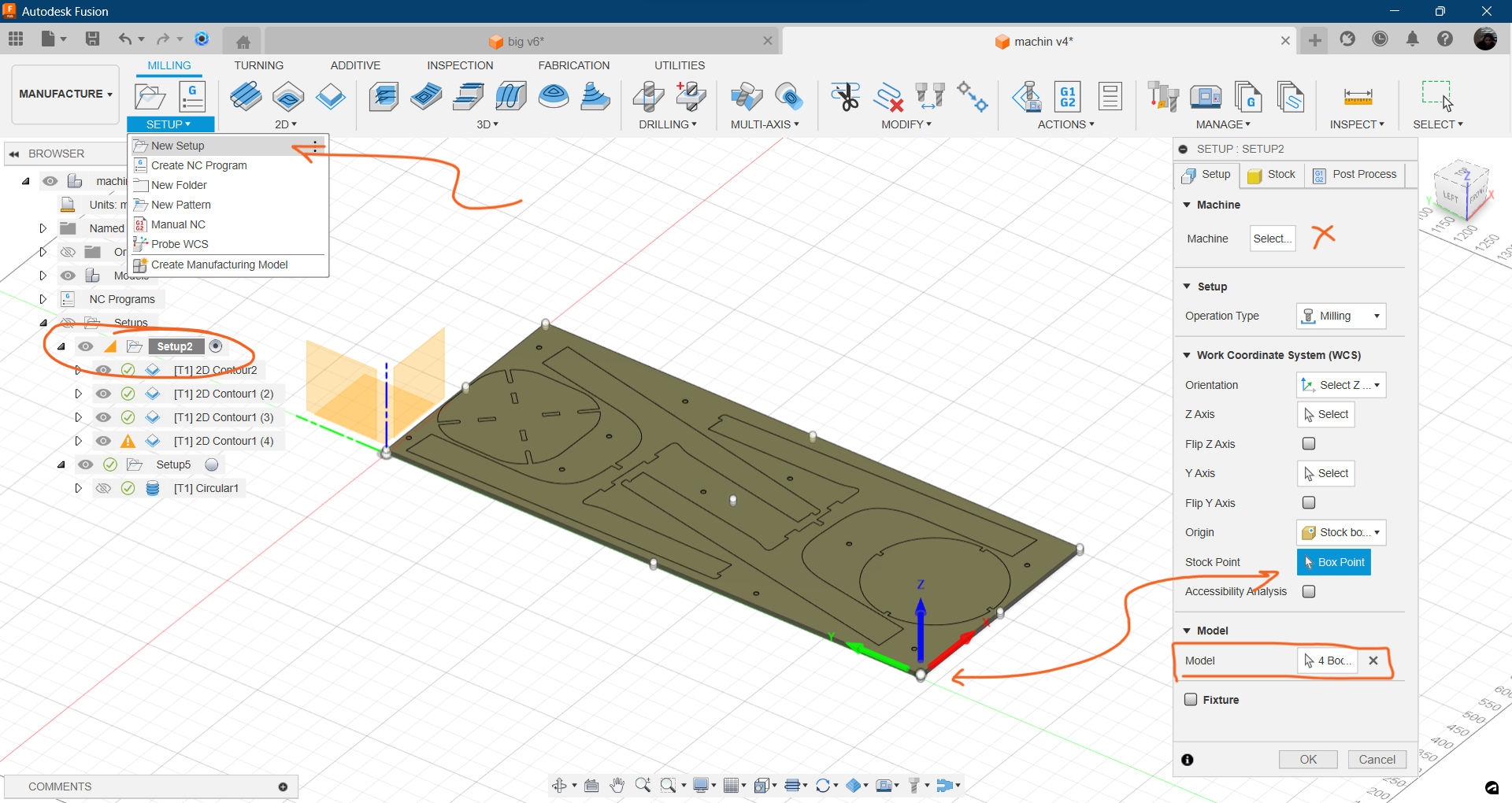
After we can switch to manufacture tab.
-
setup
I left machine unselected because in Fusion library the Shopbot wasn’t in the list. Choosing machine is just making simulation with real machine animation. We can insert machine’s parameters later manually.
-
choose models from our components
- choose origin same as the machine’s
choose the piont where the cnc machine’s zero point is
- select box fixed size cube
Finished with setup. Now select in the 2D dropdown menu contour
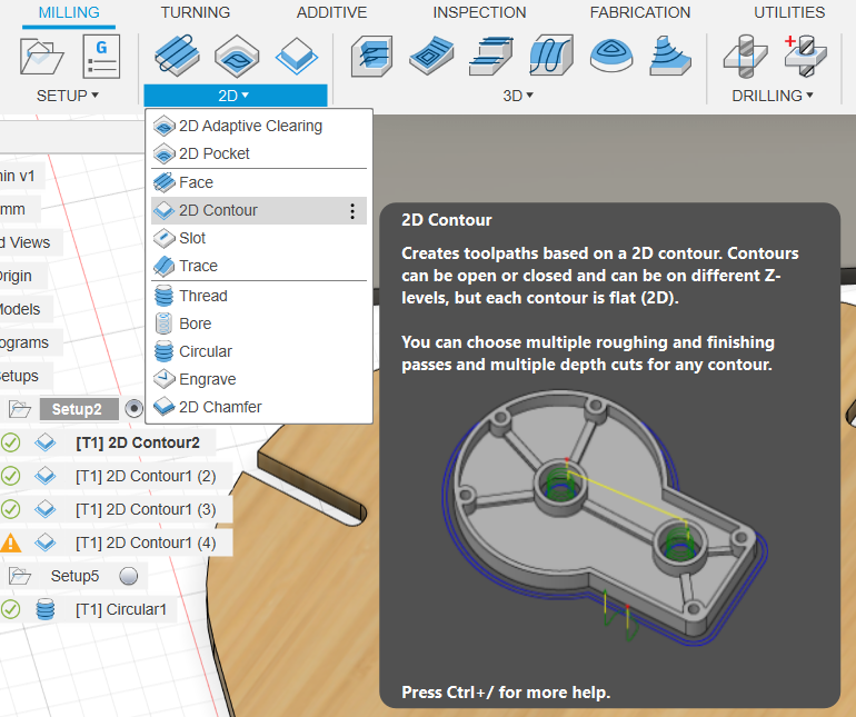
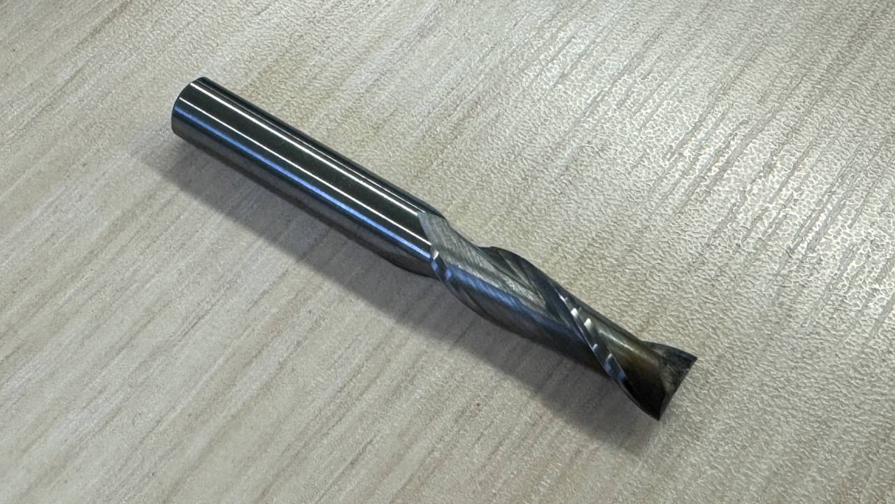
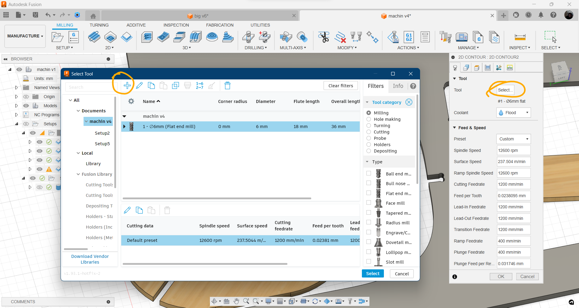
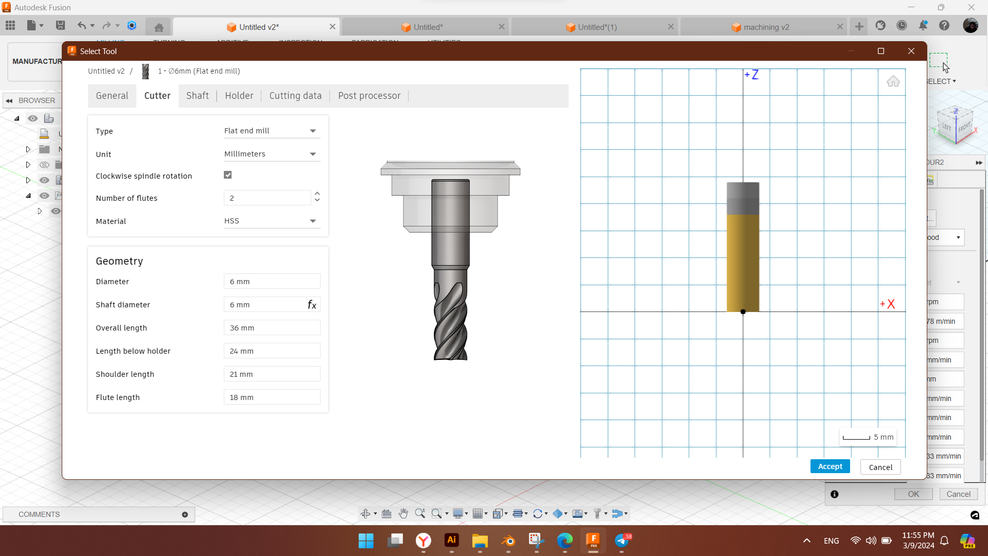
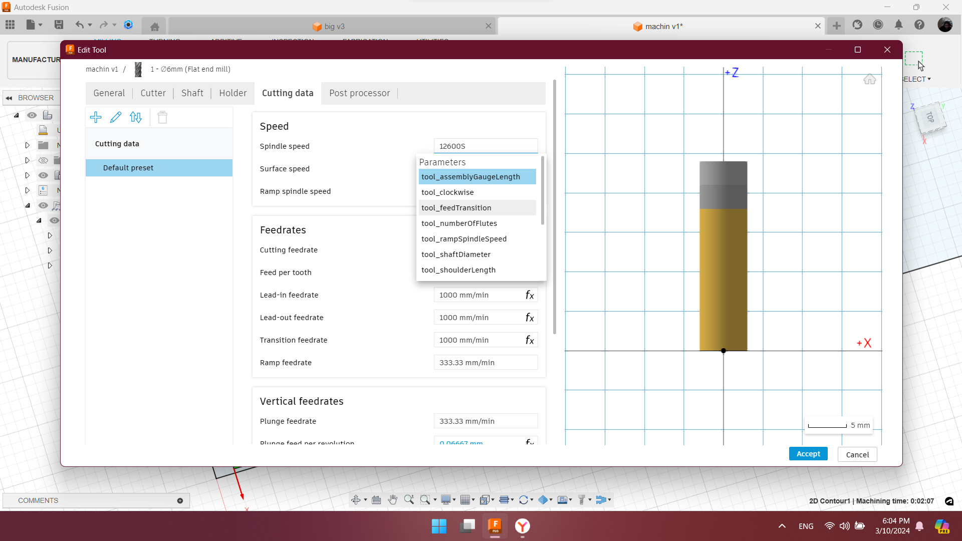
Select the tool. We use upcut flat end mill, 6mm diameter. Copy tool parameters from Fusion 360 library, and paste in local library to have the tool.
After selecting mill it’s needed to
- select the contours to be cutted.
select bottom contour
- adjust stepover
it’s good to set half size of the mill diameter. our’s is 6mm so we could set 3mm, but for safety we set 2mm not to brake the mill.
Finish first contours. We can dublicate now this setting and clear the selected contours and choose the next contours to be cutted.
For the next contours I needed to set tabs.
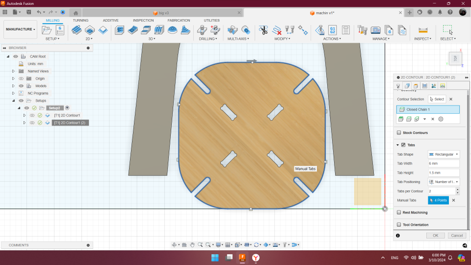
and that for all contours. Contours are going to be cutted in the order same as shown in the Fusion 360 browser in setup.
To safely screw down the desk on the cnc plate I needed to define the areas where the screws would not be on my table parts.
So I went back to design and I sketched a 10 mm diameter circles on the safe places. extruded the board with letting that holes under 1 mm. and let the machine make 1mm deep holes for noting the places where to screw down the desk.
Switch back to the Manufacture New setup for this holes. I am going to have 2 g-codes. One for holes, second for cutting.
From 2D dropdown menu select circular.
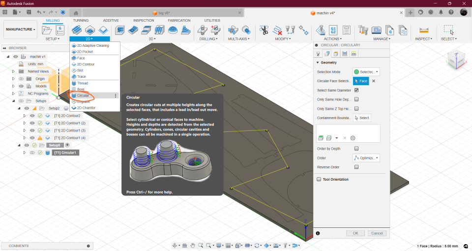
Set the
- multiple depths: 1mm
- retraction height: 50 mm
we are going to fix the desk with clamps untill the holes for screws are done. And the reason of high retracting is the spindle not to hit the clamps while moving.
Post processing
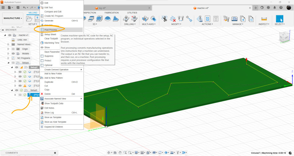
right click on the setup and choose post process.
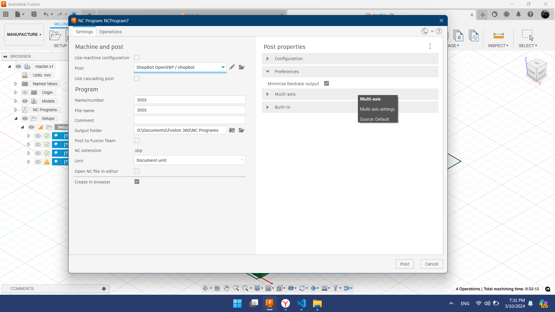
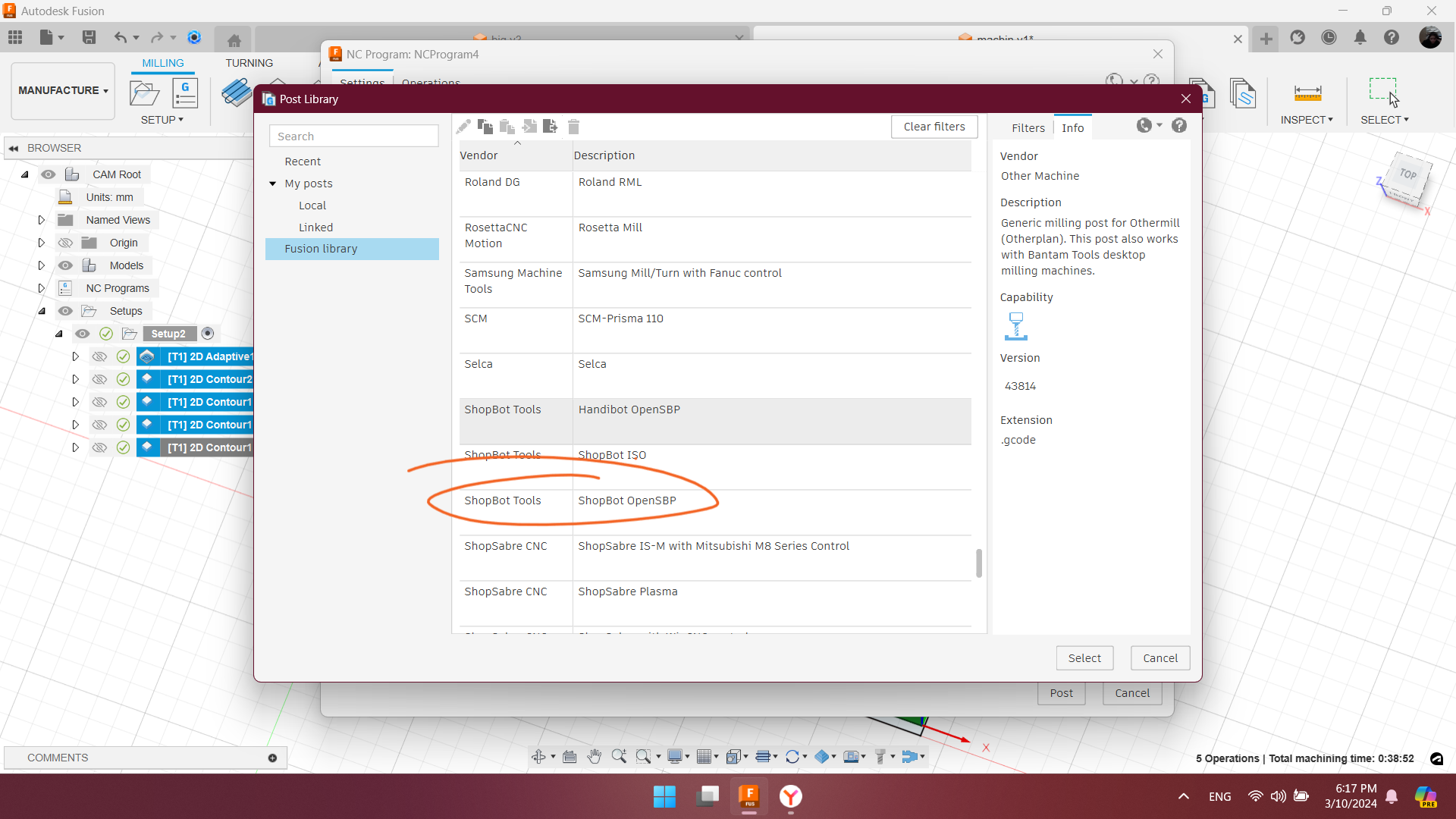
Find the ShopBot post processor ShopBot OpenSBP and select.
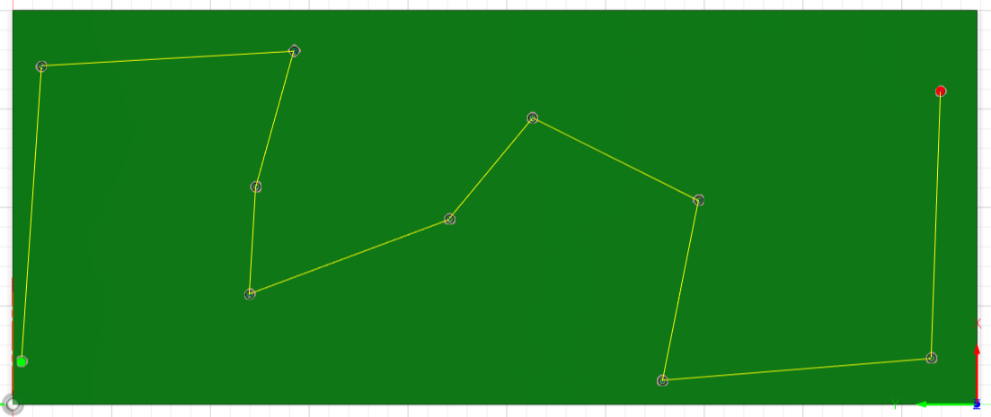
Then by clicking post-process keeping selected one toolpath it generates .sbp file. In case of selecting multiple toolpaths it generates one g-code for all selected toolpaths in their order.
So I’ve generated one separate g-code for drilling the holes and one g-code for remaining toolpats which were being cut with same mill.
Done generating a g-code in fusion 360.
Assembling
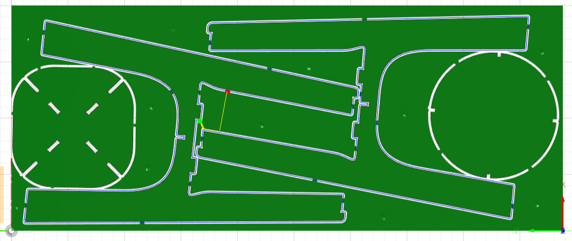
After milling holes and screwing down on the bed, next step was milling the small parts like inner dogbones.
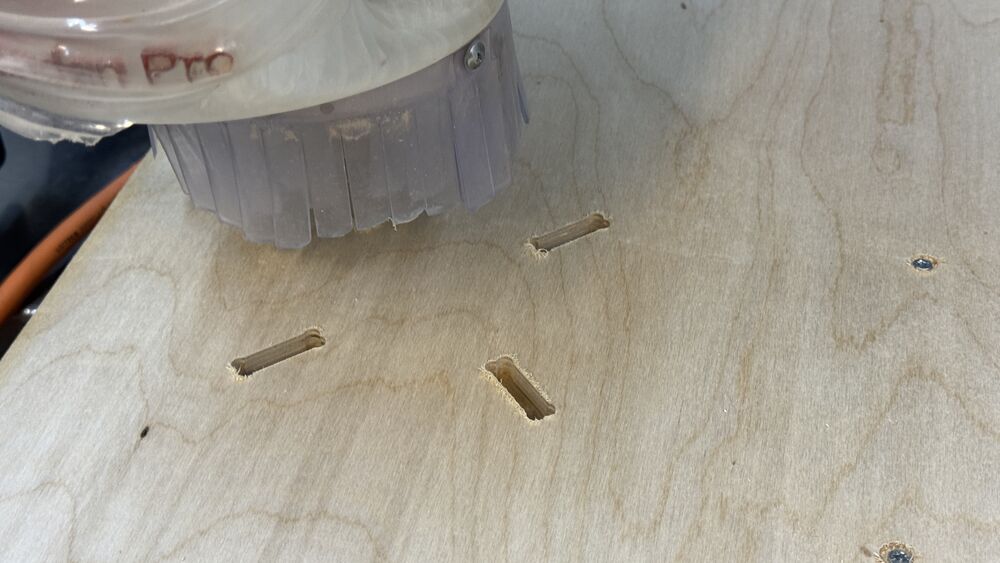
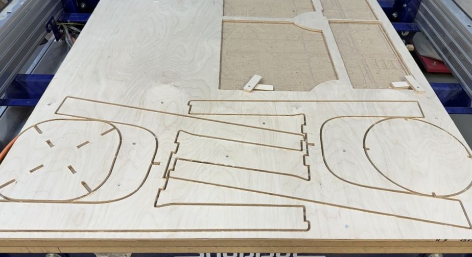
I arranged and placed the models the way to use minimum of space on a material.
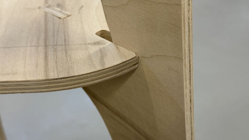
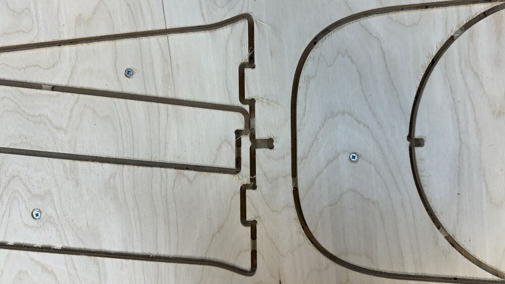
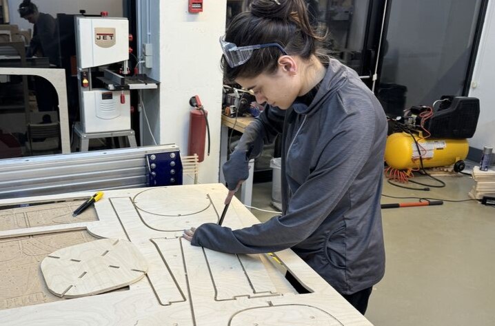
So all the parts were cut, parts were taken off and it was remaining to cut tabs manually and finish the surfaces with sanding.
Sewing off tabs.
After sandpaper process I assembled parts. Assembling was done wihout glue, parts were fitting good, used hammer to help me slide the bottom table surface along the feet. and here is te final result.