Week 4. Electronics production
Short
This week we start introducing to electronics. We make PCB with milling machine and then solder components on boart of the Quentorres PCB example for getting aquinted to the milling and soldering techniques. This was my first introduction to electronics and my first soldering.
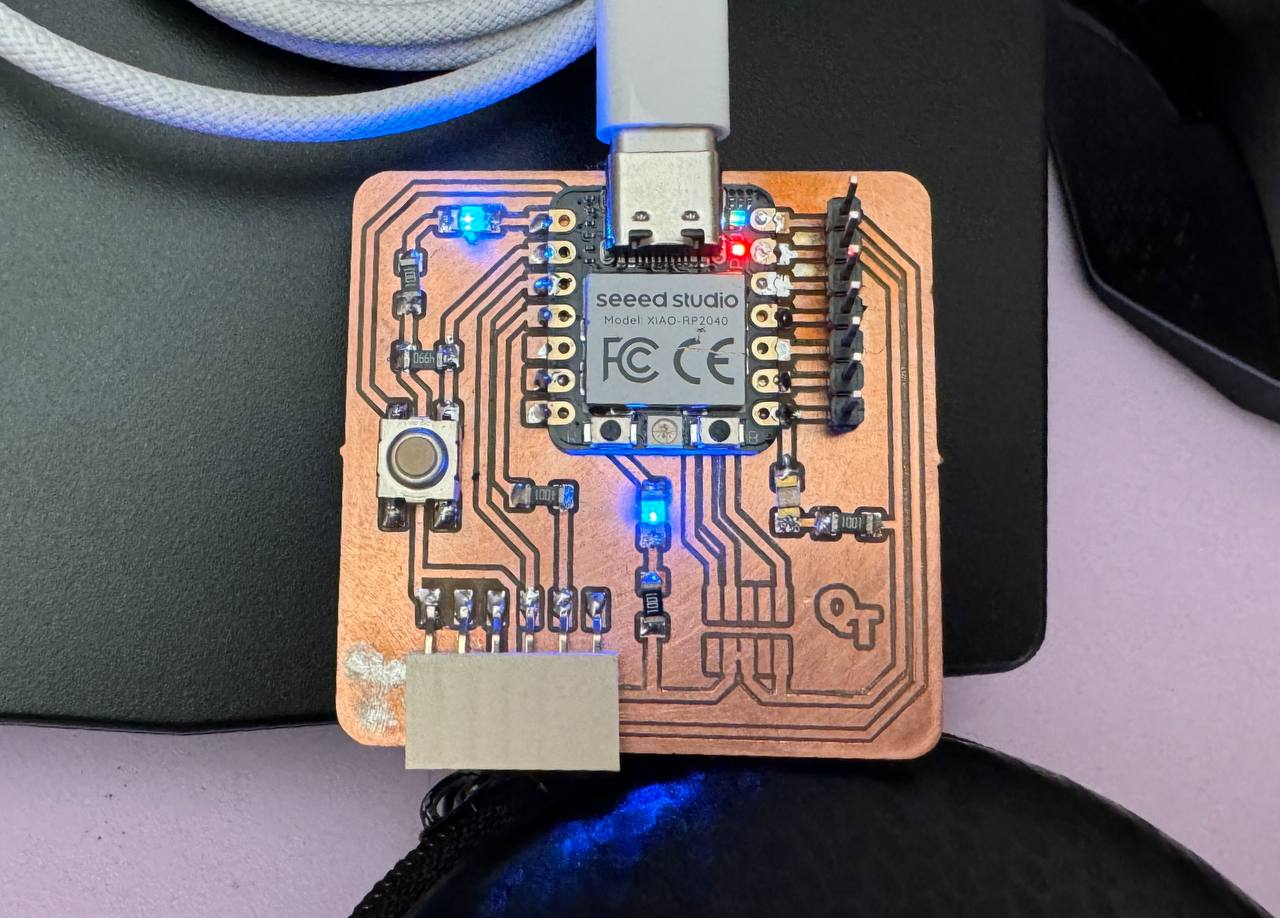
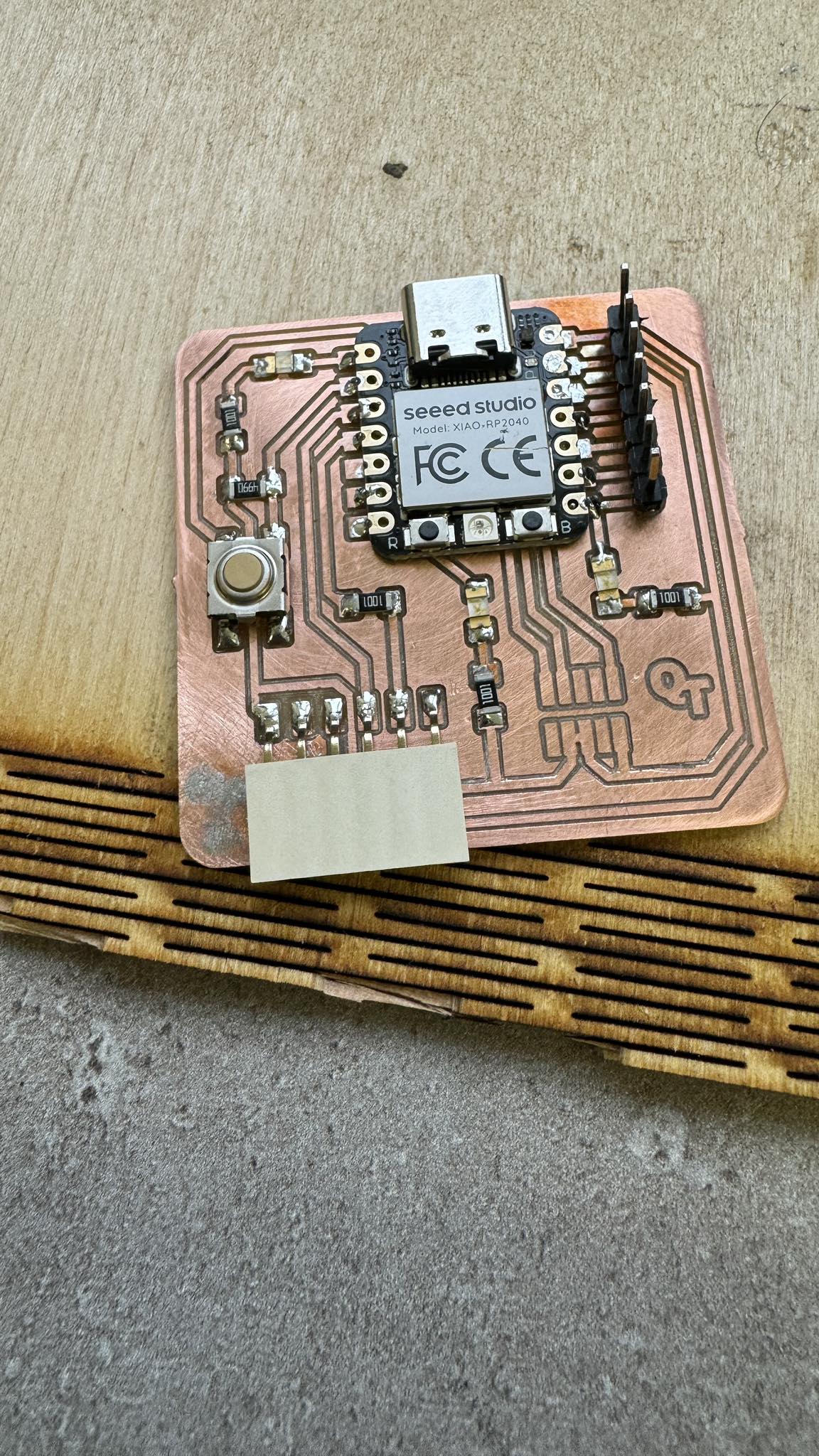
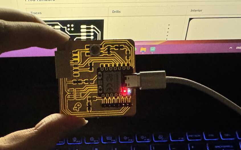
Heroshot of my QT circuit with blinking programm embedded.
Quentorres
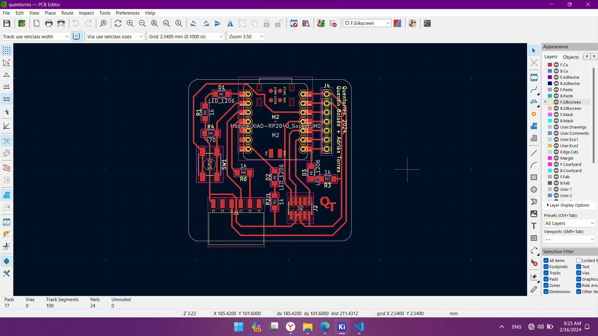
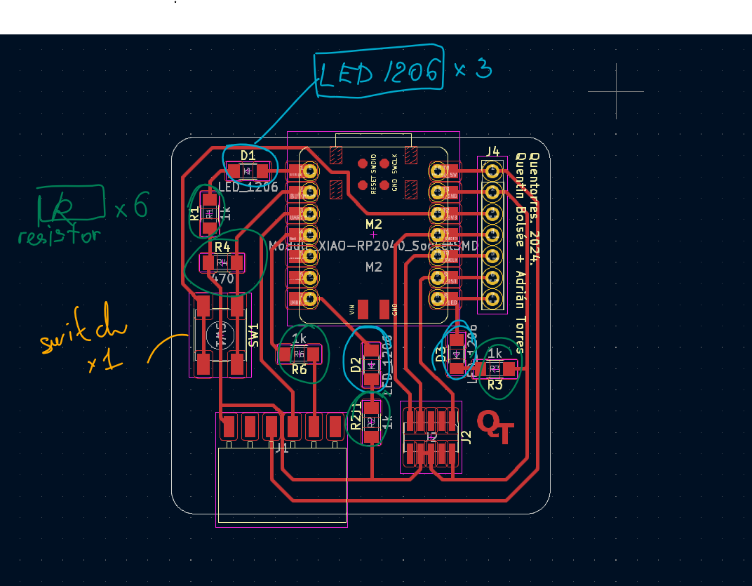
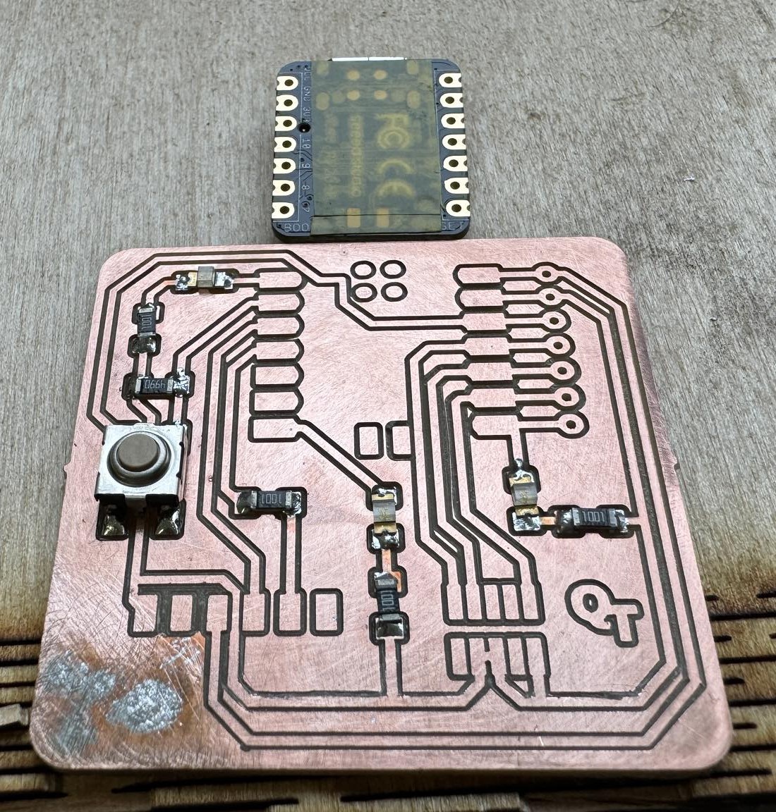
This is Quentorres PCB created by Quentin Bolsée and redesigned by Adrián Torres. The files I downloaded and opened with KiCAD. Here I can see a switch button, LEDs, resistors, Seeed studio chip, microcontroller and other components on this circuit.
Milling
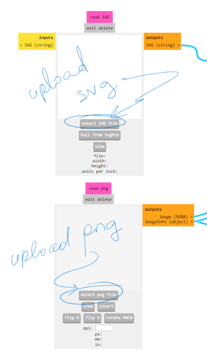
As we need to generate g-code with modsproject, we need either PNG or SVG from here
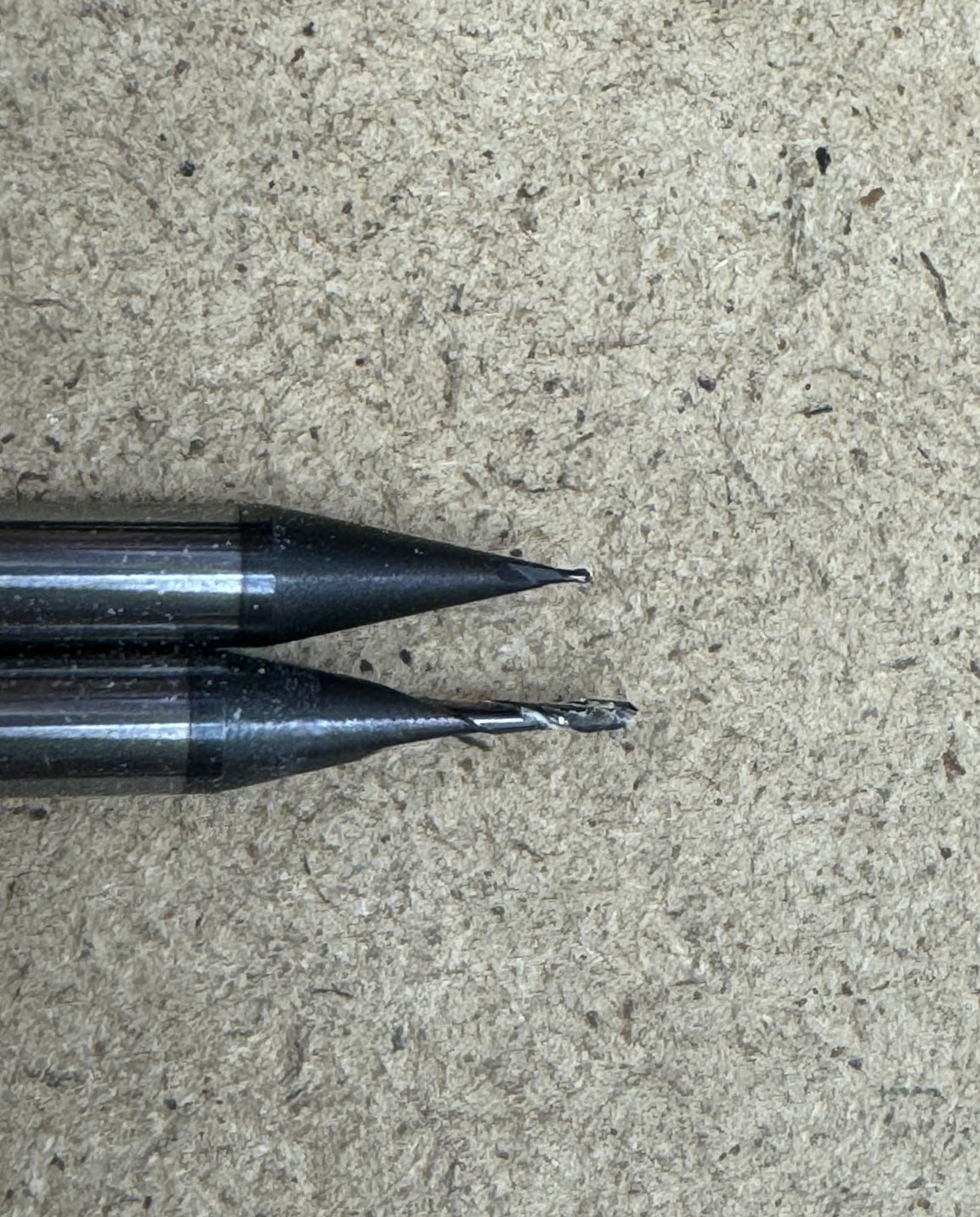
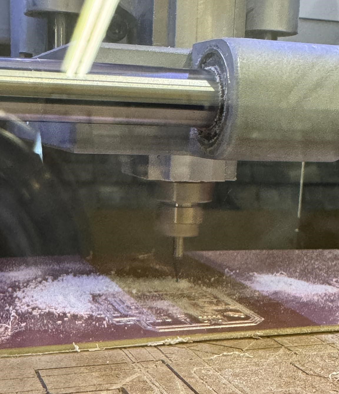
So milling does Roland SRM 20 machine. We use copper boards. For isolating traces or drilling holes and cutting out the PCB we use different thickness mills. 1/64” and 1/32”
As our board was already drawn and we had PNG files, so we needed only to generate G-code from it. For that we used modsproject.
R click > programs > new program > G-code > Mill PCB
Upload PNG or SVG files. In my case Select png file.
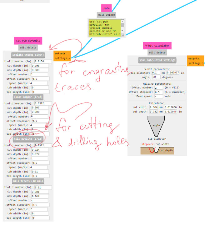
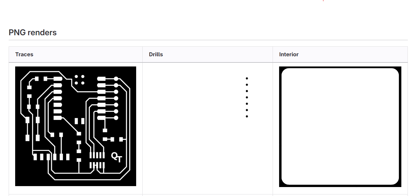
- Traces
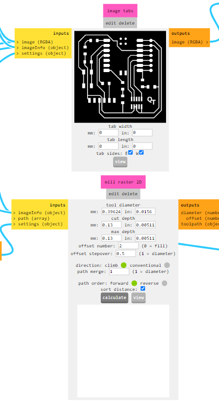
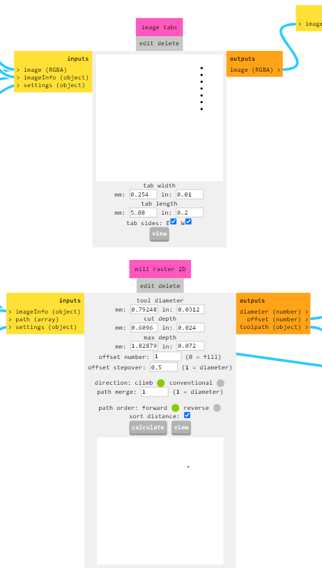
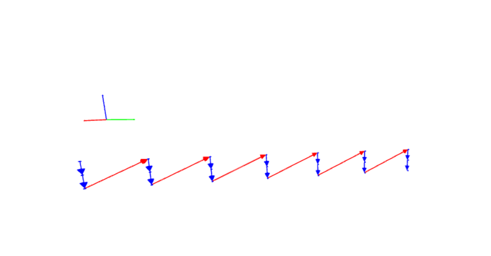
Upload the PNG file of traces. Choose isolate traces, which does offset for paths, to left copper on paths and clears the side areas not to interact paths with each other. We can choose offset width and stepover 0.5 is 50 % that means it goes and returns on the area cleaning it by the distance 50% of mill’s thickness.
Then calculate the result and the G-code generated .nc fle is saved to our computer.
- Drill
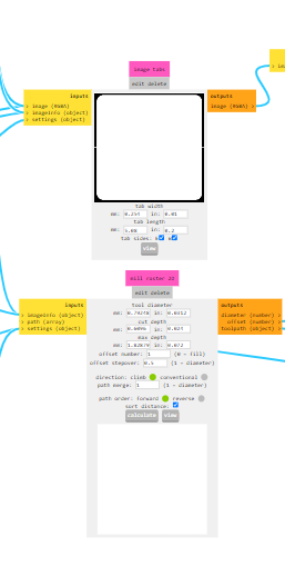
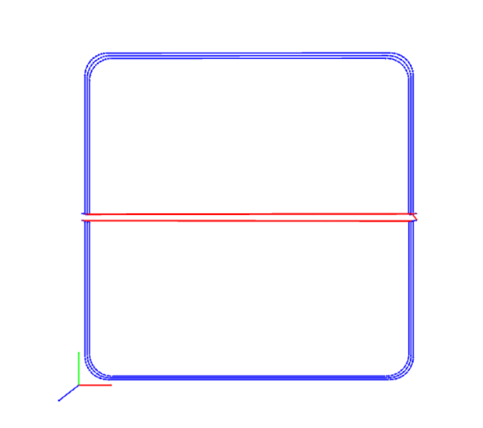
- Outline
And the last one is interior file. It is to cut out PCB from whole board. For Outline and mill outline are same parameters. Choose drill also and calculate.
Files are in the Source files
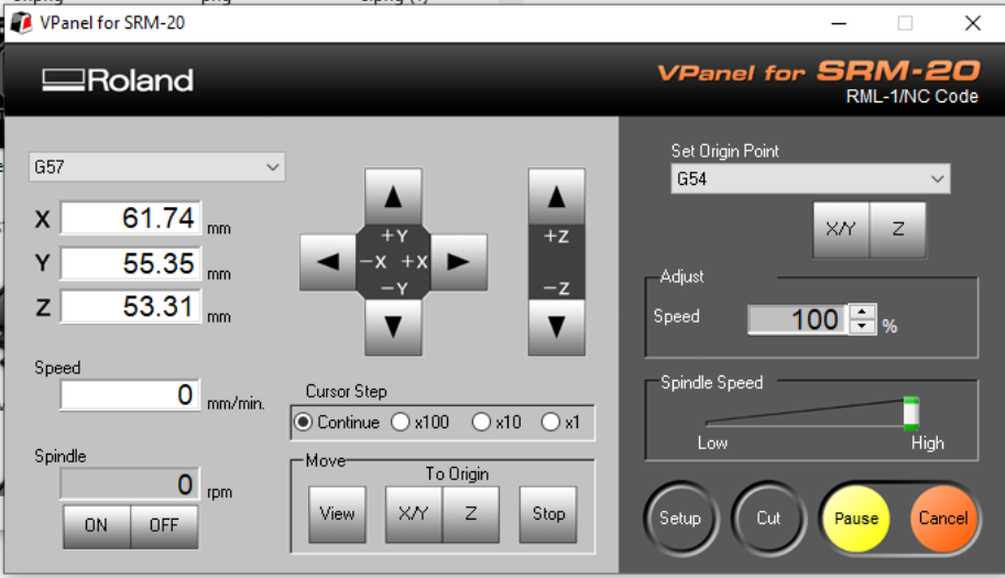
The programm that drives the machine is Vpanel for SRM. We import G-codes right into the program.
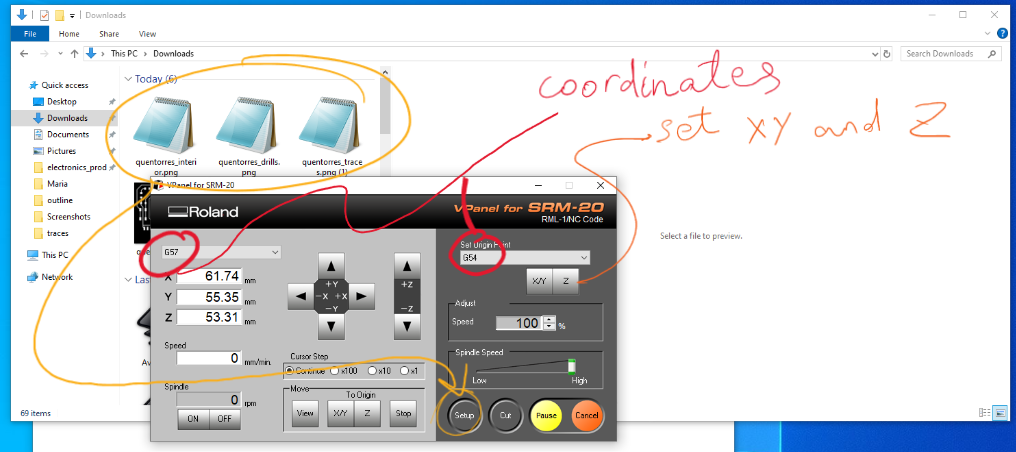
Choose Origin Point and make sure G-57(or another one) is selected same on both dropdown lists.
Next step we set up the copper board.
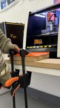 So first thing we get copper board and stick on cutting board of the machine. For that we use two side tape or clips. I used tape and sticked two thick tapes under all board. Then sticked it on cutting board and pressed with clamps for better adhesion. This I placed in machine’s work area and adjusted the screws.
Then I screwed carefully the milling drill out and changed to required size for removing copper mill.
So first thing we get copper board and stick on cutting board of the machine. For that we use two side tape or clips. I used tape and sticked two thick tapes under all board. Then sticked it on cutting board and pressed with clamps for better adhesion. This I placed in machine’s work area and adjusted the screws.
Then I screwed carefully the milling drill out and changed to required size for removing copper mill.
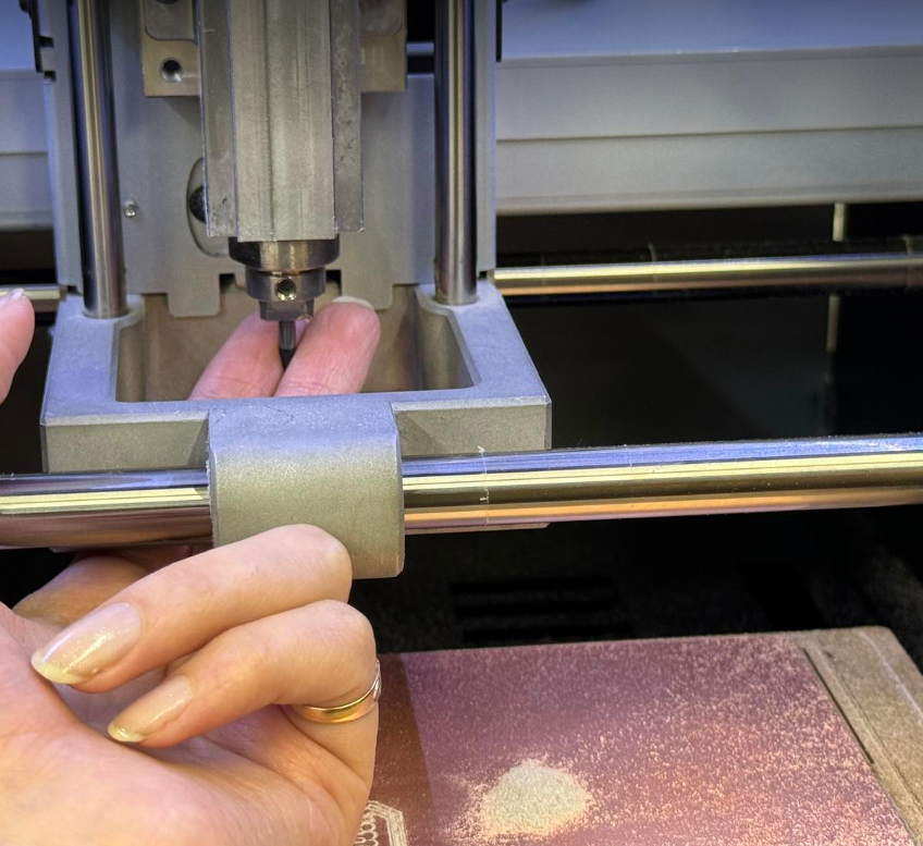
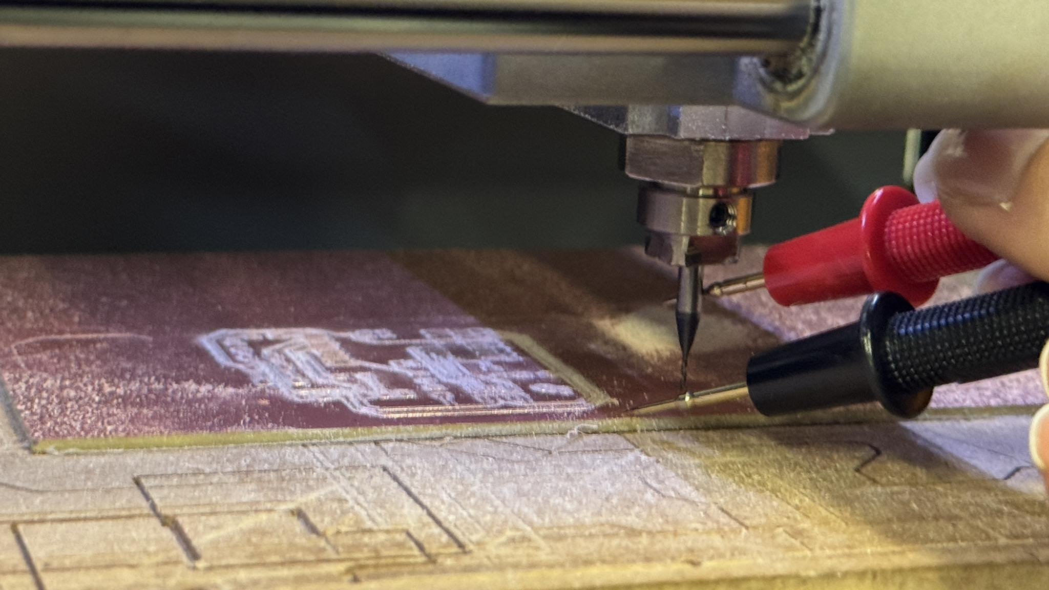
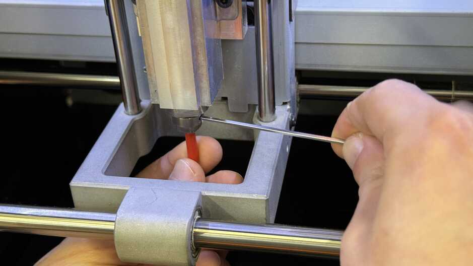
After it’s needed to adjust zero points of XY and Z axes. For that I lower down the head enough to keep about 1 mm above the mill. Then it’s needed to adjust manually. I hold with fingers the mill to protect it from falling and relax the joint so the mill will get down and touch the ground. And then tighten back the set screw. Choose Z to set up this position as 0 for Z. Then pull up and place approximately the XY start point. It must be left bottom side. Set XY as it’s zero coordinate. Or the another method af adjusting Z point, is to keep one cabel of the multimeter on the endmill and another on copper (continuity mode) and lower Z axes with little steps 0.1mm while it starts beeping.
I tested also the second method of adjusting Z axes - with multimeter
When zero points are set, select first isolating traces file.
Press Cut > delete all files > add file.
choose first the isolating traces file’s G-code. and output.
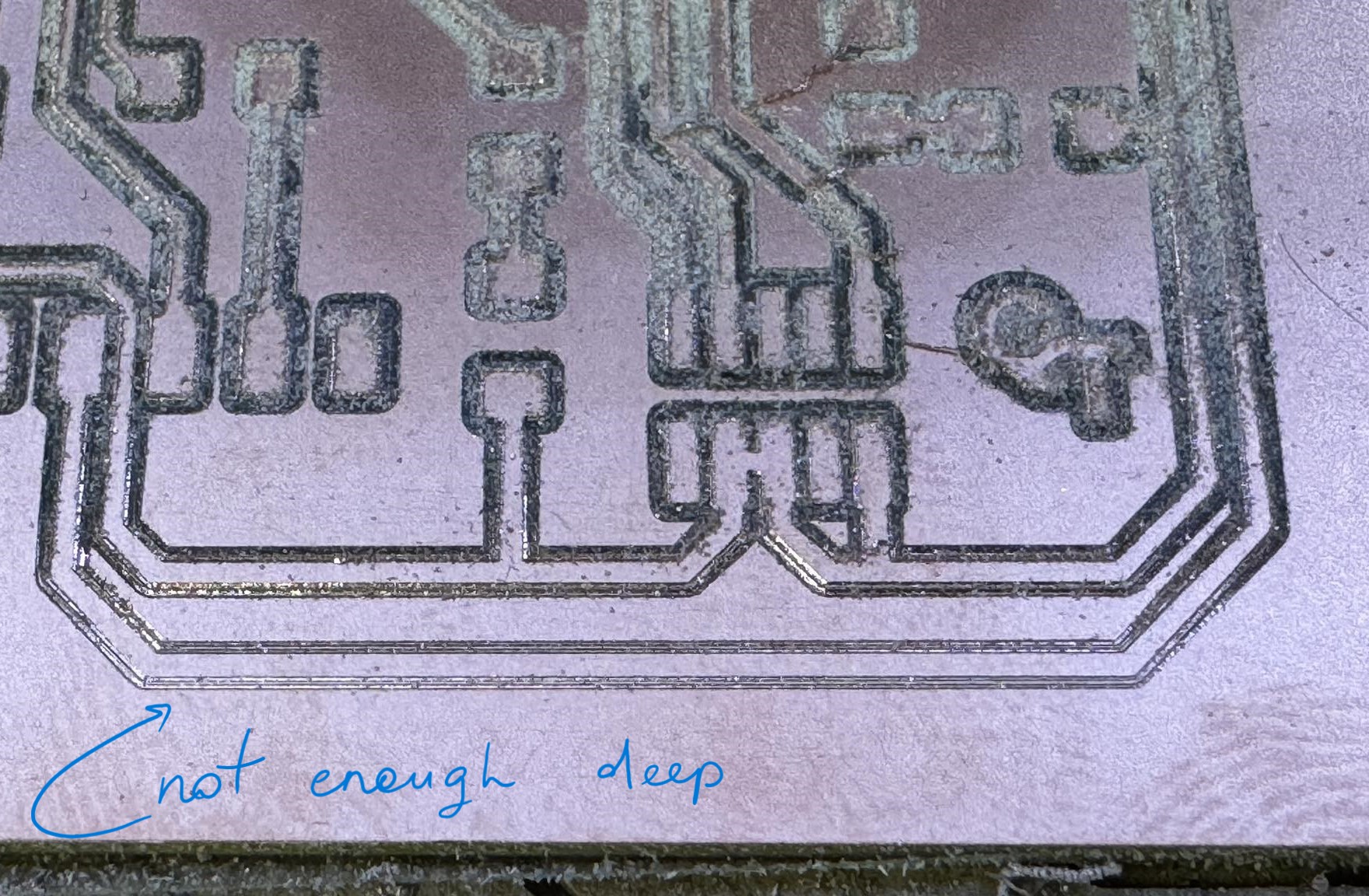
If something goes wrong press cancel or pause. In my case the copper board was a little bit bended, because of tape and it milled some part not enough deep as the board was a bit lower than the depth set up.
Problems
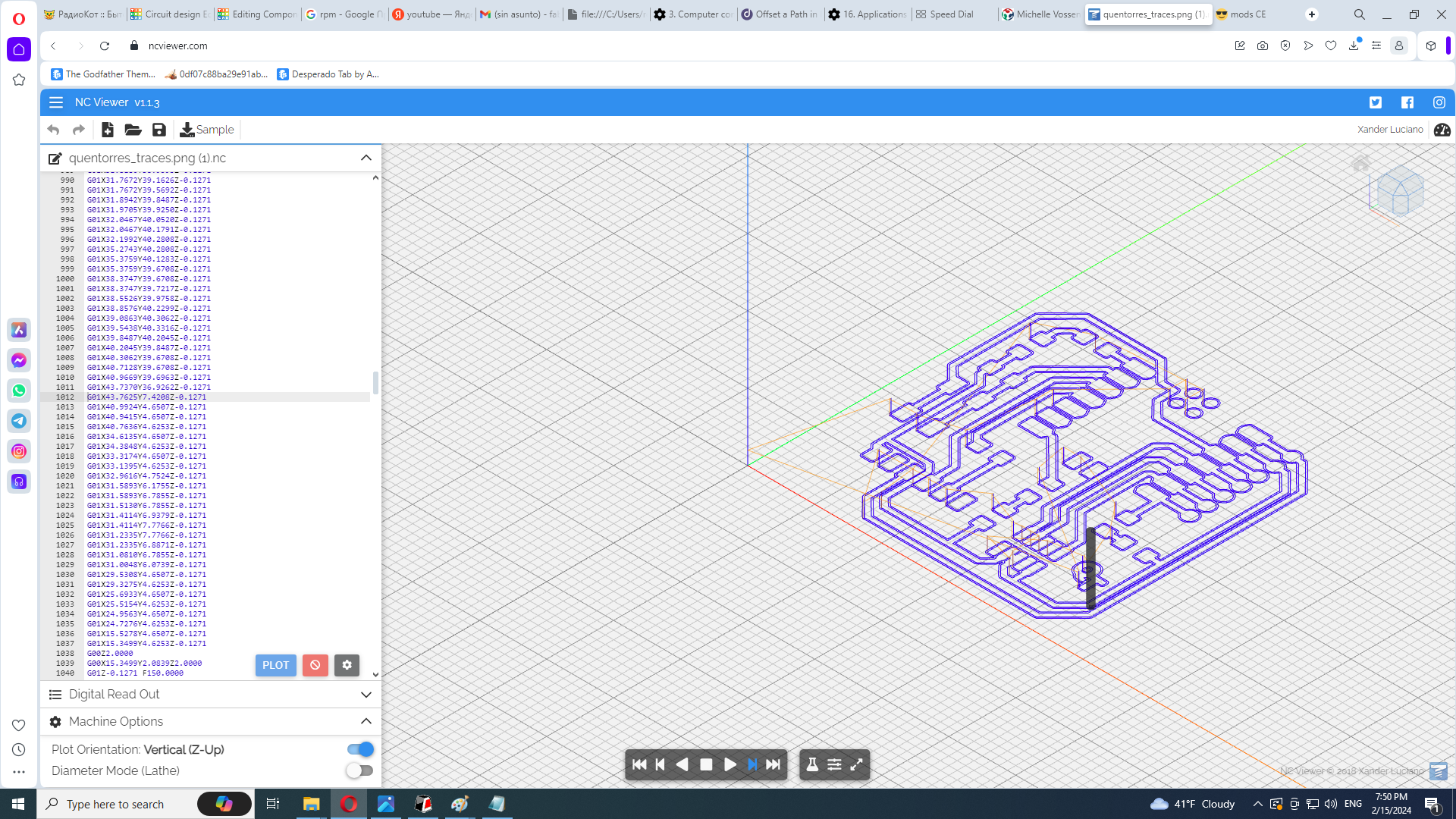
I thought we can set the mill to go through that part again and make it cut deeper. But the PNG file cropped to the required part wouldn’t work because it will start cut from edge of the image. So our instructor Maxime, who was instructing us the process of making PCBs, offered to modify the G-code and let the parts where it should mill again. He used ncviewer to simulate g-code and found the required parts. He deleted all unnecessary parts and let the machine to mill again through the part which wasn’t milled well.
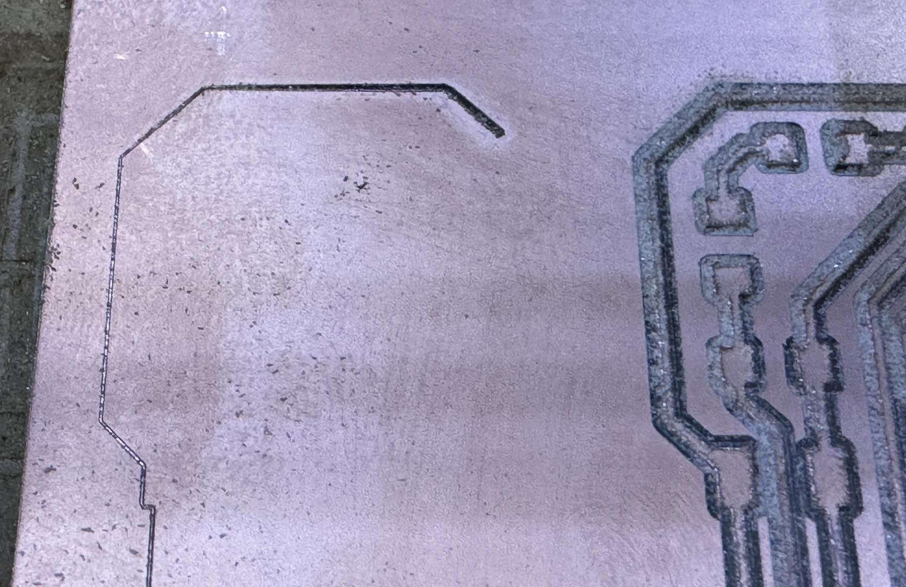
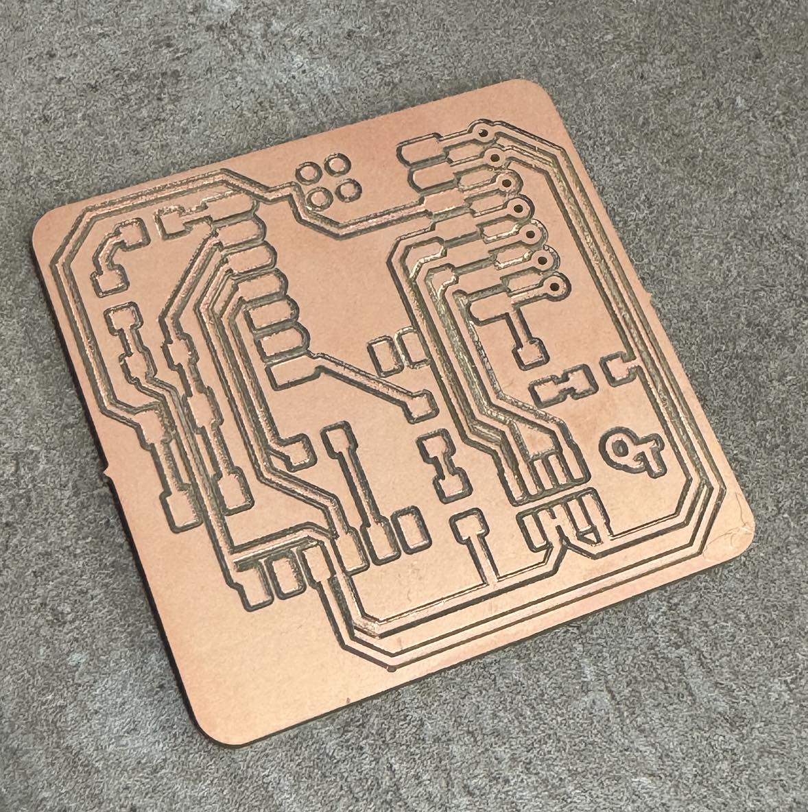
And we again set up the zero point and make the new code output. It cut well this time.
It looked good and we decided to continue.
Soldering
After we set the drill file. And then we started to mill to interior file. On the last try the copper board unsticked from the board and started shaking while cutting. We paused the machine, set view mode and sticked down to finish this work and see how it worked. Then resumed the cut and it finished nice after sticking the board down. We took it out and check if there are any short cuts with multimeter. Test showed good results, all was right.
After this I headed to search and collect all the required components on the circuit that I can racognise on the drawing with matching sizes and parameters. I found resistors and diods, then with Shushan we found right switch buttons and connector headers from our component shelf in Fablab. And after that instructors gave us the remaining parts that we hadn’t recognize.
So we started training on old circuits then when we felt a little bit confident we started soldering our PCBs.
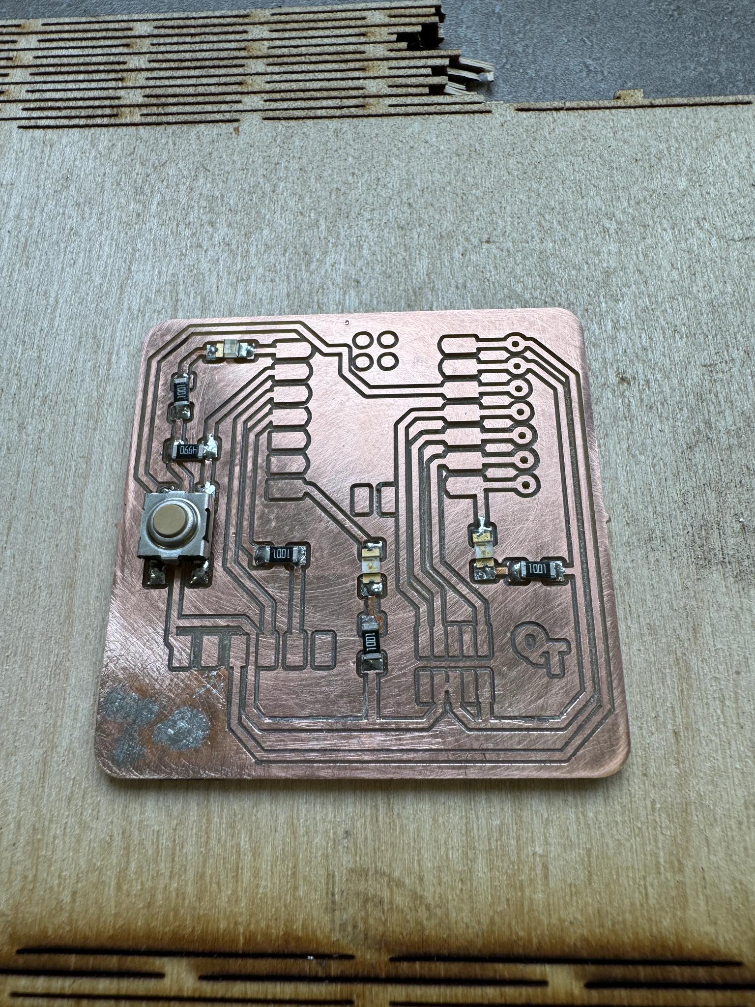
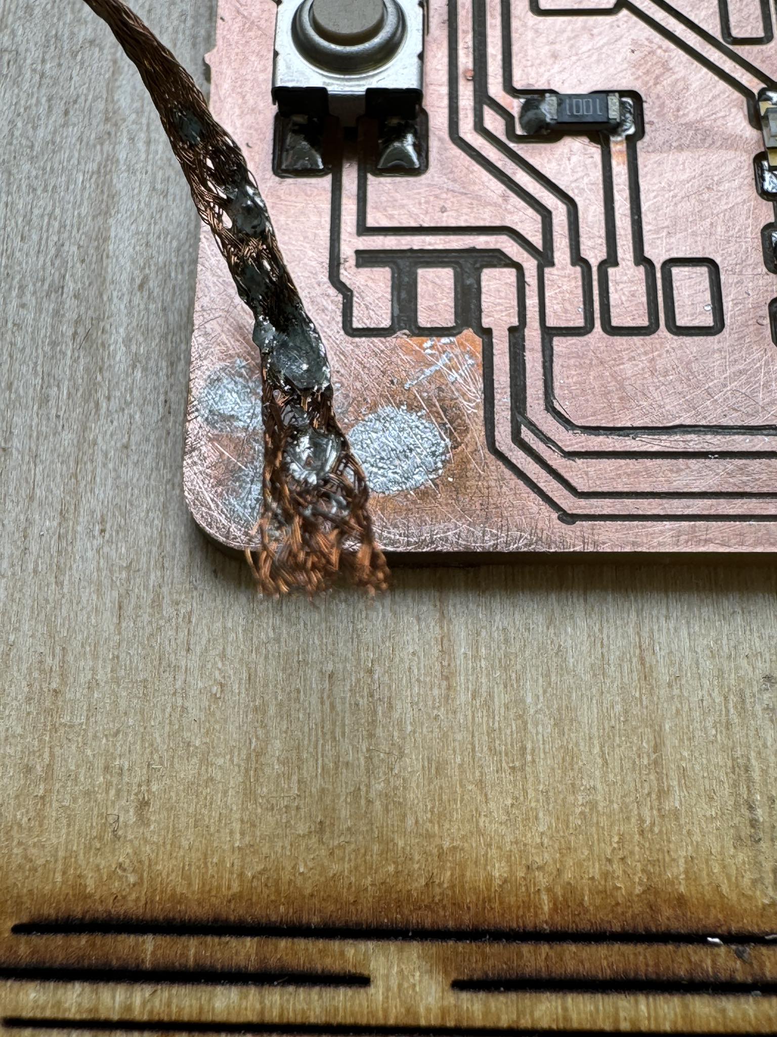
The removed solder on the PCB It was left after trying out the soldering wick?. I was just trying out the wick.
Isolated the microchip with tape. Not to conduct with circuit under it.
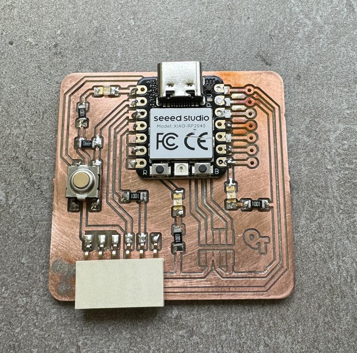
I tried to make solder not overheated to not lose the shine.
Code
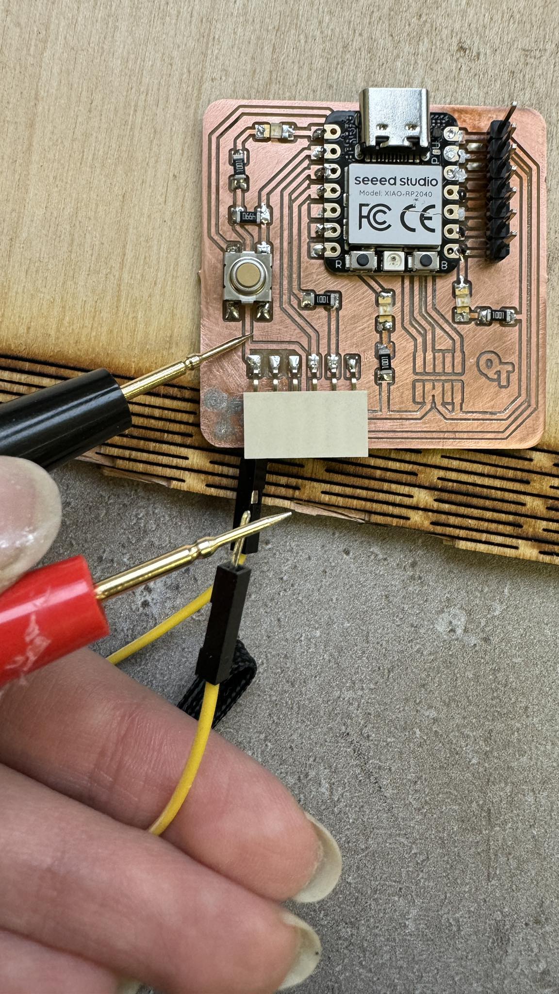
I installed Arduino program. Plugged my circuit into one of the ports on my computer and it started lighting diods. Followed steps for installing library and setting the program here.
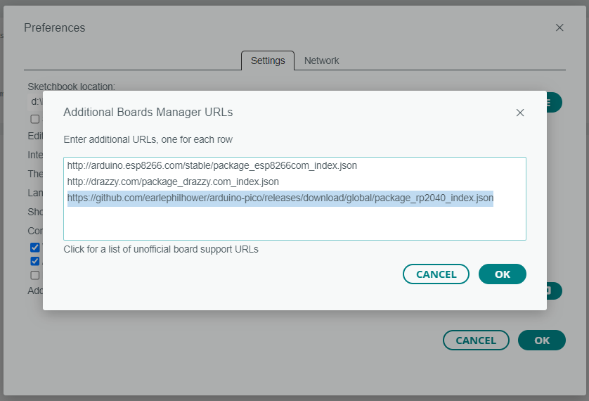
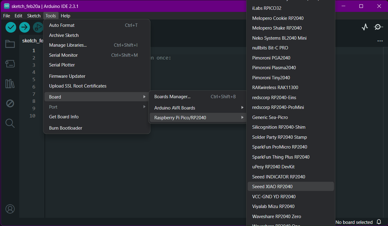
Adding Seeed XIAO RP2040 package to Arduino IDE.
File > Preferences > additional boards manager. Paste following URL.
https://github.com/earlephilhower/arduino-pico/releases/download/global/package_rp2040_index.json
Installed raspberry pi library from Arduino, selected the board and imported library.
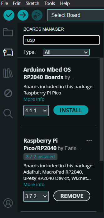
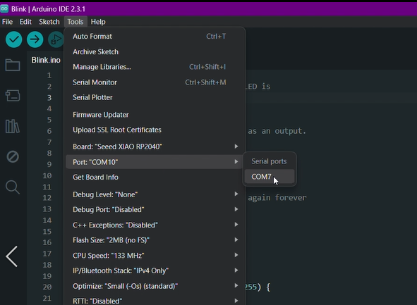
And select port which is plugged in Tools > Port > *
I tried to set blink to the outputs 26 and 0 which were diods connected to the microcontroller.
// the setup function runs once when you press reset or power the board
void setup() {
  // initialize digital pin LED_BUILTIN as an output.
  pinMode(26, OUTPUT);
  pinMode(0, OUTPUT);
}

// the loop function runs over and over again forever
void loop() {
  digitalWrite(26, HIGH);
  digitalWrite(0, HIGH);  // turn the LED on (HIGH is the voltage level)
  delay(400);                      // wait for 0.4 second
  digitalWrite(26, LOW);
    digitalWrite(0, LOW);  // turn the LED off by making the voltage LOW
  delay(400);                      // wait for 0.4 second
}
Group assignment
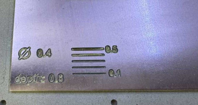
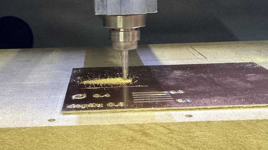
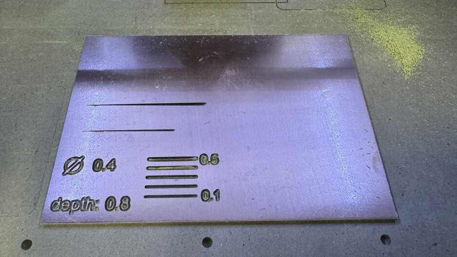
For group assignment we were testing a V-bit mill. To know what are it’s diameters at each depth and to know how to set up the parameters for different thickness. So we started with a simple test drawn in Inkscape. We set up the mill and started engraving these lines.
We set here as an fictive tool diameter as a 0.4 because we didn’t know what it will be at each depth. and started with depth 0.8 to engrave few lines with thicknesses from .1 to .5 mm.
This test could take a lot of time of engraving and so we decided to make a single line which’s going deeper by distance, and then to measure it. For that we needed the mill to spin and follow one axes by encrasing the depth.
Here’s an interesting experience we had thanks to Ashot’s performance of generating a g-code by hand.
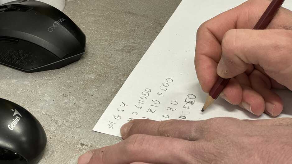
%
G17
G21
G40
G49
G54
G80
G90
G94
S11000
G00Z2.0000
M03
G00Z2.0000
G00X0.0000Y0.0000Z2.0000
G01 Z0 F100
G01 X40 Z-1.6
Z50
M05
M30
%
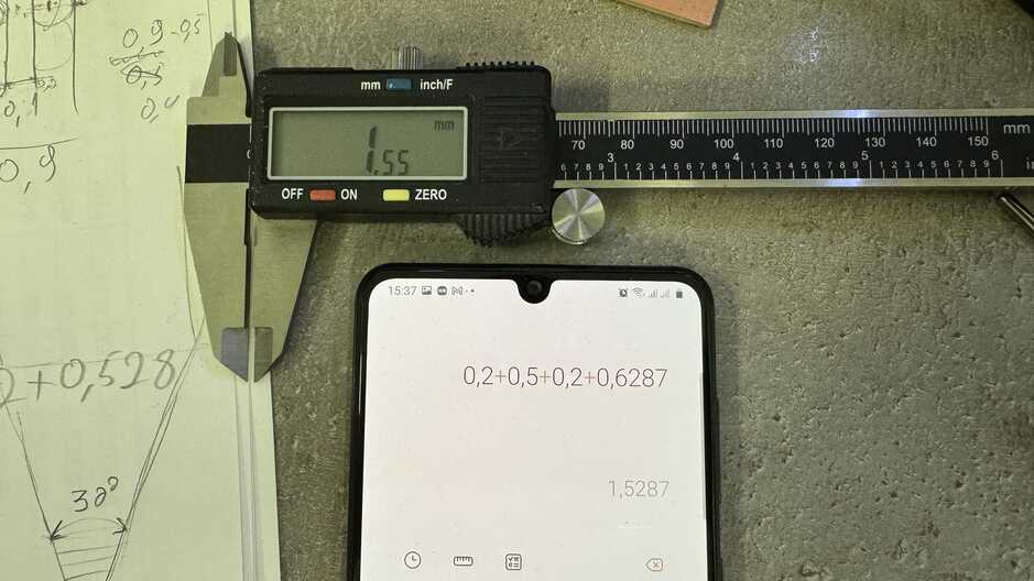
Here are test results. While it was working we were drawing V-bit mill’s shape with real sizes and tried to solve it mathematically.
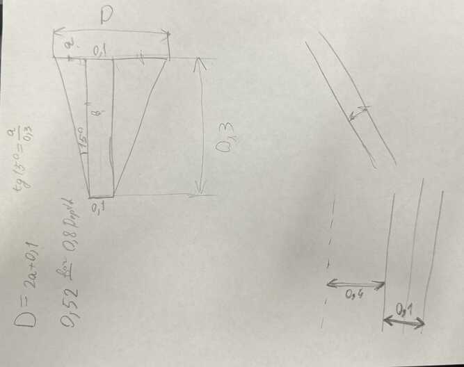
Also as we didn’t know the tip diameter of the V-bit mill, we pretended it 0.2mm. Areg got a formula for calculating the needed parameters.
And while we were testing and measuring all, together with Areg we made a drawing in Solidworks, which’s measuring automatically each depth.
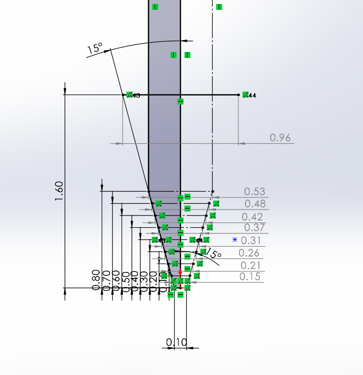
As we didn’t know the tip diameter here we set 0.1mm, but it also has ability to change other parameters if we set 0.2mm. So we couldn’t get perfect results because we have some suspicious parameters as a tip diameter and machine’s vibrations that can give incorrections in measurement but theoretically for 30 degree angled mill, we have found a way to know the depth and thickness with using this parametric drawing in Solidworks. .sldprt file.
After experiment we have an parametric drawing to calculate depth for needed diameter. So before seting milling depth we can set a diameter in a drawing and we will get a mill depth for setting in parameters in g-code.
Conclusion
This week was very interesting. I liked soldering. The only problem this week was that we’re completely new to electronics and we don’t understand what we’re making and what components are on it and actually for what it is. We’ve learned the process of milling the boards and in our group assignment experiment we tested out V-bit mill, which gives opportunity to mill out traces with various thicknesses. We made a drawing which can help to calculate the depth parameter with using thickness.